If you have any relevant data sheets, class handouts or any other information that we
do not have here,
please consider scanning them and emailing the scans to us.
Or loaning them to us and letting us scan them.
Larsen Electronics was founded in 1965 by Jim Larsen K7GE (I've forgotten his original W7 callsign, anybody remember it?).
Leland J. "Jim" Larsen was born in 1919 and got his amateur radio license in 1932. He passed at age 81 in February of 2000
after 68 years in ham radio and 34 years in business.
In 1999 the operation was purchased by Radiall and became Radiall / Larsen Antenna Technologies.
In 2006 Larsen became a Pulse brand when it was acquired by Pulse, a Technitrol Company.
The web site is still at http://www.larsenantennas.com.
Phelps Dodge (also known as PD) was bought by Celwave (year?), which was bought by Radio
Frequency Systems (aka RFS) (year?) whose web site is at
http://www.rfsworld.com.
If you are looking for other web pages containing information on a specific antenna - for
example some repeater group whose web page mentions a Phelps Dodge PD-458 in passing - you
may have to check under all three company names.
For example, under Google, you would type (less the square brackets): [ "PhelpsDodge"
OR "Phelps Dodge" OR Celwave OR "Radio Frequency Systems" OR "RFS" 458 ]. Note that the OR parameter in
a Google search must be in ALL CAPS.
Martin F. Jue K5FLU founded Envision MFJ Enterprises in 1972. MFJ bought Hy-Gain in May of 1999.
Then they purchased Cushcraft in August of the same year. MFJ also owns the Ameritron, Mirage, Vectronics
and MDS-HAM names. Many of their power suppleies were OEM'd from
Zurich Electric, for example the MFJ-4035MV
was a relabled DPS-3012M.
They left the Hy-Gain products at
https://mfjenterprises.com/collections/hy-gain.
Likewise the CushCraft products are at
https://mfjenterprises.com/collections/cushcraft.
Antenna Specialists Co. was founded in Cleveland OH. (year?) and they were still there in August of 1974. They were sold to PCTel (year?) - and their corporate web site was at www.antenna.com which now links to https://www.pctel.com/products/antenna-products/.
The current owners seem to be http://www.pctel.com, and the
product web site is here.
I was told recently that PCTel also bought both Maxrad, Bluewave and Antenex (but I don't know the dates).
Decibel Products Inc. (also known as DP and not as PD) used to be at 3184 Quebec Street in Dallas TX 75247, then at
8635 N Stemmons Freeway in Dallas, TX at (214) 631-0310 and (800) 676-5342. Their web site
was at www.decibelproducts.com. They were acquired in July 1992, by the Allen Group Inc. of Cleveland, Ohio, but the new owners didn't want everything. The leftovers (including duplexers) are now
sold by a new company called dbSpectra, located in Lewisville, Texas... their web site is at http://www.dbspectra.com (will open in a new window).
From their web site: "...in December of 2004, dbSpectra signed a licensing agreement with Andrew Corporation to manufacture
and sell the legacy Decibel Products site management equipment such as filters, duplexers, combiners, tower top amplifiers,
RF power sensors (DB888x and 19C336861-xx series) and more. A number of these products had been outsourced and
dbSpectra successfully brought them back and have since hired many of the personnel involved in the design and manufacture
of these excellent products."
DP antennas is still in operation as "Decibel Products, an Allen Telecom Inc. company".
Update May 2023... Going to the www.decibelproducts.com web site times out and the (214) 631-0310 phone number
is disconnected.
But db Spectra has a "Contact Us" link on their home page and there are working phone numbers and email addresses.
In March of 2006 the Laird Group of England (AKA LairdTech) purchased Antenex for about
$20.5 million, and then in Febuary of 2007 bought Cushcraft for about $90 million.
And about a month later Andrew purchased the English manufacturer Precision Antennas for
about $36 million.
In December of 2007 Andrew was bought by CommScope for US$2.6 Billion.
Here's the current Commscope home page.
They seem to have integrated the Andrew products into their own offerings.
In many cases you will find that manufacturer's web sites have theoretical information that
is applicable to all, i.e. the theory articles on Manufacturer "X" products applies to
Manufacturer "Y" and to "Z". Sometimes researching other manufacturer's web sites can save you
a lot of money. For example, Manufacturer "X" claims that a crystal filter will solve your
desense problem. Then you go to the "Y" web site and there you discover that, yes, a crystal
filter can be used in the receiver feedline to notch out a local signal, or to pass your signal.
What the Manufacturer "X" web site didn't tell you, and the Manufacturer "Y " or "Z" web site
did, is that in your specific case it may not work. Unless you were familiar with crystal
filters you would not know that the insertion loss can be as high as 12-13 dB, which in many
cases makes a crystal filter on a repeater receiver unusable unless you add some amplification.
The signal level budget just isn't there (i.e. while adding the crystal filter would kill the
interfering signal, it also reduced your receiving range to 1/4 of what it was, unless you had
some gain in front of it). So do your homework and learn all you can about the theory behind
the hardware before you spend your money.
An email to repeater-builder had some comments on antenna installation hardware, especially
on a tower:

|
Introductory Information for System Engineering
READ THIS FIRST especially the part about "TYPE" cables. |
|
|
A
Comprehensive Guide to Decibels by Jim Hendershot WA6VQP and the Radio Design Group, Inc. |
|
|
Getting the most from your repeater system
by Kevin Custer W3KKC |
|
|
Motorola R56
Installation Standards and Techniques - 2005 This older revision is here only for reference. |
|
|
Motorola R56
Installation Standards and Techniques - 2017 If anyone hears of a newer version please let us know. |
|
|
Motorola R56 Appendix G,
Mobile Installation Standards and Techniques
This is just one chapter from the above manual (and the only one that mentions mobiles). |
|
|
RF Communications - A Non Technical Approach 1.47 MB PDF
by Decibel Products Corp.
Many years ago Decibel Products (a major RF hardware manufacturer) published a series of
informative pamphlets on systems engineering topics. The earliest seems to be 1964. The
topics included Base Station Antennas, Combiners, Selective Cavities, Duplexers,
RF Transmission Lines and Lightning. Yes, these are old, but the physics doesn't change.
At some point all five pamphlets were combined into a single PDF document titled
"RF Communications - A Non-Technical Approach". DB made it available on their corporate
web site, and the 1996 version is available here as a 1.2 MB local copy
here. This document
should be required reading for anyone wanting to learn about antenna systems. (Thanks
to Duane Hall KA8GVH for the pointer.) |
|
|
TX-RX Tech Aid #77001 767 KB PDF by TX-RX Corp.
Some very useful charts and procedures. Worth printing and adding to your tech notebook. |
|
|
Help!! My repeater seems deaf by Kevin K. Custer W3KKC |
|
|
Repeater Sensitivity De-Sense Testing 325 KB
PDF by Jacques Audet VE2AZX
An excellent writeup that explains the techniques plus shows how to build a high-isolation signal sampler. |
|
|
Receiver
desense testing by Karl Shoemaker AK2O of the Spokane Repeater Group
(Original offsite link at the SRG web
site) |
|
|
Is a 3 dB change in power really worth it? The
answer is "It Depends" by Neil Johnson WBØEMU
If you are in charge of maintaining a repeater system, or building a new one, then this is
worth reading. |
|
|
Some thoughts on Repeater
Receiver-to-Transmitter Isolation by Mike Morris WA6ILQ |
|
|
Guidelines for mounting antennas on
towers 71 KB PDF donated by Skipp
A scan of a guidelines page covering tower-to-antenna distances. |
|
|
ANTPLOT - A Side-Tower Mounted Antenna Pattern Prediction
Program This is a Zip file of both version 5.3 and of version 5.4 of the DOS
program originally provided by Antenna Specialists. It's noted as being "Program No. 3 of the
Antenna Specialists RF TOOLS Series". Also called "tplot" for some reason.
Does anyone have Program #1, #2 and any others? |
|
|
Recommended Coax and Connectors
for the iDEN Enhanced Base Transceiver System 24 KB PDF by Motorola Engineering
They wrote this three page discussion of cable and connector types with regard to combining,
intermodulation, and other RF performace factors. They concluded that LMR-nnn and LMR-nnnn
series cable is specifically NOT recommended in any radio site RF environments, especially
duplex environments (where NNN is any 3-digit number and NNNN is any 4 digit number). While
iDEN is (was?) a 900 MHz system the physics are the same at 28 MHz through 1296 MHz. Well worth
reading. |
|
|
HELIAX Coaxial Cable for Low Intermodulation
Generation 21 KB PDF by Andrew Engineering
They wrote this one page writeup on why foil-braid cable causes intermod. Despite the fact that
you'd expect that conclusion from the makers of Heliax there's a lot less sales pitch and a lot
more engineering presented than you'd think. Worth reading. |
|
|
Where exactly is your repeater? And
are you really sure? Read this before you file any paperwork that has a lattitude and longitude field
and help out your local coordination folks, and prevent an FCC or FAA citation. Donated by Eric
Lemmon WB6FLY (SK) |
|
|
MIL-STD-188-124B "Grounding, Bonding, and
Shielding for Common Long Haul/Tactical Communication Systems including Ground Based
Communications-Electronics Facilities and Equipments" 3.8 MB PDF file
dated 01-Feb-1992
This is the newer military handbook on grounding, and is a
quicker read at about 40 pages, however it says on the second page of the forward that "This
Standard is further implemented by MIL-HDBK-419", listed below. This handbook is
approved for public release and distribution is unlimited. |
|
|
MIL-HDBK-419A "Grounding, Bonding, and Shielding
for Electronic Equipments and Facilities" 9.6 MB PDF file dated 29-Dec-1987
This is the big military handbook on grounding. It is large, in two volumes
totaling about 812 pages. Volume one is 396 pages of theory, volume two is 394 pages of
practice. This download is the complete two volume set in one PDF file, and volume 2 starts
on page 419 of the PDF file. This book covers grounding for safety, lightning, nuclear blast
and most everything else. A very good read and a real eye opener. This handbook is approved
for public release and distribution is unlimited.
At one point (Feb 1999), the hardcopy (including postage) was FREE if you ordered it from:
Commanding Officer
Naval Publication and Forms Center
5801 Taylor Avenue
Philladelphia PA 19120 |
|
|
MIL-STD-464 "Department of Defense Interface Standard
Electromagnetic Environmental Effects Requirements for Systems" 1.2 MB PDF
file dated 18-Mar-1997
"This standard establishes electromagnetic environmental effects
(E3) requirements and verification criteria for airborne, sea, space, and ground
systems, including associated ordnance." This handbook is approved for public release and
distribution is unlimited.
Why, you might ask, is this one on a web page that covers antenna systems? Well,
"electromagnetic environmental effects" includes lightning. And lightning can have
seriously negative effects on antenna systems (and the radios they are connected to). |
|
|
High power amplifiers and duplex radio Tubes vs.
Transistors, by Kevin Custer W3KKC Short version: at high power levels tubes win. |
|
|
Is this connector any good? An article on the
perils of cheap connectors by Jeff DePolo WN3A |
|
|
EMR Corp. Technical Papers Index An
index of downloadable PDF papers on Isolators, Duplexer retuning, Ferrite and Hybrid Combiners,
Multicouplers, Preselectors, Bandpass and Pass-Notch Cavity Resonators. |
|
|
Using Preamps with repeaters... and why sometimes
you wouldn't want to... by Mark Malm NØFAZ and Kevin K. Custer W3KKC |
|
|
The Effects of Trees
on Slant Propagation Paths 1.3 MB PDF by Vogel Hagn
This is an academic paper that will be of special interest to UHF, 900 and 1200 MHz system owners. |
|
|
Best Practices Guide 49 KB
PDF by Motorola Inc.
This is a write up on solving interference problems at 800 MHz and oriented towards Public Safety
communications, but it's worth reading by any repeater owner or builder. There is no document number
on this writeup which is unusual for Motorola. Maybe the document was cropped before it was sent to us? |
|
|
Interference Technical
Appendix 682 KB PDF by Motorola Inc.
This is intended to be an add-on to the "Best Practices Guide" above. Also very worth reading. |
|
|
Calculating Your Radio Horizon by A. Nony Mouse |
|
|
Aiming Link Antennas 1.4 MB PDF file by James Lawrence NA5RC
A method using Google Earth or Google Maps. |
|
|
Radio Mobile Coverage
prediction software by Roger Coudé VE2DBE
Radio Mobile Use by Don Rotolo N2IRZ - A complete guide here at RB®
A support group can be found at
https://groups.io/g/Radio-Mobile-Deluxe
|
|
|
Build a Phasing Harness For Stacking Antennas By Mike Thompson
WB8ERJ (Off-site link - opens in a new browser tab)
Mike needed to make a phasing harness for a two bay antenna, where each antenna was 100 ohms. |
 |
The calculators, especially Dale Bickel's HAAT, Coordinate and Distance calculators are
useful. Scroll down to the Calculators section for them.
|
|
Introductory Information on Cavities, Diplexers,
and Duplexers
READ THIS FIRST
If you're just starting out, I strongly suggest that you read this one and the first dozen or so articles
especially those by John Portune W6NBC, Jacques Audet VE2AZX, Mike Pinfold ZL1BTB and by William F. Lieske. Yes, there is some repeated material between the articles, but if you're new to duplexers,
it won't hurt. When you have multiple people writing on the same topic (or any topic)
some repetition is inevitable.
|
|
Coaxial
Resonators, Applied theory and practice, with photos by Mike Pinfold ZL1BTB (offsite link)
(local copy in case the primary one goes away) |
|
About Duplexers 5.3 MB PDF by Decibel Products
This excellent booklet was written in the 1970s but the physics doesn't change. From the preface:
"This booklet has been written for the many people engaged in two-way radio communications who are
NOT radio engineers. A non-technical presentation of a rather complex subject has been attempted
in an effort to bring about a better understanding of duplexers used in two-way radio systems." |
|
DUPLEXERS - An Introductory Tutorial by
Jack Daniel KD6YVL (SK)
This is a nice writeup that should be titled "Duplexers 101". Well worth reading. |
|
Theory and Testing of Duplexers 1.4 MB PDF by Jacques Audet VE2AZX
This is a large (60 pages) technical writeup that should be titled "Duplexers 102". Again, well worth reading. |
|
Technical duplexer article with good theory and explanations,
plus homebrew construction notes by John Portune W6NBC
Nine chapters discussing just about everything you need to know about cavity duplexers.
A PDF version can be found here as a 1.8 MB file
And here's a YouTube video of a
Zoom presentation that John did for a local club. (Off-site pointer, opens in a new browser tab)
|
|
A homebrew cavity for 29 MHz by Mike Pinfold ZL1BTB (offsite link)
(local copy in case the primary one goes away) |
|
Methods of Tuning Cavity Resonators
According to Application 320 KB PDF by William F. Lieske, Sr., Founder of EMR Corporation
A good basic theory writeup, including the differences in pass and notch cavities and why the cavity diameter is important. |
|
Understanding, Maintaining and
Re-Tuning Antenna Duplexers 145 KB PDF by William F. Lieske, Sr., Founder of EMR Corporation
A good basic theory writeup, including the differences between Band Pass and Band Reject duplexers. |
|
Combating
Spurious Output And Overloading With Cavity Filters 1.2 MB PDF by TX-RX Corp.
A "Seminar Series" writeup that covers the theory behind cavity filters - mandatory reading for those
unfamiliar with them.
Note that cavity filters can’t filter a interfering signal out if it is right on the receiver frequency. No filter can. |
|
How to Tune a Pass Cavity - a video from Telewave (offsite link, opens in a new browser window)
This was found on YouTube in January of 2026.
If the YouTube video ever goes away please notify the page maintainer.
|
|
The RF Filters 'Techbook' 1.9 MB PDF by by dbSpectra Inc.
An excellently written, short (29 pages) writeup. Well worth reading. |
|
Duplexer Theory and Tuning
351 KB PDF by Dave Metz WAØAUQ
An overview of duplexers from an amateur's point of view, with some good hands-on info and some photos
of a good home-brew duplexer. |
 |
A Source of Invar Rod and Sheets
(off-site pointer, opens in a new browser tab)
Several articles on this page involve modifying a cavity or a duplexer. The internal structure of a cavity includes
a threaded tuning rod. These rods are made of a special Invar metal that is temperature stable and hence minimizes
thermal detuning. Invar has been very hard to locate in small lengths and when found is NOT inexpensive. Repeater-Builder
recceived an email pointing out that Invar is available from an industrial supplier named McMaster-Carr as sheets
or rods in lengths as short as 6 inches. The above link goes to that specific page in their on-line catalog. The
rod from McMaster-Carr is NOT threaded but if all you are doing is lengthening a rod you can weld the new (non-threaded) piece into a location where the threads are not needed, perhaps the end next to the cavity plunger.
|
|
Why are there quarter-wave coax cables
between my duplexer's cavities? Gary Schafer K4FMX
This article helps to explain why the fully-cabled duplexer provides more notch depth than the sum
of the separate sections. |
|
Interference
Control Through The Use Of Cavity Filters And Ferrite Isolators 900 KB PDF file by
TX-RX Corp. |
|
Technical
Notes on Duplexer Problems and Remedies 1 MB PDF file by TX-RX Corp. |
|
The Design of High Isolation
Duplexers and A New Antenna for Duplex Systems 772 KB PDF file
An IEEE Transactions publication from March 1965 by W. B. Bryson of Communications Products Company, a
division of Phelps Dodge. |
|
A Guide to Duplexer Specifications over 130
different models, by Paul Kelley N1BUG (contributions to the list are very welcome.) |
|
Tuning
and Adjusting Vari-Notch Duplexers 185 KB PDF file by TX-RX Corp.
A "Seminar Series" writeup that covers the theory behind cavity filters and isolators. |
|
T-Pass
Expandable Cavity Muticoupler System 500 KB PDF file by TX-RX Corp.
A "Seminar Series" writeup that covers the various type of cavity-based multicouplers and the
T-Pass design. |
|
The Hybrid Ring Duplexer A comprehensive
explanation of the Hybrid Ring, by Kevin Custer W3KKC |
|
A Hybrid Ring 6 Meter Duplexer by Jim Poll WB5WPA (offsite link to the wayback
machine) Local PDF copy (1.14 MB)
|
|
Converting a Low Band Sinclair Duplexer from 39 MHz to 52 MHz by Bill Cantrell WD5CVG
Please see the attached PDF on how I converted a Lowband VHF Sinclair duplexer from 39 MHz to 52 MHz.
This article gives you everything you need to know with theory and detailed photographs. Please post on your web site.
This was a lot of fun and I learned a lot from it!
Bill sent this as two parts, they were combined into one 39 page PDF that goes into VERY detailed theory (3.4 MB).
|
|
Refurbishing The DB-4062 Duplexer By Paul Kelly N1BUG
(offsite link) Local PDF copy (471 KB) |
|
Six Meter Heliax Duplexer Design by Jim Poll WB5WPA (offsite link to the wayback
machine) Local PDF copy (1.7 MB)
Here's one implementation of the above design
by Oscar Quintanilla KF6YB (offsite link)
Local PDF copy (478 KB)
Here's
another implementation of the above design by Mike Perryman K5JMP (offsite link)
Local PDF copy (686 KB)
Six Meter Heliax Receive Filter Construction and Testing article
based on the above designs, by Robert Meister WA1MIK and David Malicki N1OFJ.
Note that this is NOT a full duplexer; just the receive half (but it could easily be extended to be a full duplexer).
Yet another implementation of a six meter filter by Tim
Ahrens W5FN
Another six meter Heliax notch filter by Jeff Otterson
N1KDO
Here's yet another implementation of the above design by
John Martin KF8KK (offsite link) Local PDF copy (1.4 MB)
|
|
A 2 Meter Band-Reject Heliax Duplexer by Jim Poll WB5WPA (offsite link to the wayback
machine) Local PDF copy (990 KB) |
|
Some Tests on Duplexer Loops 233 KB PDF file by Jacques Audet VE2AZX
Some interesting observations, including scope traces. |
|
GE Datafile Bulletin 10002-1, A
25-250 MHz Quarter Wave Stub Filter 400 KB PDF file by General Electric
GE's Engineering Staff produced several useful RF Engineering DataFile Bulletins (the ones we have
are available for free download from the GE LBI page at this
web site). This particular one is subtitled:
"Even though General Electric Two Way Radio Transmitters well exceed FCC requirements for spurious
radiation, the 60-80-dB sprious attenuation provided may, in a few situations, be insufficicient to
provent interference. This bulletin describes the construction of a filter, useful for supressing
spurious radiation at one specific frequency." |
|
Someone say 6 meter duplexer? A
comprehensive conversion of a lowband pass cavity to BpBr by Jeff DePolo WN3A. |
|
How do I tune this notch duplexer?
by Kevin Custer W3KKC |
|
Tests of the DCI VHF and UHF 4-pole bandpass
filters by Robert W. Meister WA1MIK
These filters definitely do the job, meeting or exceeding manufacturer's specs. They cover the entire
144-148 and 440-450 MHz bands and have sharp cutoffs. If you need more filtering, they also sell
6, 8, and 10-pole filters with attenuations over 80dB. These handle 200 watts and can be used at
repeater sites.
Update: The company is now called OCI and is at https://www.ocicom.com. (off-site pointer - opens in a new browser tab)
Later Update: OCI company is out of business. If anyone knows of another similar business please let the page maintainer know.
|
|
When
Band-Pass/Band-Reject (Bp/Br) Duplexers Really Aren't Band-Pass by Clinton Turner KA7OEI (off-site link)
Your typical repeater duplexer has both pass and notch functions. This article points out that in many cases the "pass"
isn't good enough - especially when you are at a broadcast site or a commercial site with a number of other tenants.
Your page maintainer was at a site where a GE MASTR II UHF ham repeater was being overloaded by a UHF police dispatch
repeater... the ham system was totally useless for the duration of any activity on the dispatch system, which was totally clean.
Adding a 6-pole OCI filter (UHF) between the ham repeater antenna and the system duplexer completely solved the problem.
|
|
A Homemade Duplexer for 2-Meter Repeaters
820 KB PDF by John Bilodeau, W1GAN (from the July 1972 QST magazine)
Note: In the 50-plus years since this article was written, the spring-contact based BNC has fallen out
of favor. Type N connectors (and to a lesser extent the TNC connector) are much preferred over BNC
connectors as they depend on a silver-to-silver screw compression contact, plus they can handle more
power. You must use double shielded coax in the harness. RG-55 is mentioned in the article,
but I'd use RG-214 or RG-400 and compensate on the inter-cavity lengths. And depending on your
physical mounting situation you may want to use right-angle-connectors. In many cases the same
connector can be used on RG-58 and on RG-400 cable. |
|
Notes and Improvements on the W1GAN 2-meter
duplexer 1.1 MB PDF by Bert Gnaccarini VK3TU
More up-to-date parts and construction techniques for the W1GAN duplexer documented above.
|
|
A Trap Filter Duplexer for 2-Meter
Repeaters 330 KB PDF by Edward P. Tilton W1HDQ (from March 1970 QST)
This article was referenced in the W1GAN duplexer documented above. Worth reading in that it uses tuned
lines and aperatures, not cavities.
|
|
Receiving System
Degradation in FM Repeaters 214 KB PDF by J. A. Murphy K5ZBA (from May 1969 HR)
This article was referenced in the W1GAN duplexer documented above. Describes building an Iso-T and where to place a cavity.
|
|
Speaking of home-made cavities...
114 KB PDF file
This writeup from the UK shows what can be accomplished with aluminum beer barrels. |
|
Speaking of home-made
duplexers... This photo shows what can be accomplished with old fire extinguishers. |
|
Garbage In, No Garbage
Out 2.5 MB PDF file by John E. Portune, W6NBC (from the July 1996 issue of 73 Magazine).
John needed a cavity to protect his 137 MHz weather satellite receiver system from local grunge - and
discovered that a common metal garbage can made a good starting point. |
|
Homebrew Diplexer Design Notes
22 KB PDF file by unknown.
Some hand-written design notes for making a simple 144/440 MHz diplexer. |
|
FM Combining Systems 1.6 MB PDF
file from Shively Labs.
This paper is really about combining systems for FM broadcast and IBOC (HD Radio) but it also has a
lot of good information about pass/reject cavities and circulators in the middle of the document. |
Decibel Products Click here for Decibel Products antennas
Note that Decibel Products ("DB") and Phelps Dodge ("PD") used similar model numbers at times. A DB-506 is very, very different from a PD-506. |
| |
|
Data Sheet on DB's line of power
dividers 268 KB PDF file donated by John Lock KFØM
This writeup covers the K522 and K542 for 144-174 MHz, the K526 and K546 for 406-512 MHz, the K528 and
K548 for 800-960 MHz and the K528M and K548M for 1850-1990 MHz |
| |
|
DB's tube and tower mounting clamp kit
DB-365-OS Early version donated by John Lock KFØM |
| |
|
DB's tube and tower mounting clamp kit
DB-365-OS and ASPR616 165 KB PDF
file (later version) |
| |
|
Catalog pages for early model
DB-4002 band pass cavities 740 KB PDF file
The 4002 cavity covers multiple ranges, the cavity is the same for all of them, the differences are in the loops.
A=118-148 MHz, B=144-174 MHz, C=406-420 MHz, D=450-512 MHz. |
| |
|
Installation
and Tuning Instructions for DB Band Pass Cavity Filters 50 KB PDF file
This information is pretty generic despite the models listed: DB-4001 (148-174 MHz),
DB-4002 (118-512 MHz), DB-4011 (70-88 MHz), DB-4013 (88-118 MHz), DB-4015 (118-148 MHz),
DB-4020 (406-420 MHz), DB-4018 (225-400 MHz), DB-4021 (406-512 MHz), DB-4026 (406-512 MHz),
DB-4028 (806-960 MHz), DB-4042 (30-50 MHz), DB-4170 (138-174 MHz), DB-4171 (450-512 MHz). |
| |
|
Tuning
Instructions for the DB-4022 (UHF) and 4029 (800 MHz) band pass / band reject cavities
32 KB PDF file |
| |
|
DB-4023 UHF duplexer (3 cavity) and 4081 (4 cavity) spec
sheet donated by W. M. Kahl N6KYD |
| |
|
Tuning Instructions for the DB-4030
(four cavity) and 4032 (six cavity) Low Band Duplexers five page 920 KB PDF donated by
W. M. Kahl N6KYD
Tuning Instructions for the
DB-4030 and 4032 4-cavity and 6-cavity Low Band Duplexers 24 KB PDF file (appears
to be a later version of the five page one above)
Converting the DB-4032 Low Band Duplexer
to the 6M Amateur Band 17.5MB Power Point Presentation By “WIRES” KC2FYY
|
| |
|
Installation and
Alignment Instructions for the DB-4036 (mid-band), 4044 and 4046 (high-band) Base Station
Duplexers 48 KB PDF file
A two-page PDF file describing Mid-Band and VHF wide-spaced (3 MHz and 5 MHz) duplexers that are
not of much use to hams, but would be to public safety and disaster services folks. |
| |
|
DB-4042 Resonant Filter
Modifications An offsite link to KB6MIP's Technical Information Page articles. |
| |
|
DB-4048 duplexer specs (high band - 146-174
MHz) 1.22 MB PDF file
DB-4048
duplexer review article from June 1975 QST magazine -
Page 1
Page 2
Scan courtesy of Glenn Little WB4UIV |
| |
|
Modifying/Improving the DB-4048 Notch Cavity Duplexer
by Ralph Hogan W4XE |
| |
|
Installation and Tuning
Instructions for the DB-4055 and 4056 (high band), 4067 and 4068 (406-420 UHF) and 4071
and 4072 (450-470 UHF) duplexers 41 KB PDF file
Here's a photo of the internals
of a 4072 housing. |
| |
|
Installation
and Tuning on Decibel Products 4057 (three cavity) and 4058 (four cavity) high band
duplexers 123 KB PDF file |
| |
|
Catalog sheet on the DB-4060 and 4062
Band Pass/Band Reject duplexers 55 KB PDF file
Installation and Tuning Instructions for the DB-4060
and 4062 Band Pass / Band Reject duplexers 46 KB PDF file
(the DB-4060 has 4 cavities, the 4062 has 6 cavities)
Repair of the DB-4060 and 4062 Band Pass / Band Reject
duplexers 344 KB PDF file
An article by Bernie K5BP detailing notch capacitor replacement for these units, including a source for the original component.
Repair of the DB-4060 and 4062 Band Pass / Band Reject duplexers An offsite web page by N1BUG (opens
in a new browser tab). He writes:
I have a DB-4062, which is the 6 cavity version of the 4060. It was old when I placed it in service
in 1997 but worked OK. Over the years it just slowly deteriorated until it became essentially unusable.
Finally I took the thing apart to investigate, and was able to restore it to excellent function after
15 to 20 hours of work. I created a web page that covered my experience.
Conversion of DB4060 and DB4062 Duplexers for 2 Meter Amateur Radio Use (opens
in a new browser tab)
Offsite link to a web page at duplexerrepair.com on conversion of DB Products (now DBSpectra) "-C" range (154-174 MHz) units to "-B" range (143-156 MHz.
|
| |
|
Specifications and Data on the
DB-4075 and DB-4076 UHF Bandpass Reject duplexers 2.1 MB PDF file
Photo
Wiring Diagram for the DB-4076 UHF
Bandpass Reject duplexer shown in the above photo 28 KB PDF file |
| |
|
Specifications and Data
on the DB-4075W and DB-4076W UHF Bandpass Reject duplexers 423 KB PDF file
Tuning and Installation Information on the
DB-4075W and DB-4076W UHF Bandpass Reject duplexers 91 KB PDF file |
| |
|
Tuning Information on the DB-4090
806-960 MHz Bandpass Reject duplexers 44 KB PDF file |
| |
|
Installation
and Tuning Instructions for the DB-4104 (low band), 4040 (high band) and4075 (UHF) single-cavity notch
filters 25 KB PDF file |
| |
|
Installation and
Tuning Instructions for the 4307, 4308 and 4309 Hybrid Couplers 14 KB PDF file |
| |
|
Installation and
Tuning Instructions for the DB-4318H-2C Single Channel Filter and Isolator 10 KB PDF file
This file describes a 164-168.5 MHz unit but the directions apply to similar units. |
|
|
PD-497 duplexer manual 110
kB PDF file |
|
|
PD-497 duplexer instruction
manual 235 KB PDF file donated by Mike Besemer WM4B |
|
|
PD-506 manual 263 KB PDF file Donated by
Allan Crites WA9ZZU, scanned by Eric Lemmon WB6FLY (SK)
NOTE: You CANNOT tell from the model number if a PD-506 is for 144-174 or for 220-225 MHz! You
have to look at the frequency label!
This is a 4-cavity pass-notch duplexer than is supplied as either a 144-174 or 220-225 MHz version.
At high band it will work from 600 KHz to 7 MHz separation, and at 220 it will work at from 1 to 5
MHz separation. Rejection is specified at 80 dB, and under 2 dB insertion loss. |
|
|
PD-506 duplexer manual 75 KB PDF file
cleaned and PDF'd by WA1MIK |
|
|
PD-522-509 manual 1.1
MB PDF Donated by Bill Hudson W6CBS
The manual says Celwave as they bought Phelps Dodge, and this particular manual was printed after
the purchase.
Does anyone have the factory spec sheet or catalog sheet, the tuning instructions or can supply a
couple of photos? |
|
|
PD-526-509 manual 492
kB PDF file courtesy of Joe Szczech K1IKE
UHF pass/reject duplexer.
Photo 1
Photo 2
Eric Lemmon WB6FLY wrote: This is a 6 Cavity UHF Repeater and Base Station Duplexer that is an
outstanding performer.
Specs:
Frequency Coverage = 435 to 470 MHz.
Minimum Frequency Spacing = 3 MHz.
Minimum TX to RX Isolation = 100 dB
Maximum Insertion Loss = 1.0 dB
TX Bandwidth = 0.025 MHz.
RX Bandwidth = 0.025 MHz.
Maximum Power Input = 250 watts
Connectors = "N" Female
Maximum VSWR (50 ohms) = 1.3:1
This duplexer is also sold by Motorola as part number 0185417U05, which has a current (mid 2009)
dealer price of $1,173. It is made for Motorola by RFS/Celwave, which sells the same unit as
PD526-4-2. It is the X182AD Option for Quantar, Quantro, and MTR2000 stations. I have an identical
unit in service on a 100 watt UHF MTR2000 repeater, and it is an excellent performer. Prior to
installation, I verified that its isolation was better than the 120 dB specified- a very good
figure. |
|
|
PD-638-509-6 manual 263 KB PDF file donated
by Allan Crites WA9ZZU, scanned by Eric Lemmon WB6FLY (SK)
This is a 6-cavity pass-notch mobile duplexer that is available as a 150-162, 162-174, 220-225,
or 471-512 MHz unit.
- 150-162 or 162-174 MHz: 150 watts, 75dB rejection, 1.2 dB insertion loss at 2 MHz spacing.
At 5 MHz the insertion loss drops to 0.7 dB.
- 220-225 MHz: 100 watts, 75dB rejection, 2 dB insertion loss at 1.6 MHz spacing.
- 470-512 MHz: 75 watts, 75dB rejection, 1.7 dB insertion loss at 3 MHz spacing. |
|
|
PD-5042-1 VHF Duplexer data from Motorola
960 KB PDF file scanned by Eric Lemmon WB6FLY (SK)
Motorola relabels the Celwave model PD5042-1-50 duplexers and includes them as factory option with
VHF Quantar or MTR2000 stations. Their part numbers are 0185417U01 for the 132-146 MHz range,
0185417U02 covers 144-160 MHz, and 0185417U03 covers 158-174 MHz. |
|
|
PD-5042-1 VHF Duplexer tuning info from RFS/Celwave
372 KB PDF file
Similar to the above file. |
|
|
PD-7540, PD-7560, PD-7640, PD-7660
duplexer manual 109 KB file
This unit was also marketed as the "MiniPlexer".
This is a UHF flat-pack mobile notch-only duplexer that is limited to 40 watts and comes in two
ranges: 406-435 and 435-470 MHz and in 4 can or 6-can versions (7n40=4-can, 7n60=6-can). The 4-can
version provides 50 dB rejection and 1 dB insertion loss at 5 MHz spacing, and the 6-can
version provides 75 dB and 1.3 dB. Like any notch-only duplexer, any frequency outside
the notches rides right through.
PD-7540, PD-7560, PD-7640, PD-7660 duplexer
manual 518 KB PDF file
This is a later verion of the same manual, with enough new information to be worth having both
versions available. Donated by Allan Crites WA9ZZU, scanned by Eric Lemmon WB6FLY. |
|
|
P-Series Duplexer Specifications Sheet 418 KB PDF file
by Sinclair Corporation
Covers the P-1C01-G, P-1C02G, P-201G, P202G, P203G, P-301G, P-302G, P-303G models. |
|
|
Q202G Series Duplexer Specifications Sheet 233 KB PDF file by Sinclair Corporation
The Q202GC-2 is the “high split” model, covering 148-174 MHz.
The Q202GC-1 is the “low split” model, covering 132-150 MHz. Conversion from one to teh other requires a replacement harnessand re-adjusting the coupling on each cavity. |
|
|
Sinclair Q202-G cable harness
drawing 88 KB PDF file courtesy of Eric Lemmon WB6FLY (SK)
Eric wrote in an email: A while back I set up a Q-202G duplexer for a local radio club. The duplexer
was originally made for and used on a commercial pair in the 152-157 MHz band, and no matter how much
work was spent on tuning the duplexer it would not perform. I had the club purchase a new low-split
harness from Sinclair. When it arrived, I took careful measurements of both the new and the old
harness, and the results are here. If the harness on your duplexer is the high-split version, with
about 12 inches between tee centers, you will never be able to achieve optimum peformance on 2m,
especially in the 145 repeater range. Some people "stretch" the cables by adding 90 degree elbow
adapters to the ends as a test, but while that works you will eventually end up buying or making a
new harness. The factory-made harness uses Delta brand crimped connectors, and was priced in the
area of $250.
Eric continued with "If I were to do this again, I would consider fabricating the harness myself,
with genuine Delta brand connectors and tees, which can be purchased for a total of around $120".
If you do, don't forget to use real mil-spec RG-214 or RG-393 coax with the silver plating (look up
"duplex noise" and "LMR-400" elsewhere at this web site). |
|
|
Tuning instructions for "P" and "Q" series cavity duplexers, and
FP, FR, FQ series cavities 417 KB PDF file by Sinclair Corporation |
|
|
Tuning instructions for the Q-202G, Q-208G, Q-218G,
2B02G, Q-2B02G, Q-2B17G series cavity duplexers 1.06 MB PDF file by Sinclair Corporation |
|
|
Specifications for the Q-201G,
Q-207G, Q202G, Q208G, Q301G, Q302G, Q321G, Q203D, Q502D, Q322D, Q501D series base station
duplexers 710 KB PDF file courtesy of Wayne Paterson KBØSL |
|
|
Tuning instructions for the Q-501D,
Q502D, Q503D series duplexers 720 KB PDF file courtesy of Wayne Paterson KBØSL |
|
|
Catalog sheet and Specifications for the 6 cavity
Res-Lock Q-Circuit VHF Duplexer 355 KB PDF file |
|
|
Tuning instructions for the Q-Series, ResLok
4 - Q‑circuit Duplexers 1.3 MB PDF file
Written on the front is "Sincl Q2330E" |
|
|
Installation and Tuning instructions for the Q‑Circuit
Res-Lock Duplexers 217 KB PDF file
This manual covers the Q-1220E (66‑88 MHz), Q-2220E (132‑174 MHz),
Q-2222E (148‑174 MHz), Q-3220E (406‑512 MHz) and Q-4220E (806‑960 MHz)
duplexers.
Photos of a new coupling loop for a 2220E:
Photo 1
Photo 2
Photo 3
Photo 4 |
|
|
How to Modify a Sinclair Q2220E 132-174 MHz Duplexer to 220 MHz by
David Cameron - VE7LTD (off-site pointer)
This particular modification worked well for David and produced a 220MHz duplexer that exceeds the specs for a Sinclair made Q2221E. |
|
|
Duplexer Tuning Instructions for the R101G to R116G and
R-1C01-G, R-1C02G, R-1A01G models 869 KB PDF file
Note: This manual also covers a large number of other models in the 2H-30, 2H-37, 2H-43, 2H-66,
2H-77, H-30, H-37, H-43, H-66 and H-77 series. The actual list is on the first page. |
|
|
Modification of R101, R104, or R110 for amateur
6 meter operation 976 KB PDF file |
|
|
Another modification of R101-series for
amateur 6 meter operation 781 KB PDF file by D. Edwards W2GBO |
|
|
Hybrid Ring Duplexer Construction
3.2 MB PDF by Gil Boelke W2EUP |
|
|
Hybrid Ring Duplexer Tuning Instructions
By Kevin Custer W3KKC (theory on the W2EUP-designed Sinclair Hybrid Ring Duplexer). |
|
|
Hybrid Ring Duplexer Tuning
Instructions (manual CM-106) 1.1 MB PDF |
|
|
VHF Hybrid Ring Duplexer Spec
Sheet 70 KB PDF file Courtesy of Matt Krick K3MK
For F101, F201, F202, F207 models. |
|
|
MR-354, MR-356 and MR-3332 406-512 MHz
mobile duplexer catalog sheet 191 KB JPG file |
|
|
Mobile duplexer MR-354 Specification Sheet 88 KB
PDF file donated by Ted Maczulat VE7TFM |
|
|
Mobile duplexer MR-356 Specification Sheet 87 KB
PDF file |
|
|
MR series mobile duplexer
tuning 150 KB PDF file
Covers the MR-254 and MR-256 (high band, 4.5-10 MHz separation), MR-354 and MR-356 (UHF, 5-10 MHz
separation), MR-454 and MR-456 (806-952 MHz, up to 45 MHz separation) units. Note that these
duplexers are rated at 50 watts or less. The high band units are built for either 148-160 MHz or
160-174 MHz splits, the UHF are built for either the 406-450 MHz or 440-512 MHz splits,
and the 800/900 units are built for 806-890 MHz and 928-952 MHz splits. |
|
|
"FP", "FR", "FQ" Series Bandpass Filters Product Description
Page 1 34 KB PDF file
Page 2 29 KB PDF file
Donated by Eric Lemmon WB6FLY (SK) |
|
|
"FP" Series Electrical
Specs 27 KB PDF file (undated) donated by Eric Lemmon WB6FLY (SK) |
|
|
"FR" Series Electrical
Specs 31 KB PDF file (undated) donated by Eric Lemmon WB6FLY (SK) |
|
|
"FQ" Series Electrical
Specs 30 KB PDF file (undated) donated by Eric Lemmon WB6FLY (SK) |
|
|
"FP" Series Tuning 61 KB PDF
file donated by Eric Lemmon WB6FLY (SK) |
|
|
"FR"Series Tuning 68 KB PDF
file donated by Eric Lemmon WB6FLY (SK) |
|
|
"FQ"Series Tuning 71 KB PDF
file donated by Eric Lemmon WB6FLY (SK) |
|
|
"FP","FR", "FQ" Series
Parts 23 KB PDF file donated by Eric Lemmon WB6FLY (SK) |
|
|
"FP", "FR", "FQ" Series
Tuning 48 KB PDF file (undated) donated by Eric Lemmon WB6FLY (SK) |
|
|
"FP", "FR", "FQ" Series Tuning 2.64
MB PDF file |
|
|
"P","Q", "R" Series
Description 37 KB PDF file donated by Eric Lemmon WB6FLY (SK) |
|
|
"P" Series Electrical
Specs 40 KB PDF file donated by Eric Lemmon WB6FLY (SK) |
|
|
"Q" Series Electrical
Specs 41 KB PDF file donated by Eric Lemmon WB6FLY (SK) |
|
|
"P" and "Q" Series Preliminary
Tuning 32 KB PDF file donated by Eric Lemmon WB6FLY (SK) |
|
|
"P" and "Q" Series Outlines 42
kB PDF file donated by Eric Lemmon WB6FLY (SK) |
|
|
"P" Series Retuning 58 KB PDF
file donated by Eric Lemmon WB6FLY (SK) |
|
|
"Q" Series Tuning 86 KB PDF
file donated by Eric Lemmon WB6FLY (SK) |
|
|
"P" and "Q" Series Parts 33 KB
PDF file donated by Eric Lemmon WB6FLY (SK) |
|
|
"C" Series Description 53 KB
PDF file donated by Eric Lemmon WB6FLY (SK) |
|
|
"C" Series Systems 79 KB PDF
file donated by Eric Lemmon WB6FLY (SK) |
|
|
"C" Series Electrical
Specs 59 KB PDF file donated by Eric Lemmon WB6FLY (SK) |
|
|
"C" Series Mechanical
Specs 64 KB PDF file donated by Eric Lemmon WB6FLY (SK) |
|
|
"C" Series Curves 49 KB PDF
file donated by Eric Lemmon WB6FLY (SK) |
|
|
"C" Series Typical
Systems 67 KB PDF file donated by Eric Lemmon WB6FLY (SK) |
|
|
"C" Series Tuning 49 KB PDF
file donated by Eric Lemmon WB6FLY (SK) |
|
|
"C" Series Parts 71 KB PDF
file donated by Eric Lemmon WB6FLY (SK) |
| WACOM and Remec |
| WACOM started out as Waco Communications in Waco, Texas. At some point WACOM was
bought by Remec, and in November of 2001 was sold to TX-RX. |
|
Notes on the Wacom WP-641 BpBr Cavity by
Kevin Custer W3KKC |
|
Converting the WP-641 or WP-639 VHF
Duplexers for Amateur Use by Kevin Custer W3KKC |
 |
Clif Holland reports: "I have a set of Wacom WP-639 Cavities made in 27th week of 1996. They were
ordered by our club for 146.90/146.30 MHz. They have crimp-on Amphenol connectors with solder tip
model #182311. The five T-Connectors are Amphenol 49199 M-358. The cables are Coleman Cable 8421F
M17/75 RG-214 Mil C-17. The cables are all the same length: tip to tip 13.225 +/- .01 inches. They
work fine and were cut for our frequency and not converted to the ham bands." |
|
Converting Bp/Br to Bp Duplexer for 220 MHz 890
kB PDF file by Joe Orrico WB6HRO |
|
Field Tuning Instructions for Wacom
6-cavity Bp/Br Duplexers 238 KB PDF file donated by Gary Howell WA9RZY |
|
Field Tuning Instructions for Remec
WP-604, WP-609, WP-612, WP-621, WP-629, WP-639 and WP-641 VHF Duplexers 283 KB PDF file
donated by Eric Lemmon WB6FLY
There's one repeated error in this writeup: In Figure 1 and Figure 2 you need to terminate the
unused port with a good dummy load. |
|
Field Tuning Instructions for Wacom
WP-604, WP-609, WP-612, WP-621, WP-629, WP-639, WP-641 and WP-652 units 973 KB PDF file
donated by Ivan OZ1HYG
This is an earlier version of the above file (it's from Wacom), and the instructions are a little
different. |
|
Field Tuning Instructions for Wacom
WP-678-R2 and WP-665-R2 UHF Duplexers 746 KB PDF file donated by Eric Lemmon WB6FLY (SK) |
|
Spec Sheet for WP-604 (low band, 4-cavity) 371 KB PDF file |
|
Spec Sheet for WP-621 and WP-641 (high band, 4-cavity)
218 KB PDF file |
|
Spec Sheet for WP-622 and WP-642 (high band, 4-cavity)
404 KB PDF file |
|
Spec Sheet for WP-623 and WP-643 (high band, 6-cavity)
178 KB PDF file |
|
Spec Sheet for WP-629 and WP-639 (high band, 4-cavity)
188 KB PDF file |
|
Spec Sheet for WP-637 and WP-638 (high band, 6-cavity)
400 KB PDF file |
|
Spec Sheet for WP-652 and WP-653 (220 MHz, 4-cavity) 248
kB PDF file (March 1997 version)
The September 1985 version (no image yet) has a few differences: the older sheet says 220-300 MHz,
1.0 MHz min. spacing, 350 watts max, gray enamel finish.
The newer sheet says 210-260 MHz, 1.0 MHz min. spacing, 200 watts max, black enamel finish.
The frequency response charts look identical, as do the loss and isolation specs. |
|
Spec Sheet for WP-665 and WP-678 (UHF, 4-cavity)
215 KB PDF file |
|
WP-687-3943 Catalog Sheet (900 MHz, 4-cavity)
145 KB GIF |
|
WP-687-3943 Spec Sheet (900 MHz, 4-cavity)
1.65 MB PDF file |
|
WP-687-3943 Test Sheet (900 MHz, 4-cavity)
1.35 MB PDF file |
|
WP-687-3943 Field Tuning
Instructions (900 MHz, 4-cavity) 409 KB PDF file |
|
WP-4941-7941 Spec Sheet (900 MHz, 2-cavity) 2 MB
PDF file |
|
WP-6943 Spec Sheet (900 MHz, 8-cavity, bandpass) 111
kB PDF file |
|
WP-747L3/447L1 Circuit Filter Spec Sheet (220-222 MHz, 4-cavity,
BpBr) 74 KB PDF file |
|
Introductory Information about Combiners
READ THIS AFTER you read the "Cavity" intro piece and
then the "Isolators and Circulators" intro pieces as they are critical components of a combiner.
Then read this article, then read the first five articles below...
|
|
About Combiners 511 KB PDF
by Decibel Products (1975)
From the preface: "This booklet has been written for the many people engaged in two-way radio
communications who are NOT radio engineers. A non-technical presentation of a rather complex
subject has been attempted in an effort to bring about a better understanding of combiners used
in two-way radio systems." |
|
|
Comprehensive guide to
understanding N-way transmit combiners with lots of theory and examples 3.9 MB PDF by Neil Johnson WBØEMU
|
|
Combiner and Receiver
Multicoupler Design 55 KB PDF by Bird Technologies |
|
Ferrite-Filter Transmitter Combiners 238 KB PDF by EMR Corp.
While the examples in this writeup are 800-900 MHz the technology is the same all the way down to 25 MHz. |
|
Understanding Hybrid-Filter Transmitter Combiners 126 KB PDF By William F. Lieske, Sr. Founder, EMR Corporation
Hybrid combiners are older than ferrite-filter combiners and have a higher insertion loss (minimum of 3dB) but they do have their place. |
|
Tuning
Instructions for the DB-4350 and DB-4360 Low Loss Combiners 8 KB PDF file |
|
Tuning
Procedure for Two-Transmitter Combiners DB-4351, DB-4381, DB-4352, DB-4382, DB-4384 65
kB PDF file
This file describes the tuneup of a unit that is essentially two isolators, two low pass
filters, a hybrid coupler and a dummy load. |
|
Installation and Tuning Instructions
for the ACT27nnJ2 and DBNXTL27nn Transmitter Combiner 85 KB PDF file
5-Channel Models: ACT2705J2, DBNXTL2705
10-Channel Models: ACT2710J2, DBNXTL2710
15-Channel Model: ACT2715J2
20-Channel Model: ACT2720J2
|
|
Tuning Instructions
for the DB-4379 Low Loss Combiner 9 KB PDF file
This file describes a unit for up to eight transmitters. |
|
"Celwave 220 Antenna Systems Offerings" 580 KB PDF file
Back when 220-222 was stolen from the hams to be a new land mobile radio band Celwave put together this
brochure with the tech specs on all of their 220 MHz products and included three sample system diagrams.
The products include the PD220-8, PD220DT, 92.0101, and 93.0024 antennas, the TJD220-5T transmitter
combiner, PD1604B cavity, PD5042-2 duplexer, PD5279 cavity, PD5280-1, PD5280-2 and PD5280-3 duplexers,
PD1602 low-pass filter, PD506-2A duplexer, PD5091-2A dual notch cavity, PD5090-2B/3 bandpass filter
and the PD5090-2A bandpass cavity.
And DON'T do what the System #3 drawing shows... don't give your transmit antenna the preferred position on the tower. ALWAYS favor your receive antenna. |
|
Speaking of home-made cavities...
114 KB PDF file
What does this have to do with Combiners? A combiner has cavities as part of the unit, and this article is a
very well written description of a low cost VHF combiner system that started with beer barrels (and could
have as many as 27 transmitters on one antenna). |
|
Combining a VHF voice repeater and a VHF
digipeater 500 KB PDF file by Eric Grabowski KH6CQ
A detailed writeup on how to share one antenna and feedline across two separate transmitters by adding some
filtering and a combiner. While this article is VHF the same twchniques work on any band... 220, UHF, 1200 and more. |
|
Adding an APRS Digipeater to a VHF
Repeater 82 KB PDF file by Dwayne Kincaid, WD8OYG
Dwayne stacks two duplexers to add a digipeater to a VHF repeater.
This article is referenced in the above Eric Grabowski article. |
|
Introductory Information on Antennas READ THIS FIRST
This section is for Station antennas (Base and Repeater), down towards the bottom of this web page there
are sections on mobile antennas and antenna construction projects. |
|
Radio Antenna Engineering 38.5 MB PDF file by
Edmund A. Laport
This is a 1952 textbook and the original copyright has expired.
(The interesting story behind the PDF file)
At the time, Mr. Laport was the Chief Engineer of RCA International Division. While the book is oriented towards
antennas up to 30 MHz, the Preface is worth reading (4 pages) as theory doesn't depend that much on wavelength.
The Introduction (11 pages) has some math, but it's also very interesting. The original book comes with a large fold-out map as part of one appendix.
(available here as a separate file)
Update July 2024: Courtesy of Rutger de Haan VA6WOF the original PDF has been OCR'd and is now text searchable.
|
|
The W1GHZ Online Microwave Antenna
Book by Paul Wade W1GHZ (ex N1BWT) An excellent text, and worth reading. (offsite
link) |
|
Antenna Design for Omnidirectional
Repeater Coverage 1 MB PDF file by James Ruxlow N9SN
What do you do when you need omni coverage, and you have to side mount the antenna to a triangular
tower that is over fifteen feet on each face? The Western Illinois ARC figured it out. And their
solution works well. |
|
The Effect of Metal Support
Structures on the Performance of VHF and UHF Antennas 2.8 MB PDF file by Pye Telecom
Deals with half-wave dipoles and yagis mounted on various supports. |
| Precipitation
Static and Duplex Radio... The Phenomena and the Cure! Rain and snow
clouds contain more than rain and snow by Kevin Custer
W3KKC. |
|
Help!! I have a crackling
noise in my repeater Why it's there and how to cure it... by
Kevin Custer W3KKC. |
|
Vertical and Horizontal antenna
separation charts Provided by Kevin Custer W3KKC. |
|
Information on a Cycloid Dipole
(also known as circular polarization) antennas by the WA7X crew (offsite link) |
|
Calculating Downtilt 39 KB PDF file by Scala
Division of Kathrein Corp (Technical Bulletin #112) |
|
Calculating Downtilt and Distance by Bryan K. Dorbert
N3ST |
|
Side Mounted Radiation
Patterns 123 KB PDF file by Scala Division of Kathrein Corp
Appears to be a scan of a page from from a catalog. |
|
Side mount antenna patterns
279 KB PDF file
A scan of a page from the "Engineering Notes" section in an old Decibel Products catalog |
|
Omni-Directional Gain Vertical Collinear Construction
Project by Mike Collis WA6SVT
Yes, you too can build a Stationmaster or SuperStationmaster - for any frequency from 2 meters to 1.3 GHz
This writeup originally appeared in the May 1982 issue of 73 magazine, later revised in the
August 1990 issue of 73 magazine. |
 |
A NEC Model of the WA6SVT Omni-Gain Vertical Collinear for VHF and UHF by Owen Duffy VK1OD (off-site pointer, opens in a new browser tab)
(local PDF copy (1.7 mb) in case Owen's web site goes away) |
|
|
Some variations and constructions ideas on the WA6SVT UHF collinear by Kevin Custer W3KKC |
|
|
One ham's experiences with the WA6SVT antenna by Paul Kelly N1BUG |
|
|
Here's the construction article promised in the
above article by Paul Kelly N1BUG |
|
Some Notes On
Stationmaster-Type Antennas by Karl Shoemaker, AK2O of the Spokane Repeater Group (off-site pointer, opens in a new browser tab)
(local PDF copy (1.65 mb) in case that web site goes away) |
|
Retuning a Stationmaster
type antenna by Jim Barbour WD8CHL |
|
|
Build A 9 dB, 70cm, Collinear
Antenna From Coax by Michael Martell N1HFX (was an offsite link, now a local copy)
Yes, you can build a decent home base station antenna from RG-58 coax. |
|
|
Stationmaster-type antennas can be over 20 feet tall, and that can result is a lot of top-flexing that can crack the internal connections, and ice loading and winter storms can make the flexing worse. DB Products made a "
Top Sway Brace" that greatly increases the life of these antennas.
The same brace is available from Kevin KAØJQO at Commander Technologies.
Personally, before I clamped the brace to the antenna tube I'd protect the gelcoat on the fiberglass with a piece of radiator hose or heater hose. |
|
|
Fiberglass Antenna Painting
Procedure 318 KB PDF file by Celwave Corp. provided by Mike Dees N3EZD. See the next article as well. |
|
Some Notes on Fiberglass Antenna Painting Comments from several folks that accompany the above article. |
|
Experimenting with 6 meter Ground-plane Antennas by John Haserick W1GPO |
|
Raising the frequency of a Kreco CO-41A Low-Band Antenna 665 KB PDF file by Steve Dold W6KCS
While this only lets you raise the frequency about 3 MHz, it's better than nothing. |
|
Antenna Clamp Selection Guide
by Sinclair Laboratories 1.7 MB PDF file |
| Decibel Products / RFS |
 |
IMPORTANT! A letter suffix indicates the range that an antenna is built for a specific frequency
range: 138-150 MHz, 150-160 MHz, 155-165 MHz, or 164-174 MHz but that the
actual end frequencies and the assigned letter is NOT consistent across the product line.
For example, on one product (i.e. one model number) an "A" model might be 150-159 MHz, while on
another product an "A" model might be 150-155 MHz (4 MHz narrower). While in many cases
an "A" range is the one that starts at 150 MHz, it can vary with EACH antenna model number: one antenna
might have "A" be the 138-150 MHz range, and another might have "E" be the 138-150 MHz
range. Be very careful that you check your range letter definition before you spend your money (on new
or used antennas)! |
|
A list of Decibel Products antenna models and data
68 KB PDF file Compiled by Bob WA1MIK in August 2012. |
|
Data sheet on the DB-201 ground plane omni antenna:
This is the so-called "bent-over" ground plane that is rated at unity gain and 500 watts.
This is a one-page version from the Allen Telecom
vintage 733 KB PDF file
It was available for any frequency from 30 MHz to 512 MHz. The ranges are: A=30-33 MHz, B=33-37
MHz, C=37-42 MHz, D=42-50 MHz, E=66-88 MHz, F=100-144 MHz, G=144-150 MHz, H=150-174 MHz, J=225-406
MHz, JJ=220-222 MHz, K=406-512 MHz, L=Uncut 30-50 MHz, M=Uncut 144-174 MHz, N=Uncut 406-512 MHz.
This is a two-page version from Decibel Products
166 KB PDF file dated 1995.
|
|
Cutting chart for the DB-201 Page 1 159 KB
Page 2 111 KB Allen Telecom version courtesy
of Russ Stafford W3CH
The same info in a four page PDF, better presented, from
Decibel Products 855 KB PDF file |
|
A cutting chart for the DB-201 / PD-128 folded
monopole antenna 60 KB XLS file |
|
The DB-205 coaxial antenna catalog sheet 260
kB PDF file |
|
The complete cutting chart for the DB-205 coaxial
antenna 185 KB PDF file donated by Jim K1VTY, cleaned up and reduced in size by Bob WA1MIK.
The charts cover 33-174 MHz. |
|
A poor scan of the data sheet on the DB-212 side mount omni antenna (33-88 MHz)
Page 1 260 KB Page 2
203 KB Drawing of the diagram on Page 2 34 KB
Here's the Andrew version of the same catalog
sheet 108 KB PDF file (a much better scan) courtesy of Allen Wilde N1IOE
and here's the DB-212
tower mounting instructions 141 KB PDF file also courtesy of Allen Wilde N1IOE |
| |
You can move a low band DB-212 to 6m by basically freeing up the trombone section of the
antenna, adjusting the postion, then locking it down again. Just measure the current length of
the dipole and then multiply this length by (current-freq divided by the new-freq). So if the
current length is 184 inches and the current freq is 46 MHz and your destination frequency is
52.5 MHz the new length (in inches) is therefore 184*(46/52.5). To change the length you will
need to remove the pop-rivet and a little dimple that the production line uses to hold the
trombone in place until the rivet is installed. Sometimes the VSWR depends on the tower face.
If you want to super tune the antenna set the antenna up on a tower leg several feet off the
ground, preferrably a little over a 1/2 wave if you can do it. Then adjust the trombone to the
length you calculated and apply a little RF power and check the reflected power. Then get a long
stick and start moving the trombone slowly while watching the reflected power. When you get the
best possible VSWR, stop and redo the rivets. Personally I'd add a bead of non-acidic silicone
bathub sealer to water-seal the joint. |
|
Detailed measured diagram of the low-band four-element
DB-212 wiring harness Courtesy Bill Cotter N4LG. |
|
WA1ZYX's web page about modifying the
DB-212 elements for 6 meters (offsite link)
(local copy) |
|
Andrew DB-222 Installation Instructions for
DB-222 and DB-222E two-bay antennas 82 KB PDF file. |
|
Detailed harness lengths for various DB-222 multi-bay
antennas Courtesy of Paul Dumdie W9DWP. |
|
Andrew DB-222-JJ detailed measurements and other useful
information 561 KB PDF file Provided by Skipp. |
|
DB-224 catalog data (PDF files): Decibel DB-224
Data Sheet 154 KB PDF file Andrew
DB-224 Data Sheet 140 KB PDF file
DB-224 Instruction Sheet 158 KB PDF file
Here's the instruction sheet that comes in the box with the DB-224
Page 1 964 KB
Page 2 1,032 KB
Page 3 819 KB Courtesy John Lock KFØM.
The DB-224 is the standard antenna that all other 2m/ high band repeater antennas are
measured against. The nearest substitute for the DB-224 is the RFS Celewave 340. Both cost a
little more than a fiberglass antenna but will easily last 20-30 years, and don't have
the cracked joint duplex noise problem, nor will you have
a pile of fiberglass toothpicks on the ground after a nearby lightning strike. How many Hustler,
Comet or Diamond antennas will you go through in 20-30 years?
(and how many trips up and down the 4x4 road and then up and down the tower?)
The DB-224 is rated at 80 MPH winds, but that's wishful thinking unless you side mount it with
clamps on BOTH the top AND the bottom. Frankly, chosing to mount your antenna on the tower top
only to get a few extra feet isn't worth a bent or broken metal support tube, and if your antenna is side
mounted (even if the tip is only 6 feet down from the tower top) the tower itself (or someone else's
antenna) can be the lightning rod and take the hit.
Note that all "DB-224"s are not the same; they may all be tower-mounted exposed dipole arrays
with 6 to 8 dB of gain (depending on the pattern), it's the suffix letter(s) that is of utmost
importance:
- the DB-224-A model is 150-160 MHz circular pattern,
- the DB-224-B model is 155-165 MHz circular pattern,
- the DB-224-C model is 164-174 MHz circular pattern,
- the DB-224-E model is 138-150 MHz circular pattern (but try and find one second hand),
- the DB-224-FAA model is 127-141 MHz circular pattern (it can be shortened to 2m),
- the DB-224-F model is 160-170 MHz circular pattern,
- the DB-224-J model is 276-285 MHz circular pattern,
- and the DB-224-JJ model is 220-225 MHz circular pattern,
- the DB-224E-A model is 150-160 MHz offset pattern,
- the DB-224E-B model is 155-165 MHz offset pattern,
- the DB-224E-C model is 164-174 MHz offset pattern,
- the DB-224E-E model is 138-150 MHz offset pattern (again, try and find one second hand),
- and the DB-224E-JJ model is 220-225 MHz offset pattern,
- The DB-224 series can be ordered as a single or dual antenna. Just modify the model number by
adding an "S" in the right spot - a DB-224-JJ single antenna becomes a DB-224S-JJ as a dual antenna
(with 1/2 the gain). It amounts to separating the elements into two independent antennas on the same mast.
Each antenna has a separate feedline terminated at the bottom of the mast. A DB-224ES-A or DB-224ES-JJ
is a dual feedline antenna with the offset pattern.
- And I've been told that at one point (maybe still can) you could order a new DB-224 less the
tubular mast, and supply your own. Supposedly one group built up a "single antenna" as defined by
their site agreement that was made up of a UHF stationmaster-type fiberglass stick on the top of
an extended length tube, a VHF DB-224 in the middle, and a end-mount UHF beam clamped a couple of
feet below the bottom element and a few inches above the lower end of the tube.
|
|
A detailed drawing of the DB-224-A and DB-224-E
106 KB PDF file donated by Skipp
Note that the element length measurements are shown for both the "A" (150-160 MHz) range
and the "E" (138-150 MHz) range. There is enough information here that anyone with some
experience bending aluminum tubing can build one for themselves. Or if you are going to build your
own and want extra strength you could use aluminum rod. |
|
A detailed drawing of the DB-224-JJ
14 KB PDF file
Roger White W5RDW measured a DB-224-JJ; the drawing is by Skipp. |
|
Another detailed drawing of the DB-224-E
61 KB PDF file Donated by Doug Zastrow WBØUPJ
Note that the element length measurements shown in the diagram are for 138-150 MHz frequencies. |
|
More DB-224 wiring harness drawings 56 KB
PDF file. Complete with calculations. |
|
Details of the DB-224-E wiring
harness 1.7 MB PDF file
Additional detailed drawings of various parts of the wiring harness can be found below (all are
PDF files):
|
|
Conversion calculations for moving your DB-224 to
a different band split. 90 KB PDF file
All of the magic calculations plus coax types necessary to redo your DB-224's wiring harness and set
the element length and spacing. |
|
Converting a DB-224 or DB-222 to the 2M ham band
Original author KC4WC |
|
The DB-225 is a single element, 5 dB gain dipole station antenna that provides a "semi-circular
radiation pattern" (their term, not mine). It uses a director element that is built into the dipole
assembly to shape the pattern - if you end up with a used one and it is missing the director there's
no telling what the final pattern will look like. The antenna can be ordered for any frequency
from 30 MHz to 174 MHz. The catalog claims that you can stack the antennas and get 8 dB gain
with 2 antennas and 11 dB gain with 4 antennas. The data sheet is very specific that it must
be mounted "2 to 3 feet below the top of the tower or tube support. At the same time it must be
clear of all guy wires or metal objects for 2 to 3 feet." |
|
From an email from Ken Decker WA6OSB: Here's the paperwork that was shipped with a DB-225. I
thought it might be useful in the R-B Antenna section.
DB-225 data 303 KB PDF file |
|
The DB-228 is essentially two DB-224s on one 41-foot long mast, and can be ordered with a phasing
harness that makes it one antenna - and that makes it the ultimate 2m repeater antenna (10
to 12 dB depending on the pattern). The catalog sheet shows the "normal" mounting has being
a split mount: the top half is above and the bottom half is below the top of a tower (i.e. the
bottom half is side mounted with two clamps at the middle and bottom); however, unless you want to
be the lightning rod the DB-228 can be fully side mounted with the two brackets at top and bottom,
or an optional third bracket can be added in the middle (I certainly would, especially in any area
that has a problem with high winds, antenna icing, or both).
Or if you need extra RX-TX separation: order it with the -S (split kit) option and use it with two
feedlines and a split duplexer as separate DB-224 receiving and transmitting antennas.
Note that on this antenna an A suffix indicates 150-160 MHz, B=155-165 MHz, C=164-174 MHz and
E=138-150 MHz.
DB-228 Data
Sheet 89 KB PDF file DB-228
Instruction Sheet 62 KB PDF file
Here's the instruction sheet that comes in the box with
the DB-228 772 KB PDF Courtesy John Lock KFØM |
|
DB-264 installation instruction sheet
159 KB PDF file Courtesy of Paul Kelly N1BUG
The DB-264 is a 4 element dipole array that is constructed for any 10 MHz segment of 150-285 MHz.
This is the model that has the feed harness hidden inside the support tube. I've seen one of these
on 224 MHz, and it's rugged! |
|
DB-304 4-bay VHF harness data sheets
450 KB PDF file Courtesy of Jim Dempsey, PDF'd by Bob WA1MIK
15 pages of detailed factory manufacturing and assembly information. |
|
DB-314 instruction sheet 114 KB PDF file
The DB-314 is essentially 8 UHF dipoles (a DB-408,6.6 dB gain) and 4 high band dipoles
(half of a DB-304, 3.2 dB) on the same mast, with separate feedlines. If you need a commercial
grade dual-band antenna, this is it. Or if you are limited to one antenna, then order this guy and
use it as separate 2m and 440 antennas with two feedlines, or with a pair of commercial-grade TX-RX
Corp. (or similar) "diplexers" that put both antennas on one feedline. But don't try and use one on
a 147.09 MHz; repeater paired with a second repeater whose input is 441.275 MHz, or
147.36 MHz; and paired with 442.075 MHz; (I shouldn't have to tell you to do the math,
and it doesn't matter what antenna you have in that situation). |
|
The DB-404 UHF dipole array is two pairs of UHF dipoles mounted to a mast.
Photo Here is the factory data:
DB 404 Data Sheet 95 KB PDF file
DB 404 Instruction Sheet 134 KB PDF file
Catalog sheet Page 1 879 KB
Catalog sheet Page 2 568 KB
The frequency range suffix: A = 406-420, B = 450-470, C = 470-488, D = 488-512, and the "E" range
is either 482-494 or 440-450 depending on which catalog you read, be very, very careful when
ordering one of these. Do it by frequency range, not suffix letter. The SWR is specified as
under 1.5 (or less) across the entire range specified in the suffix letter. According to the spec
sheet the standard connector is a male N, but I've seen installations with a PL-259 on the harness,
and it looked like a factory harness. |
|
A detailed drawing of the DB-404-B 30 KB PDF file
Donated by Skipp
Note that the element length measurements shown in the diagram are for 450-470 MHz frequencies. |
|
A detailed drawing of the DB-404-D 28 KB PDF file
Donated by Skipp
Note that the element length measurements shown in the diagram are for 488-512 MHz frequencies. |
|
The DB-408 is essentially two DB-404s stacked on one longer mast (almost 9.5 feet long) and
can be ordered with one or with two feedlines (the "split kit"). Specify Omni or Offset pattern
when ordering, and if top or side mounting when ordering. For side mounting order the DB-5012
mounting kit.
Here is the DB-408 UHF dipole array factory data: DB-408
Data Sheet 92 KB PDF file DB-408
Instruction Sheet 81 KB PDF file
On this antenna the power limit is 250w, the frequency range A = 406-420, B = 450-470, C = 470-488,
D = 488-512.
The "E" range is either 482-494 or 440-450 depending on which catalog you read, be very, very
careful when ordering one of these. Do it by frequency range, not suffix letter. |
|
A detailed drawing of the DB-408-B 29 KB PDF file Donated
by Skipp
Note that the element length measurements shown in the diagram are for 450-470 MHz frequencies. |
|
DB-411 UHF dipole array factory data: (PDF files) DB
411 Data Sheet 75 KB PDF file DB
411 Instruction Sheet 223 KB PDF file
|
|
A detailed drawing of the DB-411-B 25 KB PDF
file Donated by Skipp
Note that the element length measurements shown in the diagram are for 450-470 MHz frequencies. |
|
The DB-420 is essentially two DB-408s stacked on one longer mast and can be ordered with
one or with two feedlines (the "split kit"). Specify Omni or Offset pattern, and if top or side
mounting when ordering. |
|
A drawing of the DB-420-B phasing harness
143 KB PDF file
This is the 450-470 MHz version. Anybody have a drawing (or the measurements) for 440-450 MHz ? |
|
The data sheet on the DB-420 UHF dipole array
117 KB PDF file
The DB-420 is an array of 8 dual dipoles that can be configured as a single 8-element antenna or as
two 4-element antennas on the same mast (conversion requires a different harness).
|
|
The DB-420 UHF dipole array Assembly
and Mounting Instructions 148 KB PDF file |
|
Factory 1-page data sheet on the DB-492, DB-493 and DB-498
806-960 MHz Yagi beam antennas 133 KB PDF file
This is the data sheet on the welded beams that are 6, 8 or 9 dB. The 492 and 493 are light
duty, the 498 is heavy duty. Phasing harnesses for 2 or 4 antennas are available for up to
15 dB of gain. |
|
Factory 2-page data sheet on the DB-844H90E-XY directed
dipole antenna 122 KB PDF file
806-896 MHz and 870-960 MHz antennas with 12-15 dB of gain. |
|
Factory 4-page data sheet on the DB380
pipe mounts 237 KB PDF file
Also for DB5083 downtilt mounts for panel antennas.
See the note above on "pipe" versus "tube". |
|
Factory data sheet on the DB-5004 / DB-5030
Outrigger 387 KB PDF file
This is the data sheet on the fiberglass outrigger that supports the Stationmaster and
SuperStationmaster style fiberglass monopoles. You want to use at least one, in really high
wind/bad weather areas I've seen two on a 21 foot SuperStationmaster). |
| Telewave See the note at the top of the page regarding Telewave and an amateur discount. |
|
|
Click here for the antenna section at the Telewave web site. (off-site pointer, opens in a new browser tab) |
|
|
What's Inside Your Sinclair or Telewave Style Folded Dipole Antennas? 380 KB PDF (Off-site pointer, opens in a new browser tab)
The Sinclair and Telewave are similar designs and the secret is the design and construction - a magic length of 125 ohm coax internal to the dipole element, and a termination at a magic spot on the inside of the dipole element.
This is a local copy of a web page by Burton Lang VE2BMQ. |
|
|
Does anyone have additional data sheets or scans of the box-stuffing literature that
Telewave ships with their antennas? |
|
|
Telewave
Antenna Connection weatherproofing 89 KB PDF file |
|
|
Telewave
138-152 MHz Yagi 189 KB PDF file
3 elements, 5dB, 500w, 38 inches boom length, 42 inches longest element |
|
|
Telewave 415-450 MHz Yagi
166 KB PDF file
7 elements, 10 dB, 500w, 41 inches boom length, 13 inches longest element |
|
|
Telewave Discone
Antenna 75 MHz to 3 GHz 75 KB PDF file
(500w, SWR is between 3:1 and 1.5:1 below 95 MHz, 110 degree vertical beamwidth, 53 inches
tall, 26 inches diameter, shipping weight is 102 pounds) |
|
|
Telewave Discone
Antenna 118 MHz to 3 GHz 90 KB PDF file
(500w, SWR is less than 1.5:1, 110 degree vertical beamwidth, 36 inches tall, 25.5 inches
diameter, shipping weight is 10 pounds) |
|
|
Telewave Discone
Antenna 400 MHz to 3 GHz 65 KB PDF file
(500w, SWR is less than 1.7:1, 110 degree vertical beamwidth, 48 inches tall, 8 inches
diameter, shipping weight is 41 pounds) |
|
|
Telewave
Dipole Mounting 32 KB PDF file |
|
|
Telewave
Dipole Pattern Configuration 30-300 MHz 171 KB PDF file |
|
|
Telewave
Dipole Pattern Configuration 300-1000 MHz 179 KB PDF file |
|
|
Telewave 45-54 MHz dipole
antenna 127 KB PDF file
500 watts, 1 to 2.5 dB, occupies 9 feet of tower space |
|
|
Telewave 138-174 MHz dipole
array 161 KB PDF file
(single, dual and four elements, 500w, 1-9 dB depending on element count and pattern) |
|
|
Telewave 138-174 MHz
dipole array 161 KB PDF file
(8 elements, 500w, 7-12 dB depending on pattern - and it occupies 41 vertical feet of tower!) |
|
|
Telewave 216-252 MHz dipole
array 161 KB PDF file
(single, dual and four elements, 500w, 1-9 dB depending on element count and pattern) |
|
|
Telewave 216-252 MHz
dipole array 161 KB PDF file
(8 elements, 500w, 7-12 dB depending on pattern) |
|
|
Telewave 406-512 MHz dipole
array 164 KB PDF file
(single, dual and four elements, 500w, 1-9 dB depending on element count and pattern) |
|
|
Telewave 406-512 MHz
dipole array 171 KB PDF file
(8 elements, 500w, 7-12 dB depending on pattern) |
|
|
Telewave 800-1,000 MHz dipole
array 162 KB PDF file
(single, dual and four elements, 500w, 1-9 dB depending on element count and pattern) |
|
|
Introductory Information for Feedline, Connectors, and Coax
READ THIS FIRST
And pay attention to the parts about "TYPE" and "LIKE" cable and dissimilar metals in duplex service. |
|
|
What Does "RG-6" Mean? A
nice explanation of where the "RG" in cable numbers came from. (offsite link)
Yes, the page is TV and Video oriented, but it's still pertinent. And he explains why you want to specify
Belden 1505A for any RG-59 sized video cable, and Belden 1694A for an RG-6 sized cable. |
|
|
A document on the properties of different types
of UHF (PL259) connectors. 2.6 MB PDF file by Allan B. Crites WA9ZZU
As a result of my extensive review of documents in my possession and in response to
the document referenced above I am the author and others only extracted parts to be
used in an Engineering Report which included my measurements and log book gathered
data, and drawings, to which my engineering supervisor appointed by the company
assembled the data and other pages, and added his name first above mine, even
tho I had done the work.
You Kevin Custer, do hereby have my permission to publish this document in its
entirety on your website Repeater Builder. Allan Crites WA9ZZU |
|
|
A Chart of the specs of common coaxial cables by Robert Casey WA2ISE and others
Contributions / updates are welcome! |
|
|
Velocity Factor (Vf) in coaxial cables 391 KB PDF file (thanks to W6XC for forwarding it)
A very well written three page article from www.PICwire.com (Off-site
pointer, opens in a new browser tab) |
|
|
More specifications (bend radius, velocity factor, loss)
of common coaxial cable types |
|
|
Yet another chart of cable specifications
of common coaxial cable types 119 KB PDF file by TX-RX Corporation |
|
|
But it's only a couple of dB! by
Mike Morris WA6ILQ
Connector and feed line losses DO add up! |
|
|
Amphenol Coax Cable Catalog version W1
16 MB PDF file Courtesy of John Lovallo W9GC
I have no idea what year this was published, but it has to be pre-1963 as it's pre-ZIP codes. |
|
|
Messi & Paoloni Coaxial Cable and Connectors Catalog
108 MB PDF file
This Italian company makes excellent coaxial cable and mating connectors, including flexible
LMR-type cable (foil plus braid with a stranded center conductor), flooded cable (like VB-8
and VB-83), and direct burial cable. Their products can be purchased through MFJ and
other sources. |
|
Double Shielded Coax Cable The differences
between RG-142 and RG-400, and why sometimes you DON'T want to use RG-142... by Eric Lemmon WB6FLY
With a few additional notes on RG-214 and RG-223. |
|
Shielding Effectiveness A 283
kB PDF file by Andrew Corp
This document covers the types and parameters of shielded cables. |
|
Feedlines, Decibels and Dollars 263 KB PDF
A QST article by Steve Ford WB8IMY that covers the basics. |
|
Installing PL-259 connectors on
FSJ1-50A 1/4" Superflex Heliax a photo article by Tony King W4ZT (SK). |
|
9913 data sheet 98 KB PDF file
from the Belden web site
Belden 9913 has an aluminum foil shield under a tinned copper braid. Like the LMR-nnn cable
(where nnn is any 3 or 4 digit number) it is not appropriate for duplex service. The
original Belden 9913 was an indoor-only low loss version of RG-8/U designed for the old
"thick" Ethernet. Later versions have a tougher outer jacket, and at one point jumpers
made from 9913 were shipped with commercial LMR antennas. |
|
MIL-SPEC-C17 for RG-9/U dated
25-Jul-1946 40 KB PDF file courtesy of Eric Lemmon WB6FLY
RG-9 is an obsolete older double shielded cable that had a center conductor of 7 strands of 21 ga silver
plated wire, an inner braid of 34 ga silver plated braid and an outer shield of 34 ga unplated
copper braid.
|
|
MIL-SPEC-C17 for RG-9A/U dated
25-Jul-1946 40 KB PDF file courtesy of Eric Lemmon WB6FLY
RG-9A/U is also obsolete and was the same as RG-9/U except that on the A series cable both braids
were silver plated. |
|
MIL-SPEC-C17 for RG-9B/U dated
07-Sep-1955 32 KB PDF file courtesy of Eric Lemmon WB6FLY
This obsolete cable has a loss of 5.5 dB per 100 feet at 400 MHz.
Genuine RG-9B/U cable has two silver-plated copper shields and a silver-plated stranded copper center
conductor- just like RG-214/U. In fact, the Cancellation Notice for RG-9 dated 12-Nov-1969 states,
"For future procurement, use the latest issue of Military Specification Sheet MIL-C-17/75, which covers
Cable, Radio Frequency, Coaxial, RG-214/U."
You will find RG-9A and RG-9B used in duplexer harnesses and it can be replaced with RG-214.
|
|
MIL-SPEC-C17
for RG-21A/U and RG-222/U dated 7-sep-1955 82 KB PDF file courtesy of Eric Lemmon WB6FLY
RG-21 is considered obsolete and has been replaced by RG-222 in all new designs. This is a high loss
cable, over 30 dB per 100 feet at 400 MHz. |
|
MIL-SPEC-C17 for RG-58A/U dated
18-Jul-1985 268 KB PDF file courtesy of Eric Lemmon WB6FLY
This is the mil-spec for real RG-58. Most of what is sold as RG-58 these days isn't anywhere
close to mil-spec stuff - all you have to do is check the density or tightness of the braid, then
count the strands on the inner conductor (and make sure it's tinned).
The mil-spec calls for a tinned copper braid and a center conductor of 19 tinned strands - and I've
found RG-58A/U labeled as "mil spec" with a solid center conductor at one HRO store, and I've found
"mil spec" RG-58A/U without the tinned braid or tinned center conductor at both HRO and AES
retail stores. The data sheet says that the good mil-spec stuff has a loss of 4 dB per 100 feet
at 50 MHz, 9 dB per 100 feet at 150 MHz, and 17 dB per 100 feet at
400 MHz! If the good stuff loses 1/4 of your power at 2m or half your power at
440 MHz in just 20 feet of cable, what's the loss on the cheap stuff going to be?
Note that this is a PVC based cable that can no longer be used in aerospace applications due to the
fact that when PVC is burnt (i.e. with flames) it gives off toxic gas. |
|
JAN-C17 for RG-83/U dated
25-Jul-1946 68 KB PDF file courtesy of Eric Lemmon WB6FLY
This is the Joint-Army-Navy spec for the 35 ohm coaxial cable whose major use today is in the
phasing harnesses for multi-antenna (or multi-element in a single antenna) arrays. |
|
MIL-C-17_92D for
RG-115 Note 2 dated 23-Oct-2000 136 KB PDF file courtesy of Eric Lemmon WB6FLY
This cable has a silver plated center conductor, double silver plated shields, is appropriate for
temperatures from -55 degrees C / -67 degrees F to +230
degrees C / 446 degrees F and due to the fiberglass outer jacket is suitable for
direct burial applications. It has a loss (per 100 feet) of 1.6 dB at 50MHz, 2.5 dB
at 100 MHz and 9.8 dB at 1,000 MHz (about 6 dB at 450 MHz from my reading
of the graph on page 6 of the PDF file). The PDF file also has return loss specifications. |
|
MIL-DTL-17/60D (with
Ammendment 1) for cable type RG-142 dated 12-Oct-2006 135 KB PDF file courtesy of Eric Lemmon
WB6FLY
This is the mil-spec for real M17/60-RG142 - the stiff stuff with a solid inner conductor of silver
plated copper covered steel wire, a solid, extruded PTFE dielectric core, dual 36 ga silver-coated
copper braids, and less than 30pf of capacitance per foot. Note that this coax is intended for use
as RF jumpers in general purpose, high temperature, vibration-free and movement-free applications,
NOT as feedline. The loss per 100 feet is 3 dB at 50 MHz, and 9.3 dB at
400 MHz. |
|
MIL-C-17_119G for RG-174: both courtesy of Eric Lemmon WB6FLY
JAN-C17-119G for RG-174 dated
20-Feb-1991 191 KB PDF file
JAN-C17-196B for RG-174 dated
13-Aug-1993 27 KB PDF file
This is small (less than .15 inch) diameter coax that is the proper size for SMA and SMB connectors.
It works OK up to 1 GHz, but has a 85% braid coverage. The braid coverage is important, but the
major drawback is the very high loss - per 100 feet is 10 dB at 100 MHz, and about
25 dB loss at 450 MHz. The small size contributes to the low power handling capability - don't
run more than 25 to 30 watts through it at 150 MHz or 20 to 25 watts through it at
450 MHz.
I've seen a melted piece of RG-174; not pretty. And when it shorted it killed the PA deck.
Personally, I won't use it at RF unless I have to, and despite the negatives listed above I do have
a roll of it in my shop: I use it for audio coax in everything I build. My dad (WB6SOX) taught me
a trick that you can use on both RG-58 and RG-174: you can peel back the outer jacket an inch or
more, spread the braid a little just above the end of the jacket and use a spring hook to pull the
center conductor through the hole in the braid. You can then put some tubing (heat shrink or normal)
over the braid pigtail. This trick gives you two conductors that you can solder to dual pin
termination, be they solder lugs, pins on a connector, etc. |
|
MIL-SPEC-C17/74C for
"Cables, Radio Frequency, Flexible, Coaxial, 50 Ohms, Unarmored M17/74-RG-213 and Armored M17/74-RG-215
dated 18-Jul-1985 311 KB PDF file courtesy of Eric Lemmon WB6FLY
This is the mil-spec for real RG-213 - the stuff with 17 strands of copper wire, a solid, polyethelene
dielectric core, a copper braided shield with better than 95% coverage. Note that this cable is intended
for use as feedline in general purpose low temperature applications. It has a loss of 1.2 dB
per 100 feet at 50 MHz, and 4.8 dB per 100 feet at 400 MHz (over 50% of your
power!).
Note that this is a PVC based cable that can no longer be used in aerospace applications due to the
fact that when PVC is burnt (i.e. with flames) it gives off toxic gas. |
|
MIL-SPEC for RG-214 dated
24-Sep-1986 335 KB PDF file courtesy of Eric Lemmon WB6FLY
RG-214 is the good double-shielded coax that has the stranded silver plated center conductor (each strand
is individually silver plated). Both shields are made from 34ga silver plated copper wire. The inner
shield exceeds 95% coverage and the outer shield equals or exceeds 98% coverage. It has a loss of
1.7 dB per 100 feet at 50 MHz, and 6.8 dB per 100 feet at 400 MHz (over
3/4 of your power!).
Note that this is a PVC based cable that can no longer be used in aerospace applications due to the
fact that when PVC is burnt (i.e. with flames) it gives off toxic gas. |
|
MIL-SPEC for RG-214 dated
1991 215 KB PDF file courtesy of Eric Lemmon WB6FLY
This is the new C17/RG-214 that meets the requirement of the vertical flame test. It has the aluminum
coated polyester tape layer between the outer braid and the outer jacket. The loss-per-100-feet
numbers are the same as the above. |
|
This
is Amendment 1 to MIL-SPEC C-17/75F for RG-214 and RG-365 dated 1998 4 KB PDF file courtesy
of Eric Lemmon WB6FLY
This is simply an administrative update. |
|
RG-222/U - see RG-21 above |
|
MIL-SPEC C-17/84B for RG-223 dated
1985 388 KB PDF file courtesy of Eric Lemmon WB6FLY
RG-223 has been pretty much replaced in all amateur and LMR applications by RG-400. RG-223 is an
RG58-sized coaxial cable that has a silver plated solid center conductor and double shielded silver
plated braid. It has a loss of 4.8 dB per 100 feet at 50 MHz, and 12 dB per
100 feet at 400 MHz (in other words, less than 10% of your power makes it to the other
end).
If you read the spec sheet carefully you will see that RG-223 is rated for just 86 watts at 400 MHz.
For higher power in this size cable you will want to use RG-400. RG-223 also has 50% greater attenuation
at 50 MHz and 15% greater attenuation at 400 MHz than RG-400.
Note that this is a PVC based cable that can no longer be used in aerospace applications due to the
fact that when PVC is burnt (i.e. with flames) it gives off toxic gas. |
|
MIL-SPEC C17/127C-RG-393 for cable
type RG-393 dated 11-May-1981 293 KB PDF file courtesy of Eric Lemmon WB6FLY
RG-393 is the modern replacement for RG-214. It has similar construction with the stranded silver
plated center conductor (each strand is individually silver plated). It has a solid extruded PFTE
dielectric core. Both shields are made from 34ga silver plated copper wire. The inner shield exceeds
95% coverage and the outer shield equals or exceeds 98% coverage. It has a loss of 1.7 dB per
100 feet at 50 MHz, and 5 dB per 100 feet at 400 MHz. Page 4 of this PDF
has a return loss spec and graph.
This and C17/RG-214 is the preferred cable for
transmiter-to-circulator and circulator-to-duplexer jumpers. |
|
MIL-DTL-17/128B (with amendment
2) for cable type RG-400 dated 25-Feb-2005 94 KB PDF file courtesy of Eric Lemmon WB6FLY
RG-400 is the RG58 size coax that has construction similar to RG-214. It has the stranded silver plated
center conductor (each strand is individually silver plated). It has a solid extruded PFTE dielectric
core. Both shields are made from 34ga silver plated copper wire. Both the inner and outer shields exceed
93% coverage. It has a loss of 3.2 dB per 100 feet at 50 MHz, 6 dB per 100 feet
at 150 MHz and 10.55 dB per 100 feet at 400 MHz. Page 4 of this PDF has a return
loss spec and graph.
Note that if you put 100 watts at UHF into a three-foot long jumper you will get about 93-94 watts out
the other end, with a 6 to 7 watt loss in just THREE feet. It is high grade short-jumper material, not
feedline! |
|
Andrew FSJ1-50A spec sheet 124 KB
PDF file
This is the 1/4" superflex product with the copper plated aluminum center conductor. It has
2.2 dB loss per 100 feet at 150 MHz and 4 dB loss per 100 feet at
450 MHz. |
|
Andrew LDF1-50 spec sheet 126 KB
PDF file
This is the 1/4" regular product with the corrugated copper jacket and the copper plated aluminum center
conductor. It has 1.52 dB loss per 100 feet at 150 MHz and 2.71 dB loss per
100 feet at 450 MHz. |
|
Andrew LDF2-50 spec sheet 121 KB
PDF file
This is the 3/8" regular product with the corrugated copper jacket and the copper plated aluminum center
conductor. It has 1.28 dB loss per 100 feet at 150 MHz and 2.29 dB loss per
100 feet at 450 MHz. |
|
Andrew LDF4-50A spec sheet 199 KB
PDF file
This is the 1/2" regular product with the corrugated copper jacket and the copper plated aluminum center
conductor. It has 0.815 dB loss per 100 feet at 150 MHz and 1.447 dB loss per
100 feet at 450 MHz. |
|
Andrew LDF5-50A spec sheet 167 KB
PDF file
This is the 7/8" regular product with the corrugated copper jacket and the copper plated aluminum center
conductor. It has 0.45 dB loss per 100 feet at 150 MHz and 0.81 dB loss per
100 feet at 450 MHz. |
|
Andrew LDF6-50 spec sheet 118 KB
PDF file
This is the 1 and 1/4" regular product with the corrugated copper jacket and the copper plated aluminum
center conductor. It has 0.3 dB loss per 100 feet at 150 MHz and 0.544 dB loss per
100 feet at 450 MHz. |
|
Andrew LDF7-50A spec sheet 128 KB
PDF file
This is the 1 and 5/8" regular product with the corrugated copper jacket and the copper plated aluminum
center conductor. It has 0.25 dB loss per 100 feet at 150 MHz and 0.467 dB loss per
100 feet at 450 MHz. |
|
Andrew Positive Stop Connector Installation
Sheet 2.6 MB PDF file
This is for 1/2 inch Heliax LDF4-50A cable. |
|
Andrew 78EZDM 7-16 DIN Male EZfit connector
specs 386 KB PDF file
This is for 7/8 inch Heliax cable. |
|
Andrew 78EZNM Type N Male EZfit connector
specs 375 KB PDF file
This is for 7/8 inch Heliax cable. |
|
Andrew AL5DM-PSA 7-16 DIN Male Positive Stop connector
specs 350 KB PDF file
This is for 7/8 inch Heliax cable. |
|
Andrew AL5NM-PSA Type N Male Positive Stop connector
specs 380 KB PDF file
This is for 7/8 inch Heliax cable. |
|
Andrew L4TDM-PSA 7-16 DIN Male Positive Stop connector
specs 954 KB PDF file
This is for 1/2 inch Heliax cable like LDF4-50A. |
|
Andrew L4TNF-PSA Type N Female Positive Stop connector
specs 930 KB PDF file
This is for 1/2 inch Heliax cable like LDF4-50A. |
|
Andrew L4TNM-PSA Type N Male Positive Stop connector
specs 912 KB PDF file
This is for 1/2 inch Heliax cable like LDF4-50A. |
|
Andrew L2TNM-PL Type N Male Positive Lock connector
specs 370 KB PDF file
This is for 3/8 inch Heliax cable like LDF2-50. |
|
Andrew L2TNF-PL Type N Female Positive Lock connector
specs 395 KB PDF file
This is for 3/8 inch Heliax cable like LDF2-50. |
|
Andrew L1TNM-PL Type N Male Positive Lock connector
specs 375 KB PDF file
This is for 1/4 inch Heliax cable like LDF1-50. |
|
Andrew L1TNR-PL Type N Right-angle Male Positive Lock
connector specs 385 KB PDF file
This is for 1/4 inch Heliax cable like LDF1-50. |
|
Andrew L1TNF-PL Type N Female Positive Lock connector
specs 380 KB PDF file
This is for 1/4 inch Heliax cable like LDF1-50. |
|
Andrew F1PNM-HF Type N Male connector
specs 417 KB PDF file
This is for 1/4 inch Heliax Superflex cable like FSJ1-50A. |
|
Andrew F1PNF Type N Female connector
specs 375 KB PDF file
This is for 1/4 inch Heliax Superflex cable like FSJ1-50A. |
|
Andrew F1TNM-HC Type N Male connector
specs 380 KB PDF file
This is for 1/4 inch Heliax Superflex cable like FSJ1-50A. |
|
Andrew 41SP-HC Type UHF Male connector
specs 404 KB PDF file
This is for 1/4 inch Heliax Superflex cable like FSJ1-50A. |
|
Introductory Information on mobile antennas
READ THIS FIRST |
|
A Motorized Mag Mount for Mobile Antennas 1.53 MB
PDF file from the May 2005 issue of QST
An interesting modification to an off-the-shelf Diamond mount. |
|
Base and mobile antenna cutting chart from Larsen
Antennas 684 KB PDF file from the
Larsen web site. |
|
Mobile antenna patterns and designations 1.6
MB PDF file from the Larsen web site. |
|
Low band radios that cover a wide frequency range (like the GE Delta, GE RANGR, Motorola
Syntor X or Syntor X-9000 which covers 27-54 MHz in one range) have a big
problem: the antenna bandwidth is much narrower than the radio is - most low band antennas are limited
to roughly 750 KHz to 1 MHz in bandwidth. Some are only 600 KHz, a few are only
500 KHz. The mobile HF antenna tuners made by YaeComWood (Yaesu, Icom and Kenwood)
all require some form of serial data (in a proprietary format) from the HF mobile for the frequency
information. In addition, very few of them will work on 6 meter amateur frequencies. Motorized
autotuning antennas have been around since before World War II, but a really good design is fairly
recent (the so-called "screwdriver" design, invented and patented by Don Johnson W6AAQ in
1991 - almost all other units on the market are a direct pirated copy or an enhanced redesign of the
original). Back in mid-1985 Motorola came up with a no-moving-parts solution: a "Diplex Antenna
Matching" kit that allowed two differently cut low band whip antennas on one radio (i.e. the data
sheet example has one antenna on 36 MHz and the other on 43 MHz), and set up in
a way that prevented them from interfering with each other.
Your author first saw this dual antenna setup on a California Highway Patrol supervisors car in the
late 1980s... one low band ball-mount whip on each rear fender of a Plymouth Fury, with the coax
cables running to a PL259 / SO239 Tee and a short cable from the Tee to the radio.
The two cables from the ball mounts to the PL259 / SO239 Tee were labeled
"MAGIC LENGTH - READ THE INSTALL DOCUMENT". The two antennas can
be cut to any two low band frequencies. In the ham world one antenna could be 10 meters
and the other 6 meters.
Here is the complete documentation on the kit (Motorola
manual part number 6880100W86, a 1.9 MB PDF), which contains all three pages of info - enough to
duplicate it yourself.
There is a local rumor that someone has extended the Motorola writeup and come up with a way
to use three different whip antennas to allow three 1 MHz-wide "windows" but I've not seen it.
At the moment if you need more than two fixed 1 MHz-wide "windows" then you need a good
screwdriver antenna and a self-contained autotuner like the models made by SGC, for example, the
SG-237 covers up to 60 MHz at 100 watts. Be careful, the Syntor X or Syntor X-9000
can easily do 120 watts, and the author has seen one do 160 watts. The phrase
"self-contained" is important here, as the autotuners from YaeComWood are dependent
on the serial frequency data stream from the HF radio they are connected to and cannot be made to
work with common low band Motorola or GE land mobile radios.
We received an email...
Here are the critical lengths for the coaxes if you want to use a 10m whip and a 6m whip:
105 inches from 52 MHz antenna to the Tee
46 inches from 29 MHz antenna to the Tee
If additional distance is needed, add another 37 inches (exactly, no less, no more) to the cable between
the 29 MHz antenna mount and the Tee
The T can be any connector type - PL, N, BNC, TNC, whatever you have handy.
The lengths between the T and antennas are critical and the numbers above assume you're using
standard RG58 coax with a 0.66 velocity factor - you'll have to re-calculate the lengths to adjust
for velocity factor if you use anything else.
The cable from the Tee to the radio can be any length of any 50-ohm cable. The Tee can even
be screwed into the front of the mobile radio.
I strongly recommend tuning the individual antennas BEFORE you Tee them together, otherwise
you'll end up chasing your tail.
|
|
The KØBG web site (link to another web site)
Alan Applegate KØBG lives in Roswell, New Mexico and has created a very good reference
web site for mobile amateur radio operators. I was pointed to it by a police department radio
tech. While the site has a lot of material oriented to HF mobile, there is a lot of information
that is relevant to VHF operation as well. Just look at the index along the left edge. If you
look at nothing else, the Alternators and Batteries page and the Antenna Mounts page is worth
your time. And if you have (or are going to buy) a screwdriver antenna then his comments are
REALLY worth your time. |
|
W8JI's page on Inductors and
Loading Coil Current (Mobile and Loaded Antennas) (link to another web site)
Charles Rouch has a good web page on loading coils and how they work. It's HF oriented but the
math is the same. |
|
Urgent Communications
Mobile Radio Installation Notes (link to another web site)
Urgent Communications is a two-way radio industry publication that picked up the pieces of Mobile
Radio Technology, and their web site has some notes on mobile radio installations. |
|
You've heard of co-phased antennas? Well, here's the
co-tanger antenna. (humor) |
|
Harold Melton KV5R has a web site and this web page has a design for a dual band sleeve dipole that is designed for base station operation. Geoff Haines N1GY took that information and built one. It worked very well and wrote an article for QST: A Neat Dual Band Antenna 453 KB PDF file from the Aug 2006 issue of QST
KV5R's web page has some comments on the N1GY article.
|
|
Building Long Yagis for UHF - some pitfalls to avoid 330 KB PDF file from the November 1979 issue of 73 Magazine by William Parker W8DMR
The author builds a 13-element antenna and includes measurements for 420 through 442 MHz. He includes construction methods and materials, radation pattern measurement techniques, stacking harness information, and more. |
|
440 MHz Folded Dipole Repeater Antenna
222 KB PDF file
This is the classic 73 Magazine construction article by Chuck Kelsey WB2EDV - yes, you can build
yourself a DB-224 folded dipole array. Best of all, it just plain works. |
|
A Portable Quad for 2 Meters
1.2 MB PDF file by R. J. Decesari WA9GDZ from the September 1980 QST.
While this was designed as a backpacking antenna it makes a decent t-hunting / fox
hunting antenna that you can store in a hard case made from a piece of plastic pipe with a
glued plug on one end and a threaded cap on the other end. |
|
A mobile coaxial sleeve dipole antenna for
2m by John Dewey KA9CAR 450 KB PDF file from the Aug 2001 issue of QST
The sleeve vertial (actually a coaxial dipole) is handy when you have no ground plane to work
with, like on a bicycle, a motorcycle saddle bag or a Corvette rear deck. Back in the 1970s Art Gentry K6MYK used to have both VHF and UHF homebrew coaxial dipoles ones on his car,
and said that they outperformed any manufacturers 1/4 or 5/8 wave antenna by far. |
|
Homebrew Coaxial Dipole for VHF
or UHF 1 MB PDF file from the July 2009 QST by John Portune, W6NBC
Another variation on the coaxial dipole originally intended for base station use for 146, 220
or 440 MHz. Performance is equal to a J-pole, but it is smaller, less obtrusive and easily
weatherproofed. Personally, I think John's design could be easily adapted to be used as a mobile
no-ground-plane-required antenna. |
|
Garbage In, No Garbage
Out 2.5 MB PDF file by John E. Portune, W6NBC from the July 1996 issue of 73 Magazine.
Another John Portune article - this one on a homemade VHF cavity. |
|
The Quadrifilar Helix as a 2 Meter Base
Station Antenna 3.2 MB PDF file by John Portune, W6NBC from the October 2009 QST
Yet another John Portune article - this one on a homemade VHF antenna that is equally good on satellites
as on mobiles. |
|
Cheap Yagi Antennas for
VHF / UHF 404 KB PDF file by Kent Britain, WA5VJB for the Clear Lake Amateur
Radio Club of Houston, Texas.
This article describes a easy-to-build inexpensive yagi (beam) antenna that can be customized to cover
any VHF to UHF frequency. Measurements are given for 144, 222, 420, 432, 450, 902 and 1296 MHz. |
|
Ground Plane Antennas
for 2m, 220 and 440 MHz 93 KB PDF file courtesy of the ARRL |
|
6 meter low-pass filter 285 KB
PDF file courtesy of the ARRL |
|
Build a 6 meter Z-Match by John
Haserick W1GPO |
|
Build a 440 MHz Z-Match by John
Haserick W1GPO |
|
A QST article on a homebrew discone 374 KB PDF file from
the May 2003 issue
The article describes it as 144 through 450 MHz but it would work just fine at Civil Air Patrol (CAP)
frequencies and at GMRS frequencies (just plug your desired frequency into the sizing formula) . Personally,
I'd use copper screening, not steel hardware cloth. And discones aren't limited to 2m and up, as
this photo of a commercial 25-75 MHz discone will
show (photo by WA6ILQ). While the photo suggests that the support mast is on a rooftop air conditioner,
it is actually mounted into a heavy tripod base about 20 feet on the far side of the air conditioner unit.
A search of the QST archives shows a 302 KB PDF file on constructing a
40 through 10 meter discone in the July 1975 issue and a follow-up/correction in September. |
|
A Copper
Cactus Dual-Band J-Pole Antenna Project by Tony Petersen N7QVC |
|
Build A VHF/UHF Dual-Band J-Pole
Antenna 663 KB PDF file by Edison Fong WB6IQN
An article from Feb 2003 QST. In the article Ed specifically says to use Schedule 200 PVC pipe.
This is VERY important. If you use anything else, like Schedule 10, 20 or 40, the antenna
WILL NOT work. The Schedule 200 has a different chemical composition, and anything but 200
will drastically detune the antenna. |
|
Build a Rugged Half-Wave Coaxial
Antenna This is a coaxial sleeve dipole antenna and is the same basic design as the
California Highway Patrol uses at some base stations (others use full dipoles, or even a pair of
them). Courtesy of the Scanner Buff Network (offsite link) |
|
A homebrew Digital TV Antenna
Project 644 KB PDF file by Make Magazine
If you are going to make one I suggest you first seal the wood with at least one coat of sealer. And
there is no such thing as a "digital" antenna. An antenna is an antenna. |
|
Seven dB for Seven Dollars
844 KB PDF file by Nathan Loucks WBØCMT
A homebrew three element two meter beam made from PVC pipe. You might want to use outdoor-rated pipe. |
|
Homebrew vertical antennas for 2m and 6m
from PVC pipe Courtesy J. C. Bishop, VK2ZOI (offsite link) |
|
Using a Satellite Dish J-Pipe Mount to Support
a VHF/UHF Antenna 145 KB PDF file by Eric Grabowski KH6CQ |
|
The Bike-N-Hike Special 1.6 MB JPG file by Charles Lofgren W6JZZ
This is a scan of a page from Volume 11 (1982) of the ARRL's "Hinks and Kinks" books, and describes how to build a half-wave J antenna suitable for bicycling or hiking. No ground plane is required.
The author mounted his on a fiberglass bicycle safety flag.
|
|
Hanging a Low-band Vertical Antenna from a
Tree by John Haserick W1GPO
Coaxial antennas don't need a ground plane but they do need height. If a tower isn't in your budget
but you have some tall trees on your property, consider hanging the antenna from one. |
|
Improving the Hy-Gain V-6R 5/8-wave 6m
Ground Plane Antenna by John Haserick W1GPO
Build one from scratch or improve an existing V-6R antenna. |
This web page was created and copyright 1995.
Layout and hand coded HTML © Copyright 1995 and date of last update by Mike Morris WA6ILQ
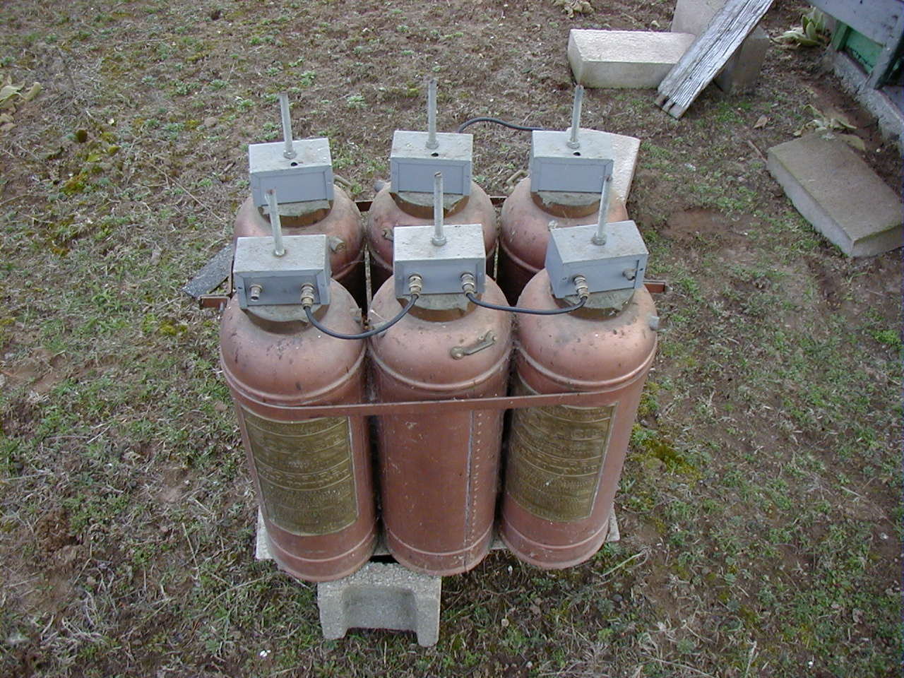
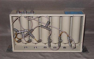
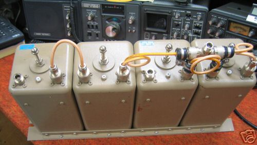
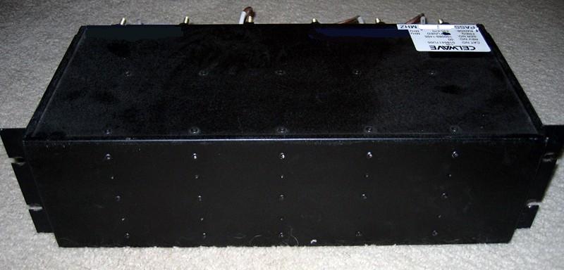
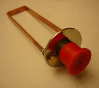
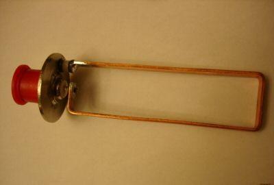
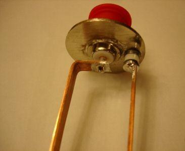
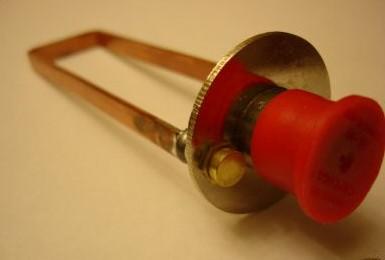
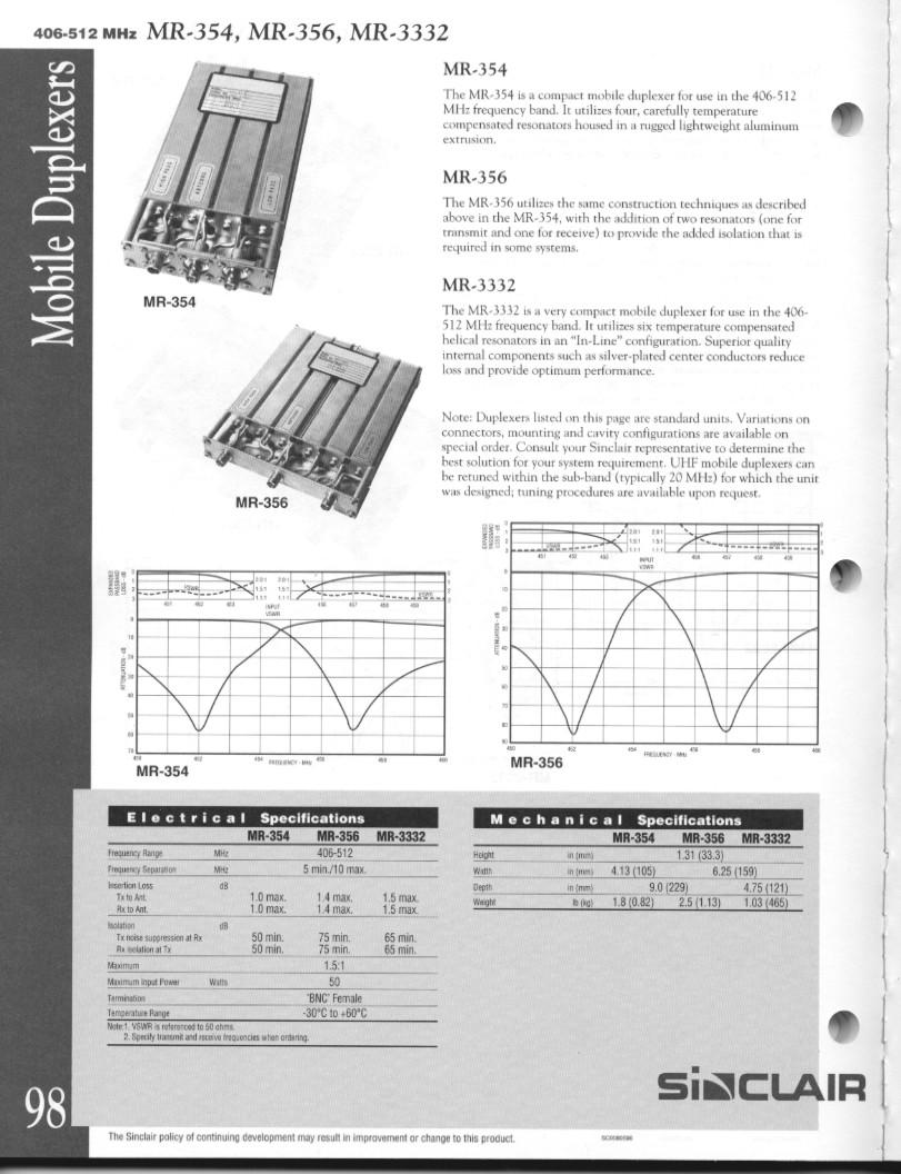
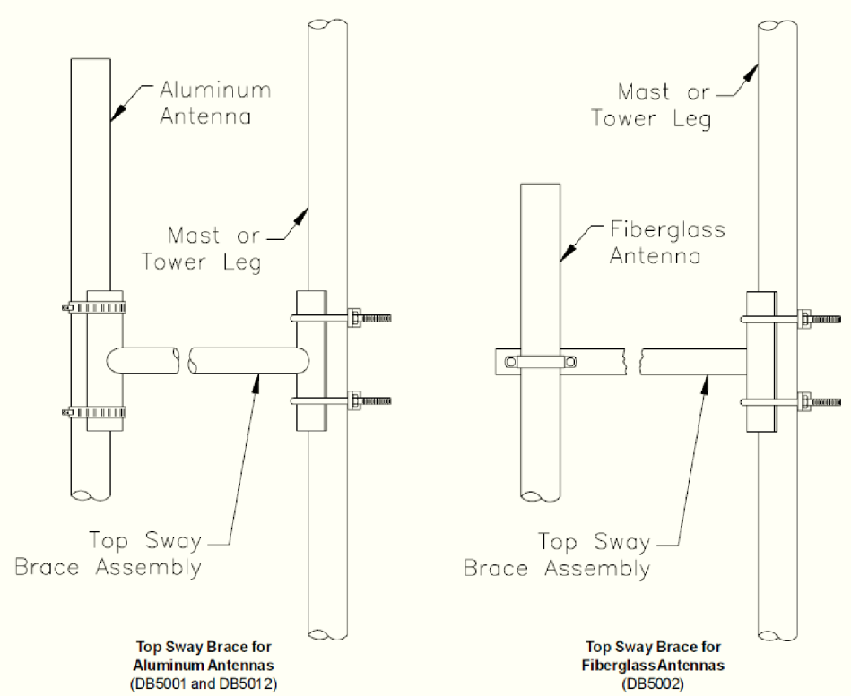
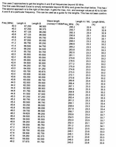
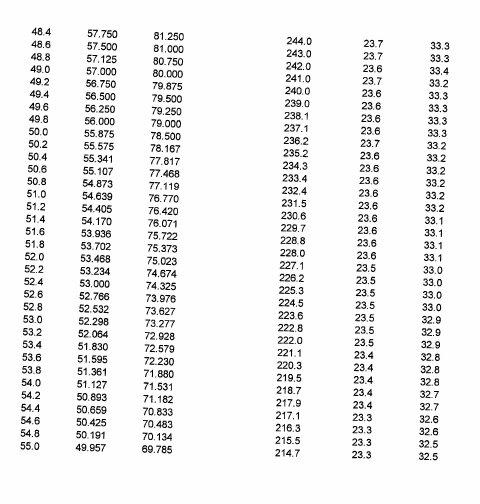
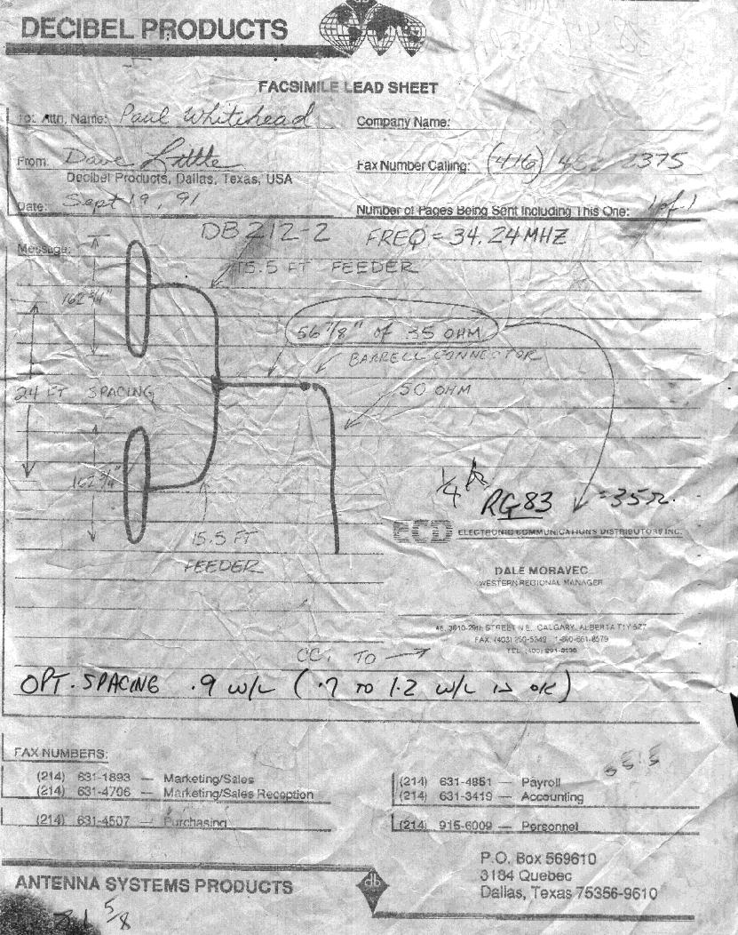
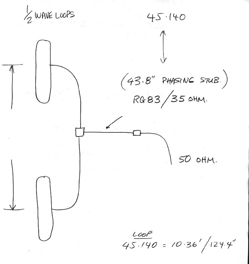
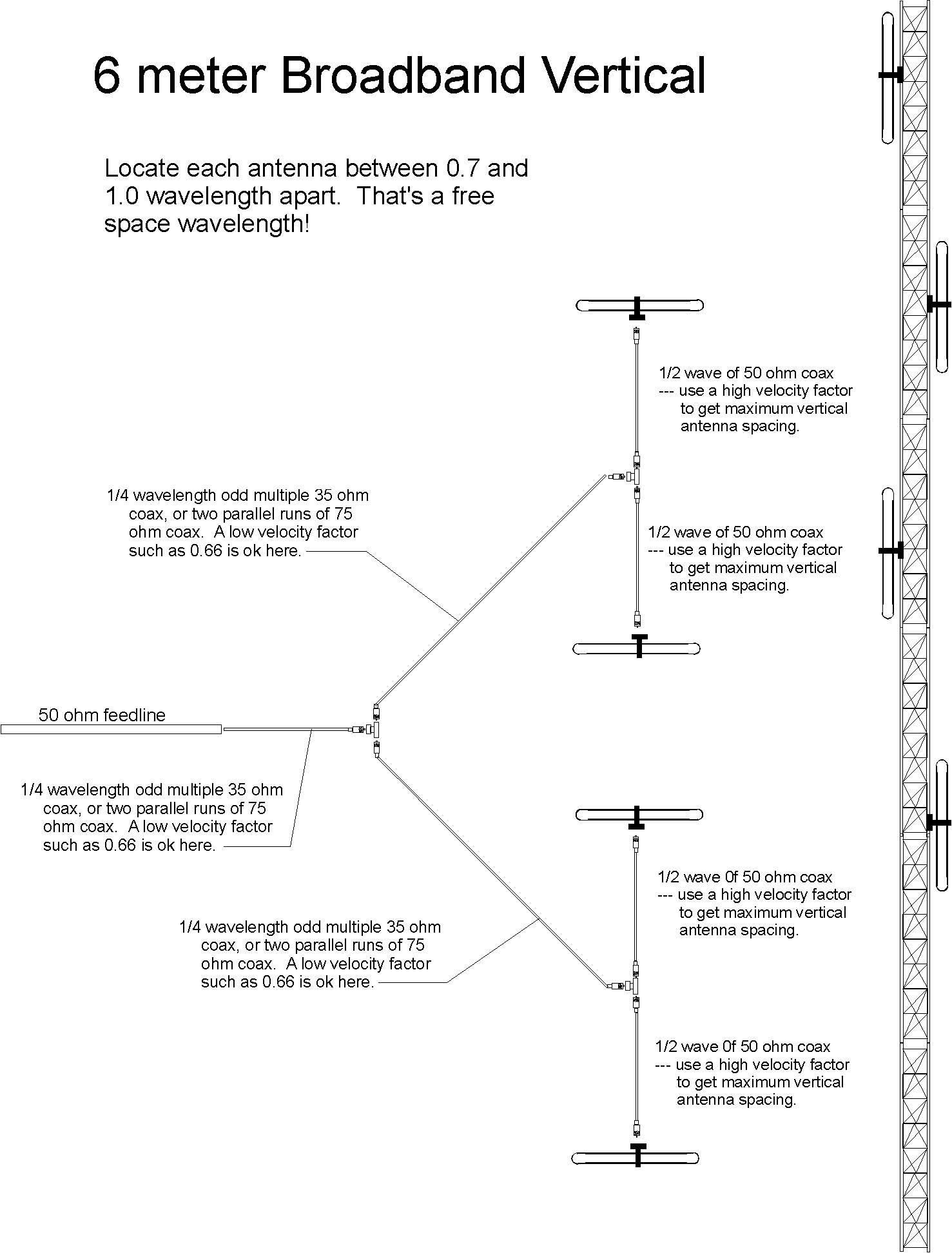
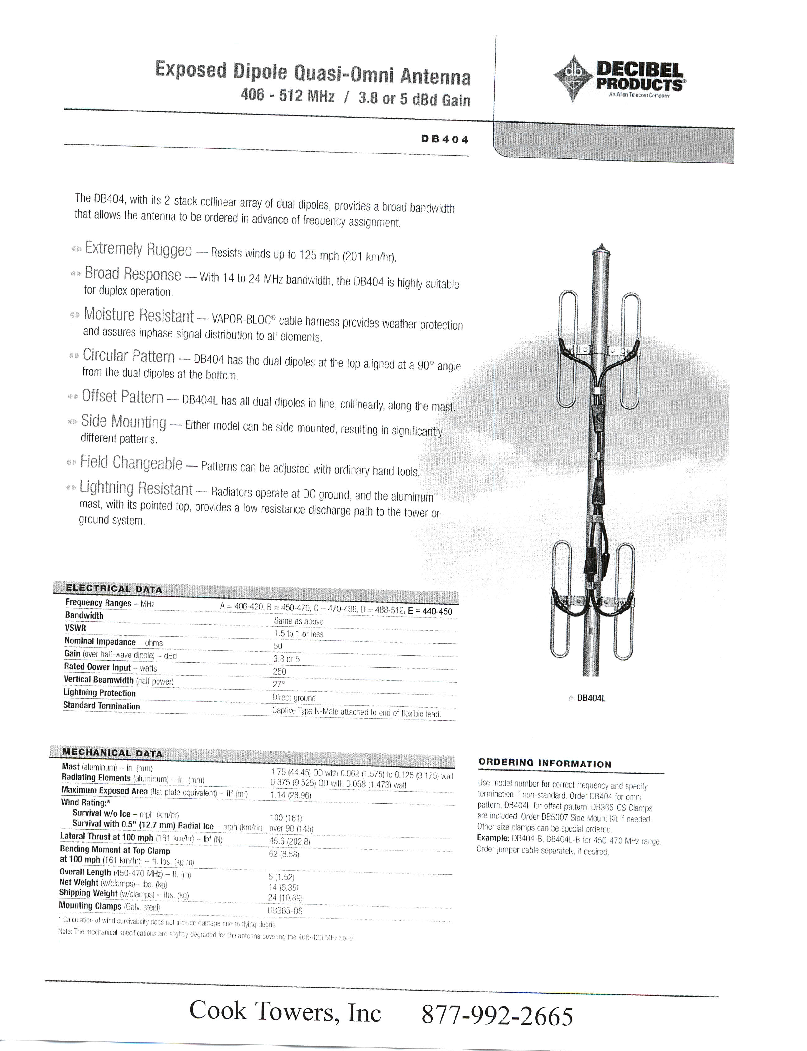
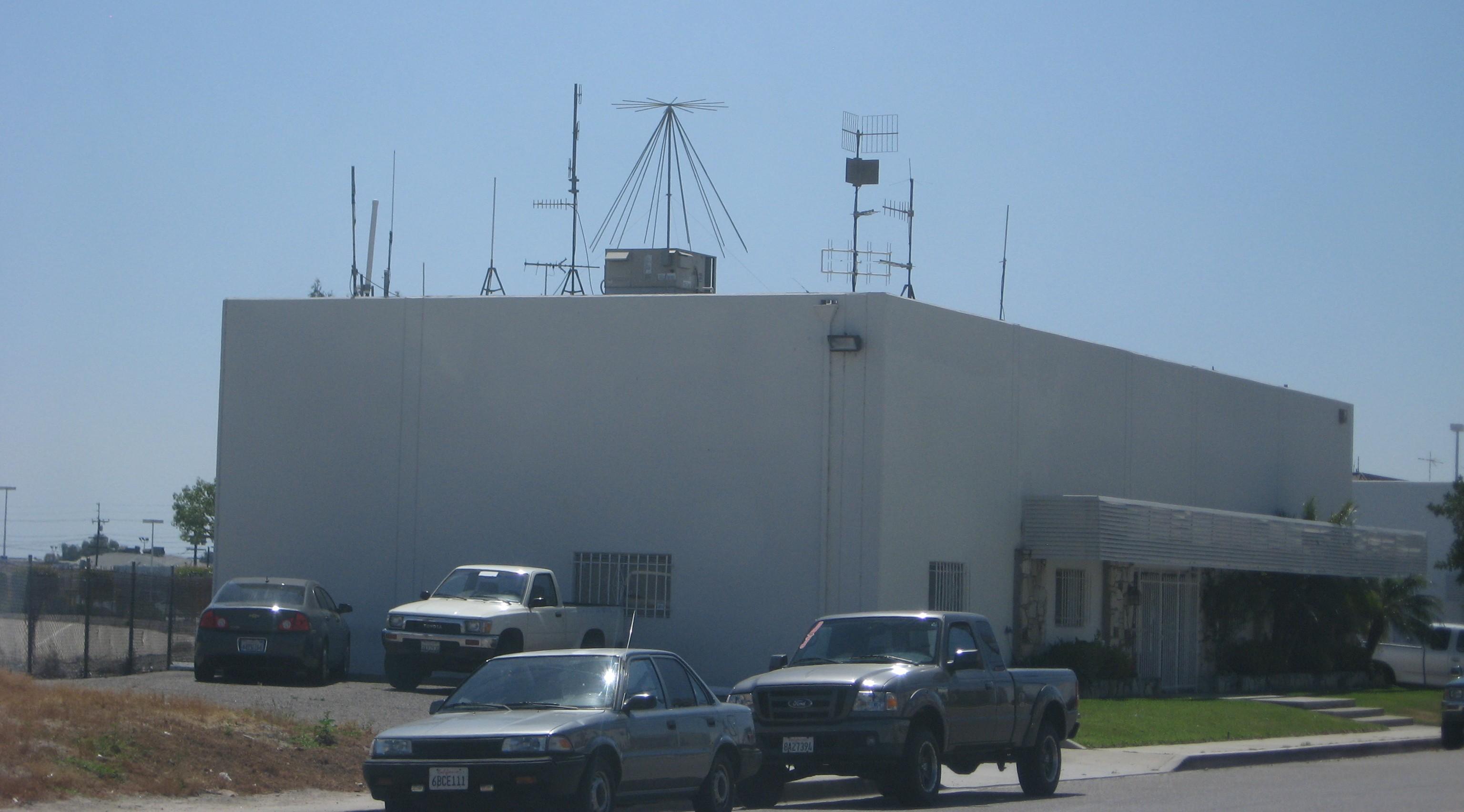
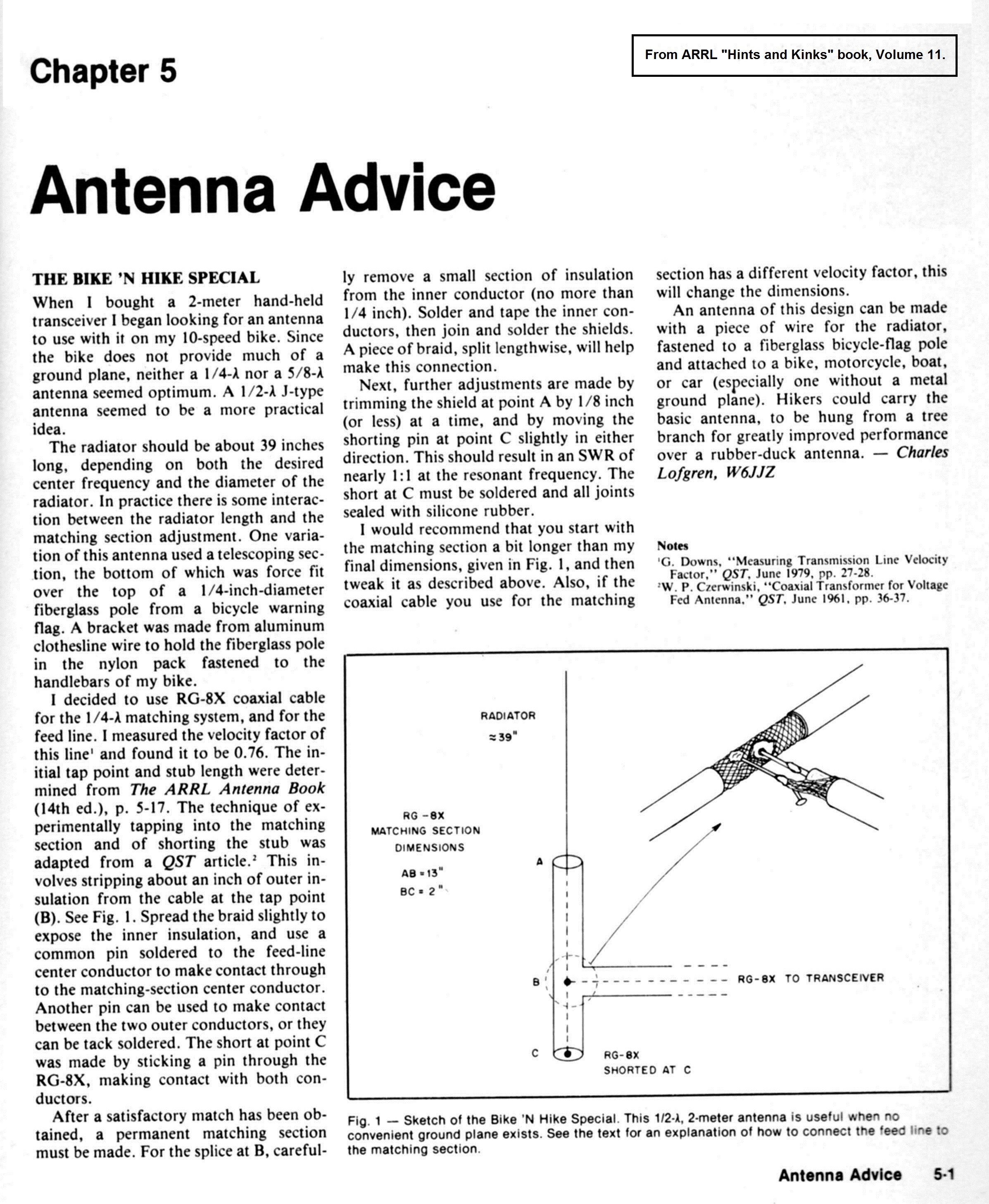