Back to Home
Authored and Currently Maintained by Mike Morris WA6ILQ
Formerly Maintained by Robert Meister WA1MIK (SK)
Graphs at the bottom donated by Kevin Custer W3KKC

|
Up one level (Antenna Systems index page)
Back to Home |
Vertical versus horizontal antenna separation Authored and Currently Maintained by Mike Morris WA6ILQ Formerly Maintained by Robert Meister WA1MIK (SK) Graphs at the bottom donated by Kevin Custer W3KKC |
|
Repeater performance is defined more by RF performance than by audio performance. You can have the best sounding repeater on the planet, but if the user community can't get into it or hear it then it's worthless. Audio performance is covered elsewhere on this web site. Good RF perfomance is dependent first on the antenna system and second on a balance between the receiver and transmitter... you want neither an "elephant system" (all ears and no mouth) or an "alligator system" (all mouth and no ears). The first step in optimizing the RF performance is to maximize the isolation of the receiver from the transmitter.
There are some additional thoughs on isolation in this article: Some thoughts on Repeater Receiver-to-Transmitter Isolation.
Isolation is a cumulative number, provided by the collective hardware that comprises a repeater. Individual units can have good and bad features, some of which can enhance the total, some are neutral, some can degrade the total. For example, a braided feedline instead of a solid corrugated feedline. RF jumpers between the duplexer and the repeater with a loose weave braid versus a 100% shield. An exciter with sharply tuned interstage filtering to cut down on the off-frequency broadband noise. A sharply tuned front end instead of a lumped LC front end in the reepater receiver. A preamp with helical filters versus a lumped gain untuned preamp. A 6-cavity pass-notch duplexer instead of a 4-cavity notch-only model (but watch the insertion loss). A shurted stub between the duplexer and the repeater receiver to reduce the level of the FM broadcast station in the adjacent building. And the list goes on....
Some systems run two antennas, some by choice, some by necessity.
For example, a local 6 meter repeater consists of a receive antenna side-mounted
on a tower at 50 feet - the receive tower is located at a business) and a 6m
recevier feeding a 420 MHz UHF transmitter (1 watt into a 6 element yagi).
The link transmitter is physically located on the tower next to the yagi, all
that goes up the tower is AC power. The transmit site is a 3/4 of a mile away,
consisting of the receive 420 Mhz yagi, the UHF receiver the 100w 6m transmitter
and the 6m transmit antenna (also a side-mount antenna on a tower).
Yes, they could have made up a duplexer from heliax (see
this article), but they feel that they
have a more sensitive system due to no duplexer insertion loss.
A second example: one local commercial tower site has the top crossmember of the 120 foot tower reserved for receive antennas. There are two 403-512 MHz receive antennas for UHF and two runs of 1-and-5/8 inch Heliax feedline (i.e. a primary and spare antenna). Inside the building there is a an AngleLinear preamp panel that feeds a cluster of 8-cavity window filters (first: amateur 440 MHz, second: 455-460 MHz, third: 465-470 MHz, fourth: 473-476 MHz, fourth: 509-512 MHz). Each window filter output feeds an AngleLinear distribution amplifier panel. Overall this system allows one receive antenna to feed the receivers of over three dozen UHF repeater systems ranging from 413 to 511 MHz (the common name for this type of system is a "master receive antenna" or a "community receive antenna"). The transmit side of each group of five repeaters feeds a five-port Sinclair transmitter combiner which feeds a single transmit antenna. All of the transmit antennas are mounted to crossmembers at the 100 foot, 80 foot and 60 foot levels on the tower.
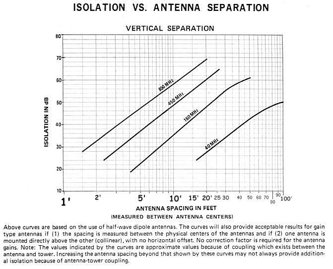
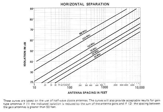
The isolation graphs below date from the late 1950s and early 1960s when transmitters were crystal-based and hence generally cleaner and receivers had tuned front ends but the receive-to-transmit isolation derived from just antenna spacing does not change, it's simple physics.
Do note however, that the size of the antenna needs to be factored into the system... picture a situation where you have a pair of DB208 high band antennas, each of which is over 40 feet long, mounted one above the other on a tower with six feet of space between them. Despite what the graph below says, six feet between a receive element and a transmit element outweighs the 40 feet of separation between the radiation centers... don't expect the over 55 dB of isolation between them that the 40 feet on the graphs below would imply...
The curves below show a maximum of 80 dB for vertical separation and 90 dB
for horizontal. Do not assume that antenna separation alone will provide
a good performing repeater unless you run split site. If done properly,
the separation is additive. As long as you don't have one antenna in the
major lobe of the other you could add a 50 dB of vertical isolation and
15 dB of horizontal and get 65 dB total. In practice, I've found a good
null directly in line with (i.e. under and over) the transmit antenna, and
moving the recieve antenna out of the null can result in less isolation.
Note that nulls are environment dependent - if someone else moves something
on the tower that the null that you carefully positioned your antenna into
may move...
|
|
Back to the top of the page
Up one level
Back to Home
This web page originally created, posted and is © Copyright June 2000 by Kevin
Custer W3KKC.
Separation graphs provided by Kevin Custer W3KKC.
Text, hand-coded HTML and layout © Copyright 2003 and date of last update by Mike Morris WA6ILQ
This web page, this web site, the information presented in and on its pages and in these modifications and conversions is © Copyrighted 1995 and (date of last update) by Kevin Custer W3KKC and multiple originating authors. All Rights Reserved, including that of paper and web publication elsewhere.