| Back |
Diplexers, Duplexers, Cavities, Theory, and More... Compiled, HTML'd and Maintained by Mike Morris WA6ILQ |
Comments, corrections, critiques, suggestions and updates for this page (or any page) are be appreciated.
First... Diplexers versus Duplexers.
Uninformed people sometimes get the two confused and call a diplexer a duplexer, and vice versa.
This is becaue the manufacturers (like NCG / Comet / Diamond in particular), use
the term duplexer on their diplexer products.
Their marketing people really need to use the proper term.
A diplexer (or triplexer or quadplexer), is a bandpass filtering unit, usually L‑C based, that allows multiple transmitters, or receivers on different frequency bands to use a single feedline, antenna, or both. The generic term is diplexer (di=2, two bands / three connectors), but you may hear folks use the term diplexer (or duplexer) to refer to a triplexer (tri=3, three bands / four connectors) or a quadplexer (quad=4, four bands / five connectors.
Note that the average diplexer / triplexer / quadplexer device is not field adjustable - they are designed and manufacturered for a specific frequency range.
Diplexers / triplexers / quadplexers are available in many different combinations of frequency bands. Some generic examples:
1) Separate 2m and 440 MHz radios feed a single dual band antenna (using a diplexer), or...
2) a 6m radio, a 2m radio and a 440 MHz radio feeding a triband antenna (using a triplexer), or...
3) an HF radio and a 2m radio feeding a diplexer that feeds a single coaxial feedline, and on the other end of the cable another identical diplexer breaks the coax apart to separate HF and 2m antennas.
Another example, this one specific: an Icom 706Mk2G radio has two antenna connections, one is for HF and 6 meters, the other connector is for 2 meters and UHF. If you had a separate HF antenna and a 6m antenna, then you would use a diplexer with a breakpoint between 10 meters and 6 meters to split the HF and 6 meters to two separate antennas. The splitting could be done at the back of the radio feeding separate HF and 6m feedlines / antennas, or it could be at the other end of a common feedline feeding separate HF and 6m antennas.
The 2m / UHF connector on the Icom could be connected to a single feedline that drove a 2m / UHF dual band antenna. If you had separate 2m and UHF antennas you would need a diplexer (one with the breakpoint between 2m and UHF) at the far end of that line to split the coax to the two antennas.
And yes, some uninformed people mistakenly call a diplexer a "splitter" or a "combiner" because
it "splits" or "combines" signals into or from an antenna or
a cable. In reality, a splitter (another term is multicoupler) is a lossy in‑band unit that
passes a signal to multiple destinations (picture the device you use to split one TV
coax to two TV sets). Many have an amplifier in line to compensate for the insertion,
loss which can be as high as 14db on a 8‑port unit.
A true combiner is a cavity based device that allows multiple in‑band transmitters to
share an antenna - but with some insertion loss (which can be considerable).
Click here to go to the combiner introduction page.
There are commercial grade diplexers (TX / RX is one manufacturer), and there are ham grade diplexers.
And diplexers can be home‑brewed, one design that became a kit is here:
The Makis Katsouris SV1AFN VHF‑UHF Diplexer (off‑site pointer, opens in a new browser tab).
Two personal opinions from the author:
1) I will not use a commercial ham grade diplexer / triplexer / quadplexer
at a mountaintop or commercial radio site. Ham grade stuff is manufactured to a price target, i.e. as cheap as
possible (to maximize the profits). The price difference between a ham grade unit and a commercial grade
unit is not worth an interference issue that might permanently ruin my relationship with the site
owner or his site manager. Some of my sites are a result of long term friendships (40+ years at one site).
2) I actively avoid all diplexers / triplexers / quadplexers that have
pigtail cables. Every one that I have owned and several that I have looked at or worked on
for other hams have eventually had problems with cable issues... one reason is that the ham
manufacturers use the cheapest coaxial cable they can find - which means off‑brand junk with
thin jackets, thin braid, loose braid weave, thin conductors, and hence a fragile product. And the
coaxial cable may have been cheap becasue it didn't meet specification or pass final inspection.
Then there were the intermittents, shorts and opens. I have found sloppy crimped‑on coax
connectors - one fell off the cable right in my hand - and the diplexer was brand new - I had opened
the package myself an hour earlier. On another occasion I found the center conductor of one pigtail
wasn't even soldered to the circuit board during manufacture (the shield was, how could the
assembler miss that?)... there wasn't any solder on the cable center conductor. On another
occasion the coaxial cable pulled out of the metal diplexer body with the slightest tug. On
the other hand I have never had a physical problem with the ones that have real coaxial connectors
mounted into the diplexer metal housing.
Note that every manufacturer of ham‑grade units uses nickel or chrome plated connectors... and
both nickel and chrome are known intermod generators in an RF environment. On the other hand
I have seen a TX / RX brand unit with real silver‑plated connectors. On a site visit
a few years ago I saw a new tenant installation with a Comet triplexer behind the repeater... The Comet
web site showed that model number with coax pigtails, but the unit in front of me had silver plated female
N connectors in all four locations. It's being used on a remote base system: the 2m port is a XPR series
channel‑steered remote base radio, the UHF port is the repeater, and the 1200 MHz port
feeds a control receiver.
Where a diplexer operates as a cross‑band device (i.e. operates on two or more bands) a
true duplexer is almost always a three‑port in‑band device. The normal purpose of a
duplexer is to allow the simultaneous operation of a receiver and a transmitter on two separate
frequencies in the same frequency band and on the same antenna. A duplexer accomplishes
this by providing isolation between two frequencies: the receive frequency and the transmit frequency
while coupling the receiver and the transmitter to the antenna with minimum insertion loss.
Translation: allow as much as possible of the transmitter's signal to go out to the antenna and prevent
it from having ANY effect on the signal coming in to the receiver.
When shopping for the best performance there is a tradeoff... highest receiver‑to‑transmitter
isolation versus the lowest insertion loss. Naturally higher isolation is better with 80‑90dB as
a practical goal, and naturally 1 dB insertion loss is better than 2 dB. And you always
want to favor your system receiver.
Since a duplexer is made up from multiple cavities, we need to know a little about cavities...
A cavity works because of simple physics based on frequency, wavelength, and the length of a 1/4 wave in coax and / or in a cavity. A single cavity, depending on how it is made and used can be a peak filter or a notch filter. Different cavity designs have different insertion loss and different peak / notch depth characteristics and there is usually a very visible tradeoff between peak height / notch depth and insertion loss. Some cavity designs have one or both of the connectors in the top, others have the connector(s) on the side.
Multiple cavities in series and tuned to the same frequency collectively increase the height of the peak or the depth of the notch.
Duplexers are arranged so that the peak (or notch) from each one is added to the previous peak or notch and the next one by means of critical length cables. This additive characteristic is what makes a duplexer possible. Duplexers are usually made from a collection of one or more "pass" type resonators plus one or more "notch" type resonators to provide the attenuation necessary to allow simultaneous transmitting and receiving. They can also be made using regular band pass filters provided there is adequate skirt rejection. This is usually not the case at frequencies less than 800 MHz because the typical receive and transmit offsets are so small (roughly 0.5 %).
Another way of thinking about this is that there are two common types of duplexers: notch-only (sometimes called a notchplexer), and pass / reject. Various companies have trade names for their particular design, but as this is a general discussion, I'll limit it to these two styles. The notch-only style usually has one adjustment per section, and it serves to reduce or eliminate the signal that it's tuned on. Most mobile duplexers (also called "flat-packs") are this type. The pass / reject style usually has two adjustments per section, one that notches one frequency, and one that passes the other frequency. In many designs these interact. There are usually two or three sections per side: transmitter to antenna, and receiver to antenna. When I speak of the "transmit" side, I'm referring to the sections that are in the half that attaches to the transmitter. Most (but not all) duplexers are symmetrical, i.e. they have the same number of sections per side, and the antenna port is in the center.
With a notch-only style, all of the sections on the receive side are tuned to eliminate the transmit frequency, and those on the transmit side are tuned to eliminate the receive frequency. For example, if your repeater is transmitting on 449.0 and receiving on 444.0, the transmit side would be tuned to notch out 444.0, and the receive side would be tuned to notch out 449.0.
The pass / reject style has notch tuning which works just like the notch-only style, but it also has additional components that attempt to only pass the desired frequency to / from the antenna. Using the same frequencies as above, the transmit side would be tuned to pass 449.0 and reject (or notch) 444.0, and the receive side would be tuned to pass 444.0 and reject (or notch) 449.0. Pass / reject duplexers usually offer better performance but also cost more and are physically larger. You'd usually find these in larger base station repeaters.
On either type, the notch should be around 30-40 dB per section. The deeper the notch, the better. There will also be some loss between the transmit port and the antenna port, and between the antenna port and the receive port. Typically this loss is in the 1-2 dB range. Obviously the less loss, the better.
Unfortunately, saying "duplexer" is like saying "car". They come in various types, makes, models, and performance levels. There are 3‑cavity, 4‑cavity, 5‑cavity, and there are 6‑cavity models (more cavities give a higher level of receiver‑to‑transmitter isolation, but at a cost of increased insertion loss) and I have seen 7‑cavity and 8‑cavity 3‑port units that were custom designs for specific situations. I have also seen non‑symmetrical duplexers, for example 3 cavities on one side and 1 cavity on the other side. In general, the higher the RF level at a site (i.e. how many other systems there are, how close they are (both physically and in frequency), and the power levels involved, the more cavities you need).
I've also seen an 8‑cavity 4‑port duplexer (it was a custom order) that allowed a
144.39 MHz simplex APRS gateway transciever to share one antenna with a 147 MHz range
repeater. And you may not need a duplexer at all if you run a split site system at a low RF level site.
Depending on circumstances even a single site system can be built with no duplexer at all (see the
"Some thoughts on Repeater Receiver‑to‑Transmitter Isolation" article
elsewhere on the Antenna page).
And there is a second reason that you might not need a duplexer... I have commerical repeater installations
at multiple sites... At several sites there are master UHF receive antenna systems (roughly 440‑506 MHz)
that feeds all of the repeater receivers. Most of those sites also have 5 port transmitter combiners. The antennas
on the ham combiners are 445‑455 MHz range antennas, and the 5 ports have
transmitters from 446.5 through 454 MHz connected to them (the amateur UHF repeaters in
southern California are low‑in / high‑out... that makes combining much easier).
And to continue the used car analogy above, used duplexers can have problems just like used cars. Unless you trust the used duplexer seller you will want to have your radio mechanic test it out before you buy it. As just one example - many duplexers have a variable capacitor as part of the tuned circuit (the "loop" assembly) on each port. Usually these are a precision glass vacuum variable capacitor. A new (replacement) one of those capacitors can cost you over US$150 (2004 prices)... and then you get to install it. And the physical effort involved in replacing one can be anything from simple to outrageous depending on how the cavity was built.
Duplexers expect to see a 50 Ohm load on every port, and many transmitters, many receivers and some antennas are not. A duplexer is 50 Ohms only at resonance, anywhere else it is reactive. The attached feedline is 50 Ohms, and the receiver or transmitter is SUPPOSED to be 50 Ohms. If it is not, the most common way to "fix" the problem is to use a "magic" length cable - but the right way is to fix the radio so it truly is 50 Ohms.
The proper way to tune a cavity or a duplexer is to use a spectrum analyzer and a tracking generator. You tune one side at a time, and you always have a 50 ohm load (or pad) on the third port. Many test procedures say to use 6 dB or 10 dB 50 Ohm pads between the test equipment and the cavity (or the endmost cavity of the duplexer), as that ensures that the pad "masks" any non‑50‑Ohm‑impedance in your test equipment. This ensures that the duplexer is really tuned to precisely 50 Ohms. You can remove the pads for the final tweak for the deepest notch(es) or highest peaks since by that point you are at 50 Ohms.
Many folks that take a duplexer that is tuned on the bench and then install it in a system discover that the duplexer is "mistuned" - that they have to make adjustments to get the same performance that they had on the bench. Well, that is telling you that your radios (or your antenna system) is / are NOT 50 Ohms. The transmitter can be fixed with a "Z Matcher". Then retune the duplexer. Once the duplexer is tuned properly it should NOT need ANY adjustments from the bench to in service at the site (except for the bumpy 14‑mile‑long four wheel drive road - and that's why you take the pads and the service monitor with you to verify the tuning on site). And you (try to) drive that 4wd road "gently".
A posting on the repeater‑builder mailing list a while back made the comment that the GE MASTR II UHF transmitter output impedance was mostly 50 Ohms resistive, but with a capacitive or inductive component whose value depended on what company made the output transistors (and this characteristic is not limited to GE equipment). In the early days of the MASTR II large fleet operators were having an unusually high number of station and repeater power amplifier failures. One large user that I am aware of had eight repeaters and was losing roughly one PA per month. After GE had several engineers investigated the problem they came up with a two‑pronged fix. Solid state power amplifiers do not like reactive loads, and the engineers found that the best solution was a pi‑network output matching stage followed by a circulator to protect the output device(s) from an unmatched load. GE had Decibel Products develop a "Z Matcher" device which functioned as the output tank circuit that the original transmitter designer had left out. The second prong of the field fix was that GE ended up buying a circulator for each repeater transmitter and this solved the rest of the problem (this situation is why the Motorola MICOR line has a factory‑installed circulator in every PA deck - even in the mobiles! And I have seen re-purposed Micor mobile circulators in use on other transmitters). As mentioned above, every circulator must be followed by a low pass filter (some installations use a pass cavity, which itself might be separate or part of a pass‑notch duplexer).
Unmatched loads did not start with solid state PA decks. Feedlines over the years have included 35 Ohms, 50 Ohms, 75 Ohms, 93 Ohms, 125 Ohms, 300 Ohms, 450 Ohms and probably others. As mentioned, one way to transform impedances is to use a "magic" length of the right impedance of coax as a matching transformer. The cable length between the end cavity of the duplexer and the transmitter is NOT supposed to be critical, and if it is then you have an impedance problem. While the most common situation is between the transmitter power amplifier and the duplexer, the same situation can happen between the receiving antenna and the receiver, or between the duplexer and the receiver... it is just much less visible. Matching the transmitter to the duplexer is covered in this article Cabling lengths between the Duplexer and Radio Set. Despite the article title, there is a lot of impedance matcher (usually called Z‑matcher) info in there.
Tony King W4ZT (SK) has some information on the Z‑matcher that GE built into the later MASTR II station power amplifiers at the W4ZT Z‑matcher page. The closeup photos show how GE simply replaced the station antenna relay with the Z‑matcher daughter board (prior to the Z‑matcher it had been replaced with a jumper).
The schematic to the GE Z‑matcher is here. It's part of LBI-30201G.The tuneup info for the DB Products Z‑matchers can be found here.
Back to duplexers...
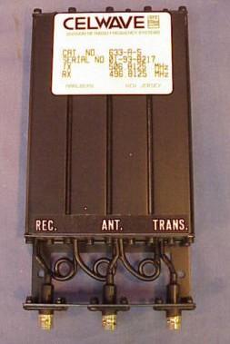
As said above a duplexer is made up of a number of cavities and a number of critical length cables beteeen them. Each cavity adds to the total transmit‑to‑recieve isolation provided by the assembly. Note that duplexers are initially tuned and the ports labeled at the factory. Most are labeled "REC", "ANT" and "TRANS", or something similar (see this photo). This can be misleading! Duplexers are built with a "higher" frequency side and a "lower" frequency side, and the coupling loops and inter‑cavity cabling are selected for those frequencies. The application an amateur has may conflict with the original port labels. Most commercial repeaters (definitely on UHF, usually on VHF) receive on the higher frequency and transmit on the lower frequency (called "high‑in"/"low‑out", whereas UHF amateur repeaters can swing either way (but there is good engineering theory to support low‑in"/"high‑out).
You need to look at the original label of your notchplexer and note if the receive side is the higher of the two frequencies, or if the transmit side is... and keep the high / low relationship the same as you retune it. You may end up using the original receive side as your transmit side. Some manufacturers, including TX / RX call the sides "channels", and their documentation refers to the "high channel" and the "low channel" and the "isolation between channels".
Personally, I remove the factory "Receiver" and "Transmitter" labels and replace them with my own permanent labels reading "High Side Pass / Low Side Reject" and "Low Side Pass / High Side Reject", then I add temporary "Receiver" and "Transmitter" labels for each application. This is expecially true on UHF commercial and GMRS frequencies (+ offset) and on UHF amateur frequencies (- offset in Southern California, Arizona, Nevada, Denver, and many other areas). Some duplexer manufacturers have adopted better markings that read "Pass Low, Reject High" on one side and "Pass High, Reject Low" on the other.
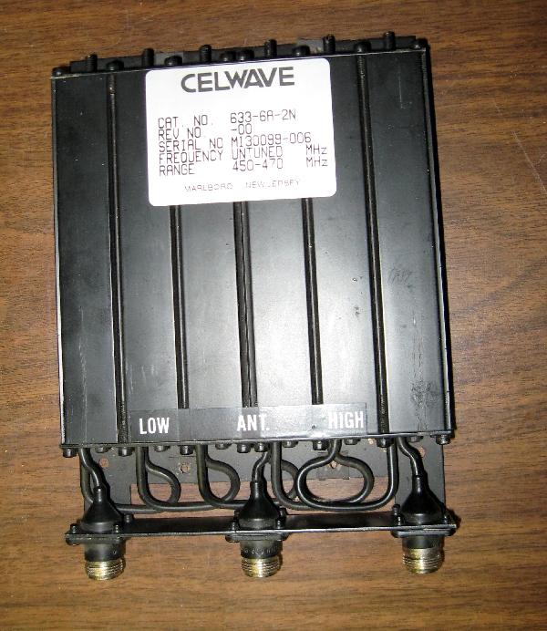
Interestingly, if you order a untuned duplexer it arrives with labels that are almost appropriate (it doesn't say "pass" or "reject")... see this photo.
The cable type and length between the cavities in a duplexer is very critical, to the eighth of an inch (about 3 mm) at UHF, and the actual length of any one cable is dependent on three factors: (1) the cable velocity factor, (2) the length of the coupling loops inside the cavity, and (3) the frequency involved. On a 600 KHz offset 2 meter duplexer the frequencies are so close together that the receive side and transmit side lengths are usually the same, however on a VHF commercial 5 MHz (or more) offset or on a UHF duplexer the optimum length is visibly different between the low and high side. The lengths are also different depending on the length of the loops inside the cavity, and if you are at 415 MHz (USFS links), 425 MHz, 435 MHz, 445 MHz (all ham band), 455 MHz, 465 MHz, 475 MHz (all commercial 2-way), 485 MHz (public safety in southern California) or 510 MHz (some commercial 2-way and a few public safety).
From an email to repeater‑builder:
While it is fairly straighforward to calculate the wavelength in a certain piece of coaxial cable, the length of an intercavity jumper cable on a duplexer is only one portion of the whole length that must be considered. The coupling loop inside the cavity has length that must be added - and that depends on the frequency and the design of the loop. On UHF may amount to 5 to 6 inches, and also varies among the many manufacturers of duplexers. The cable lengths shown in the chart for any particular duplexer have been corrected to include the lengths of the connectors plus the coupling loops or probes inside the cans, and as a result the cable lengths by themselves will not directly correlate to a portion of a wavelength.
From another email to repeater-builder: (note that EMR, REMEC, TX / RX, Sinclair and Cellwave are all manufacturers of cavities and duplexers):
A technician at EMR once told me that he had racks of pre-made jumper cables in 1/4 inch increments, and although he had tables giving him the typical starting points, he would try jumpers above and below that length to achieve the optimum match between each pair of cavities. I have heard pretty much the same story from the factory-floor techs at REMEC, TX / RX, Sinclair, and Celwave.
Likewise the lengths of the cables between the antenna "T" fitting and the end cavities (some folks would call them the "middle" cavities) are frequency dependent and are a critical length, and usually a different length than the intercavity cables. The "T" fitting in the center of the duplexer is critical, and can take any one of several forms. Sometimes it's a special made‑for‑the‑job device that combines a female connector and a "T" fitting (making up a "T" cable), sometimes it is made up of connectorized cables, a simple coax "T" fitting and maybe a barrel connector. Sometimes you find it miscabled, as shown in the article here. Look at the fifth photo, and the last photo.
Some folks run a "split duplexer" without the "T" fitting and cables (or "T" cable), with one antenna connected to the transmit side of the duplexer, and a second antenna connected to the receive side (or the receive antenna may be a one port from the multiport splitter on a community receive antenna). If you find a "split" duplexer and want to go back to the normal configuration then don't be surprised if you have to acquire a replacement center "T" cable. More than once I've seen the situation where it was obvious that the installer simply removed the "T" cable, and ran receiver and transmitter cables right to the connectors on the end cavities. Other times he removed it and tie‑wrapped it to the intercavity cables. More than once I've had to acquire or manufacture a T‑cable for a duplexer that arrived with it missing. Please folks, if you aren't using the T‑cable just tie‑wrap it to the duplexer harness !
Note that many duplexer assemblies have cavity adjustments that are wider in frequency than
their cabling harnesses - for example if you move a VHF duplexer from 160 MHz or 170 MHz
to 2 meters you will find that the cavities will generally go there (as long as the adjustment
rods have not been cut off) but you will usually have to aquire a new harness, or lengthen the old
one. One trick to see if lengthening the harness is the correct option is to add an elbow
adapter (silver plated!) to one end (or even both ends) of each cable and test. Depending on the
internal construction of the particular elbows just adding one elbow can add 1/2 to 1 inch (13 to 25.4 mm).
Hams that are moving a 511 MHz, 482 MHz or 470 MHz duplexer to 440 MHz will
have the same type of harness cable length problem.
DO NOT use the elbow‑extended cable as a long term solution, you need to buy or build the correct
length harness.
Cabling: Double‑shielded silver‑plated coax is the best thing to use to connect a cavity to an adjacent cavity in a duplexer, and to connect a radio to a cavity or to a duplexer. For example, C17/RG‑214 has two braids made up of individually silver‑plated strands and a silver‑plated center conductor for maximum noise rejection. Avoid any coax that has disimilar metals rubbing against each other such as LMR‑(any 3‑digit or 4‑digit number) or Belden 9913, both of which use an aluminum foil shield rubbing against a raw copper braid shield. Many amateurs have purchased LMR‑400 or similar cable, installed it, and it works fine (for a while). They just rave about how good it is. Then anything from 9 months to 5 years later they find themselves taking it down as the cable itself causes "duplex noise" (see the article on this page titled "Help!! I have a crackling noise in my repeater" by Kevin Custer W3KKC). The expensive LMR cable gets reused somewhere else - somewhere that it is not in duplex service. Maybe on an HF station. RG‑142 and RG‑400 are both a smaller version of RG‑214 (but sharing the same construction) and can also be used (but see the article on this page titled "Double Shielded Coax Cable, the differences between RG‑142 and RG‑400, and why you DON'T want to use RG‑142..." by Eric Lemmon WB6FLY). My personal preference is to use mil‑spec RG‑214 or RG‑393 as the antenna‑to‑Heliax jumper at the top of the tower, nothing but Heliax and Superflex on the antenna side of the duplexer and nothing but Superflex and RG‑400 on the radio side. Yes, it's expensive, but like my late father used to say about hand and power tools, "Buying quality only hurts once". Good quality cable with the right connectors is going to be low loss and last a long, long, long time, and it's one less thing to worry about. If you have to use coax in a duplex situation then look at RG‑214 or RG‑393 for the larger diameter (i.e. the size of RG‑8 / 213 / 214) and RG‑142 or RG‑400 for the small diameter (RG‑58 size). All are double shielded with silver plated shields and will not cause duplex noise.
The type of cable that is used between the duplexer and the receiver and between the duplexer and the transmitter is important. Many manufacturers scrimp and use cheap single‑shielded cable, and in many cases get away with it. The Motorola GR300, GR400, GR500, CDR500 and CDR700 packaged repeaters and many of the Yaesu/Vertex VXR series repeaters were (still are?) supplied with single‑shield RG58‑grade jumpers inside the cabinet, and this allows random low level desense to occur. Replacing the factory jumpers with RG‑142, RG‑214, RG‑393 or RG‑400 double‑shielded coax eliminates that. And when you do make cables, make them with the correct silver‑plated connectors on each end, so that you do not have to use any adapters. Use a right‑angle connector where you need it rather than a normal connector and a right angle adapter. All it takes is one chrome or nickel plated connector or adapter to ruin your day.
Quality duplexers do an excellent job of isolating receivers from transmtters within their
design range. But look at the spec sheet! For example a RFS (PD) 526‑4‑2 is only
specified for 435‑470 MHz. It has great performance curves inside that design range.
But the curves don't go down to the FM broadcast band or up to the high TV channels, or to
800 MHz, or 900 MHz. And in many areas there are LMR system transmitters at 471-473 MHz.
Hint: you need to measure your duplexer performance against every other transmitter at
the site, even those paging transmitters in the adjacent building!
I'm suggesting you do this because of bad experiences:
a) We had a major problem at one site after an 900 MHz paging system was installed in the next building over. It was a simple case of receiver overload. The PD‑526 by itself just wasn't enough to keep stuff above 470 MHz out of the system receiver. A pass cavity installed between the duplexer and the receiver fixed it. The tech that took care of the 900 MHz system was a ham and helped us determine the problem (he was worried that one of his transmiters had a spur).
b) At another site there were public safety systems on 482 MHz transmit / 485&MHz receive in an adjacent building. Again, the duplexer on the amateur system had very little attenuation on frequencies out of it's design range.
c) At a city public safety site there is an amateur radio system from the local university. The ham system was (and still is) a GE MASTR II and uses a pass / notch duplexer (a PD 526) that does a wonderful job at 440 MHz. In the early 1980s the local sheriffs went from 39 Mhz to 482 MHz. As soon as the 482 MHz transmitter lit up the ham system got clobbered. The PD526 just didn't have sufficient isolation at 470-490 MHz frequencies and they skated on through. Again, a simple case of receiver overload. It took a 440-450 MHz bandpass filter (then from DCI - now from OCI) between the ham antenna and the duplexer to fix it.
d) At a another site an FM broadcast transmitter was the issue - the 5th harmonic of an FM broadcast transmitter that is operating between 88 and 89 MHz can affect a UHF repeater that receives from 440 MHz to 445 MHz (and likewise 89 MHz to 90 MHz for receivers between 445 MHz and 450 MHz). It doesn't take much to generate harmonics! Remember that an FM broadcast transmitter has ±75 kHz of deviation and by the times it's multiplied by 5 it becomes ±375 kHz deviation... Your 5 KHz wide receiver will not see it as anything but desense! You will need a spectrum analyzer to diagnose that!
In each of the cases above the offending system was operating properly, it was a simple receiver (or preamp) overload issue and ssome additional isolation handled the problem.
Pass‑notch cavities (and the duplexers made from them) have a quirk that can cause you some unexpected problems. Picture this situation: you have a transmitter connected to a carefully tuned cavity with the pass adjustment peaked on the transmit frequency and the notch is centered on the receive frequency. Then a new somebody on the tech committe gets the smart idea to "touch up" the tuning...
He thinks that it was out of tune because he's now seeing a few watts more going to the antenna - but the system performance drops. And he doesn't know why. Or maybe he doesn't see a performance difference, so he thinks that his tweak didn't do anything or maybe the previous guy didn't do a very good job, or maybe it really needed tweaking. What he doesn't realize is that before he tweaked he used to have have 12 to 18 dB of headroom but now he has maybe 3 or 4 dB (but he doesn't know that because there was no visible or audible change). But when winter comes and the ice builds up on the antenna things change, and the system now has a case of desense. But he doesn't realize that turning the knob(s) 4 or even 6 months earlier and having desense today are cause and effect... (and it takes snowmobiles, a Sno‑Cat, snowshoes or even a helicopter to get to the site to fix it... and you never go to a site alone, so it inconviences two or more people. And the last time I priced a helicopter for a hill trip (mid 1970s) it was over $5 per minute, flying or sitting... It's a lot more $ now). And the helicopter company charges from the time they leave their base until the time they return to base.
What happens is that as soon as the person turns any one of the knobs on the cavity the peak moves and since the notch tracks the peak the notch in that cavity also moves... and the total rejection notch depth of the three cavities on that side of the duplexer is now shallower. If the total notch depth is not not deep enough, the receiver is desensed.
Once a cavity or duplexer duplexer is properly tuned to your frequency there is NEVER any reason to adjust it!
I've seen duplexers that haven't been touched since installation (and some were installed in the late 1960s and early 1970s). A lot of folks that I know actually tie‑wrap a note to the tuning rods - and the note says (in very strong, coarse and blunt language) not to touch the tuning for any reason, and if necesary to contact (someone's name - usually the head of the tech committe, or the system owner). Some folks remove the knobs in addition to posting the note. And there's a reason Sinclair offered a steel cabinet in their older catalogs for their high band duplexers - and that cabinet had either bolt‑on front and rear panels or optional locking doors.
Most "mobile duplexers" are reject‑only and are sometimes called flatpacks, notch‑only, or notchplexers. Some are 4 transmit and 4 receive (8 cavity), some are 3+3, and I've seen 2+2, 3+2 and 3+1 configurations.
A note on small mobile duplexers from Eric Lemmon WB6FLY (SK): (editors note: Southern California uses low‑in, high‑out on the UHF repeaters)
Most UHF mobile notch‑only "flatpack" duplexers will work fine below 40 watts at a 5 MHz split – but their performance rapidly deteriorates when operated outside of their designed frequency range and / or power limits. For example, a commercial‑band mobile duplexer that was manufactured to operate in the 450‑470 MHz band will likely perform poorly in the 440‑450 MHz Amateur band. Although such a duplexer may SEEM to be working in the Ham 70 cm band, it may display shallower notches or have excessive insertion loss that the owner may not realize. That's because the internal coupling loops are set for the specified frequency at the factory during manufacture and not readily adjustable by the owner.
I once tried to use a commercial‑band mobile ("flat pack") duplexer on a 70 cm ham radio pair in a portable repeater, and was disappointed in its performance ‑ especially in the receive sensitivity at 441 MHz. I then ordered a new Celwave duplexer of the same model, but factory‑tuned for my amateur frequency pair. What a difference! Once the new duplexer was installed, the receive range of the club's portable repeater was significantly improved, with no other changes.
Other people report no problems with moving flatpacks to 440 MHz or even 420 MHz, it all depends on the original design and construction of the particular duplexer. A good test, and a real eye‑opener, is to measure the insertion loss separately on each side of the unit, at the original frequencies on the label and then again on the your new frequencies. In most cases the differences in the numbers will really surprise you. And remember that the effective repeater performance is limited more by the repeater receiver that the repeater transmitter.
Remember that reject‑only / notch‑only duplexers (also known
as "notchplexers") are not appropriate for high level RF sites as they provide zero
protection for the repeater receiver from any other transmitter – they are
designed to protect a single receiver from a single transmitter, and nothing else (and remember
the "higher side" and "lower side" rule mentioned above). The notch
that protects the system receiver from the system transmitter is not going to have ANY effect
on any other transmitter frequency... that paging transmitter, that FM or TV broadcast station,
the spur from the cell site next to you, or anything else.
My personal experience says that if you are going to locate a quality repeater system at a busy
site you generally need to use a quality pass‑notch duplexer with at least six cavities.
If the site has a master receive antenna you probably won't need a duplexer, instead you may
need a pass cavity between the distribution amplifier and your receiver, and a second one
between the output of your transmitter circulator and the transmit antenna.
Another way of saying this is that a notchplexer provides no protection from
any frequencies other than those notched.
If you're just starting out, I strongly suggest that you read the first dozen or so articles in the Duplexer section on the Antenna page, especially those by Jacques Audet VE2AZX, John Portune W6NBC and by William F. Lieske. Yes, there is some repeated material between the articles, but if you're new to duplexers, it won't hurt. When you have multiple people writing on the same topic (any topic) some repetition is inevitable. Collectively those articles will give you a basic education on duplexers.
Contact Information:
The author can be contacted at: his-callsign // at // repeater-builder // dot // com.
This web page created and first posted 14-Oct-2004.
This content on this page was split from the main Antenna Systems page 12-Nov-2011.
Layout and hand coded HTML © Copyright 1995 and date of last update by Mike Morris WA6ILQ
This web page, this web site, the information presented in and on its pages and in these modifications and conversions is © Copyrighted 1995 and (date of last update) by Kevin Custer W3KKC and multiple originating authors. All Rights Reserved, including that of paper and web publication elsewhere.