Back to Home page
Tree Suspended Vertical
By John Haserick W1GPO

|
Back to Antenna index Back to Home page |
Considerations for a Tree Suspended Vertical By John Haserick W1GPO |
|
Purpose:
This article shows how one tree suspended antenna was made to work well (after four revisions), and should be as reliable as the tree limb it is attached to. The reader will be able to take advantage of an unused resource in their yard to boost performance for other vertical antennas. It might even grow in height on its own, the dream of us all!
Unfortunately we are very often unable to place a tower at a residence upon which to mount a vertical VHF-UHF antenna. Often we have to settle for a roof, gable, or chimney mount and deal with interference to and from equipment inside the house, as well as blockage of RF by higher adjacent houses. Many older neighborhoods have at least 80 ft high trees that will support a vertical with a top height of up to about 65 ft. These antennas can be sprayed with Rust-Oleum Deep Forest Green Camouflage paint to render them almost invisible, even in winter.
The following photos show the various details of the hanging antenna system. Click on any photo for a larger image.
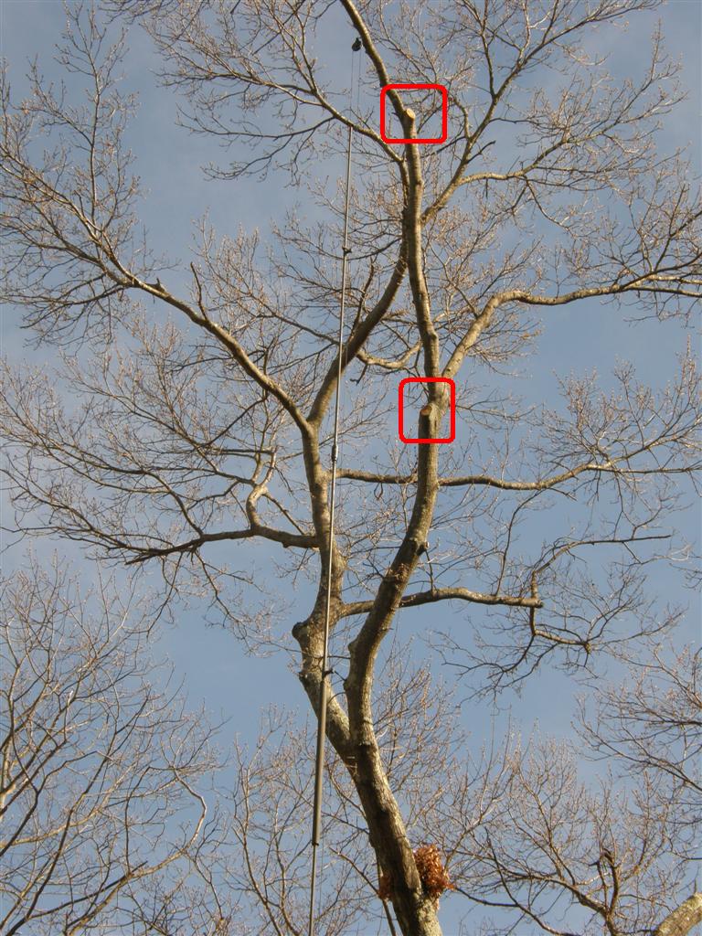
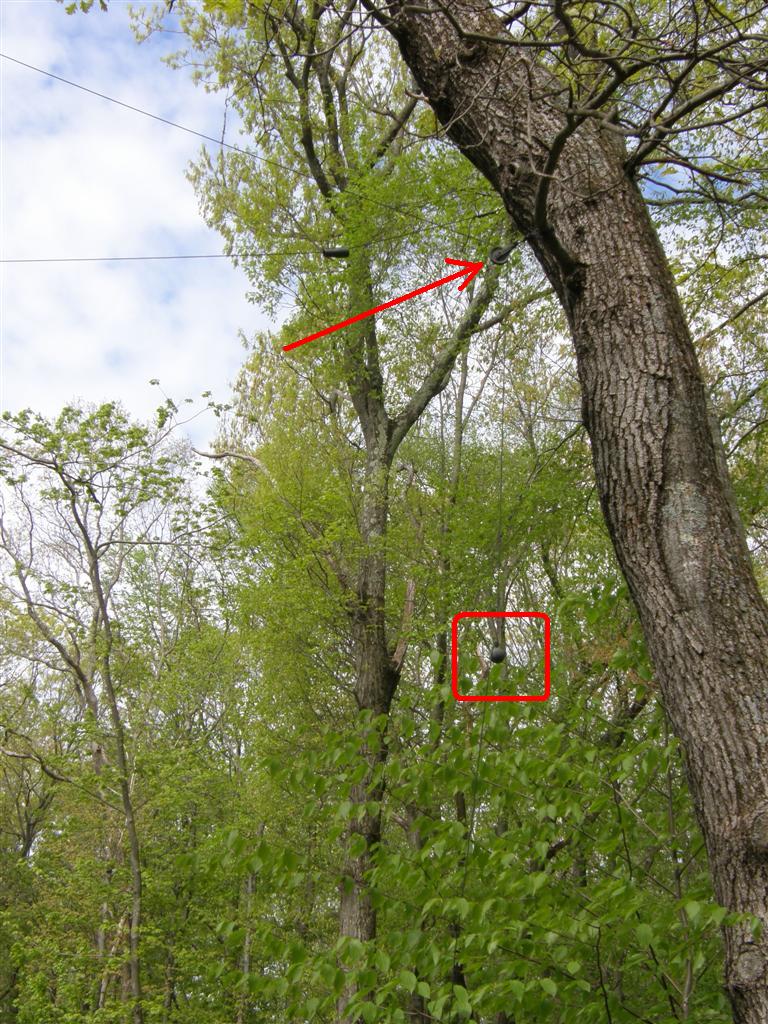
Note the two limbs that were removed below the antenna fastening point.
The top of this vertical is at 65 ft attached via a screw hook mounted pulley to a 3-1/2 inch wide oak limb that had two lower limbs trimmed off to enable more of a load and also keep leaves and branches away from the antenna.
The best method is to hire a tree company with a bucket truck or machine as was done here. That can cost more than $300 but it's still much less than installing a tower. Another method is the traditional method of shooting a line over a limb. Either way, find a tree and limb that does not move as much in a wind as the others, and the antenna will be at least 1/4 wavelength horizontally from parts of the tree in a high wind, to minimize detuning. The big advantage here over a tower is that your antenna can be close to the property line.
It is absolutely necessary to enable the antenna to move in the wind with the tree limb. This means the ground end has to move up and down, as do the guy ropes. We used an 8 ft 5/8 inch diameter ground rod embedded two feet deep into fast set concrete for stability, and a weighted-with-concrete PVC sleeve to move up and down over the rod vertically +/- 3 ft. Two and 1/2 inch diameter plastic Everlast clothesline pulleys mounted several feet out from vertical guy anchors (other tree trunks in this case) with 20 oz lead cannonball sinkers (purchased at a sporting goods store) allowed the guys to move as needed, without adding too much weight to the antenna, but still limiting horizontal sway of the bottom of the antenna, and also preventing antenna twisting in the wind.
Base of 3/4 inch PVC conduit, 1-1/4 inch pipe and concrete-filled four inch and six inch PVC pipe over ground rod. Rope fastened to black steel pipe with three hose clamps, coax to both 3/4 inch PVC and steel pipe with tape. Note original weighted guy method in background also used 3/4 inch PVC over guy rod. This was replaced by a better method of just weighted sinkers, to reduce any ice load.

3/4 inch conduit joined at bottom of flange to the 1-1/4 inch steel pipe through a 1-1/4 inch Schedule 80 aluminum nipple with three nylon 1/4 inch bolts.


Four bolts through the flange center the four inch PVC pipe coupling that was Gorilla-glued to the flange. These bolts also act as an additional bond of the concrete to the PVC pipes.
For this antenna, a second horizontal set of guy ropes (3mm MastrAnt-DX Engineering) at the bottom of the antenna was needed to reduce horizontal sway of the coax / vertical rope (4mm MastrAnt).
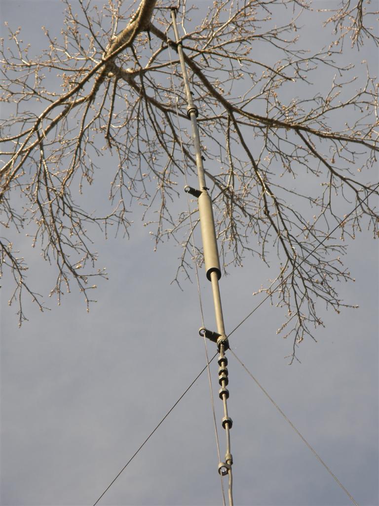
Attachment of the upper guys and ferrites. It does not show well, but the coax is also joined to the bottom antenna PVC tee with two ropes, to relieve tension on the PL-259 connector up inside the antenna at the coil. A hose clamp is around the bottom outside of this PVC tee for added guy strength.
A plastic shower curtain loop allowed the coax / vertical rope to move up and down inside the loop. Also in picture note a few PVC electrical couplings taped to the coax with vertical rope through the center to stabilize the coax.
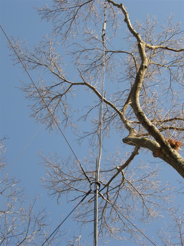
Lower guy connections to shower curtain ring.
The reason for the ring being plastic is if the three trees anchoring the guys should move excessively beyond what the tensioning weight on one of the horizontal ropes can absorb, the ring will release without antenna damage, as the lower guys are directly fastened to the tree trunks without pulleys. There is very little movement of these three trees at the 15 ft level. Note extra rope is left dangling below the sinker for the upper guy, to dampen it from swinging. One main reason the lower guy ring is not attached to the antenna coax and rope passing through it is so any icing on the lower guys doesn't add weight to the antenna.
Tensioning weight, pulley, and 20 oz sinker weight.
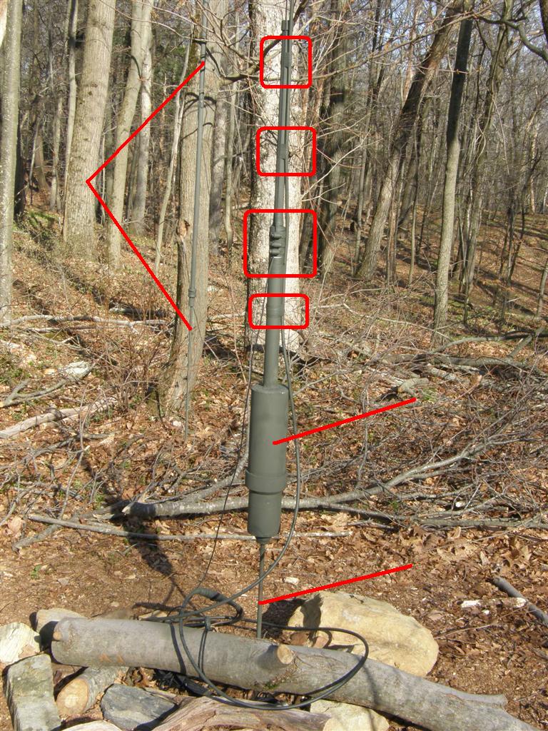
Also for this six-meter antenna, the fastening points for hanging the antenna, and for the PVC rope spacers, are attached to the antenna at low voltage points to prevent detuning in rain or snow.
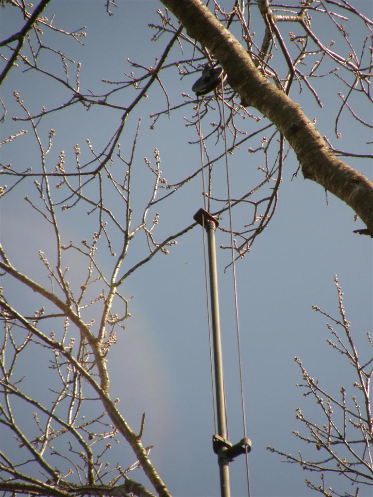
Antenna hung with two ropes to insulated plate three inches above top of antenna. (We used the insulated spacers from a DB-212 side mount dipoles.) The antenna to rope spacers are from two PVC pipe tees joined with 1/2 inch conduit. The rope tees have their tops and bottoms shortened to reduce wind load, so they look more like rings.
A four-inch plastic/composite Everlast clothesline pulley was attached to the tree limb. Because this is a duplexed repeater antenna, all pulleys needed to be plastic, and 3/4-inch PVC electrical conduit separated the steel pipe supporting the concrete-filled PVC water pipe at the base from the ground rod to prevent intermod. If a fiberglass antenna is used, I believe the rope can be directly attached to the fiberglass housing without spacers. Just be certain the fiberglass housing will not pull off the antenna, as happened to a friend's tree suspended vertical. The forces are quite different with top rather than bottom supported antennas, and the antenna might have to be strengthened for top support. For instance, with this antenna, the greatest force is in the middle, just below the phasing coil, but the upper element also needed to be stronger, larger diameter aluminum at the top mounting point, than the original unmodified V6R. Also because of twisting torque in the wind, the 4-1/2 foot radials could not be used, and a coaxial skirt (Kreco) plus 6 mix 31 decoupling ferrites (DX Engineering) were substituted.
Other Considerations:
As Bob, WA1MIK, pointed out to me, our original Heliax coax had to go because it would eventually break with the (sometimes constant) movement of the antenna. Fortunately we discovered a great substitute: ECOFLEX 10+ with only slightly more loss than the Heliax, but has a copper coated stranded aluminum center conductor, bare copper braid, and thick bare copper inner shield. Made in Germany, it's very flexible and light weight. The only problem is the center conductor diameter is too large for regular PL 259 and N connectors, so you need to use their connectors. Any coax with a stranded center conductor and braid should work. A large loop is needed at the antenna base to allow for movement.
The last important point is that the weight of the moveable base needs to be slightly more than the weight of the antenna, coax, and guys including guy weights, because the vertical support rope and coax down lead need to be fastened together at the base, so there is no movement of the tree pulley, or rope over the tree limb, and there is SLIGHT tension on the coax, to reduce movement. Needless to say the antenna, coax, and guys need to be as light as possible, because their weight needs to be doubled, which means double the weight on the tree limb, than would be with just the antenna apparatus alone. This means that if there was no downward support rope, and there was just the antenna support rope attached to the tree limb, there is half the weight on the limb. Problem there is the antenna cannot be lowered for repairs / substitution.
This six-meter antenna was tested in repeater service against a Dominator 5/8-wave chimney-mounted ground plane at almost the same height above average terrain, with radials 15 ft above the roof ridge. The Dominator was unusable because of mixing with devices in the house, but the tree-mounted 5/8 over 5/8 antenna 130 feet from the house exhibited no desense. 100 Watts out of the Dominator has about the same range as 70 Watts out of the tree vertical to a mobile traveling 50 miles away. The results may not be as good on the higher frequencies due to more tree absorption, unless there is a noticeable height increase with the tree antenna.
Credits and Acknowledgements:
I wish to thank Dennis N1MAT, Cliff K1IFF, and especially Bob WA1MIK for their patience in antenna testing and composing this article.
All photos were taken by the author.
Contact Information:
The author can be contacted at: jhaserick84 [ at ] comcast [ dot ] net.
This page was created 18-May-2016.
Go to the top of this page
Go back to Antenna index page
Go back to the Home page
Article text and photos © Copyright 2016 and date of last update by John Haserick W1GPO
This web page, this web site, the information presented in and on its pages and in these modifications and conversions is © Copyrighted 2007 and (date of last update) by Kevin Custer W3KKC and multiple originating authors. All Rights Reserved, including that of paper and web publication elsewhere.