Antenna Index page
Home page
Cavities
By John Portune W6NBC

|
Book Index page Antenna Index page Home page |
Cavity Duplexers Chapter 3 Cavities By John Portune W6NBC |
|
Chapter 3 - Cavities
A duplexer is normally made up of four to six 1/4 wavelength coaxial cavities. Figure 3-1 shows the common configuration. We'll have more to say about the overall structure of a complete duplexer later. First, though, we need to take a look at the important mechanical and electrical properties of the individual cavities.
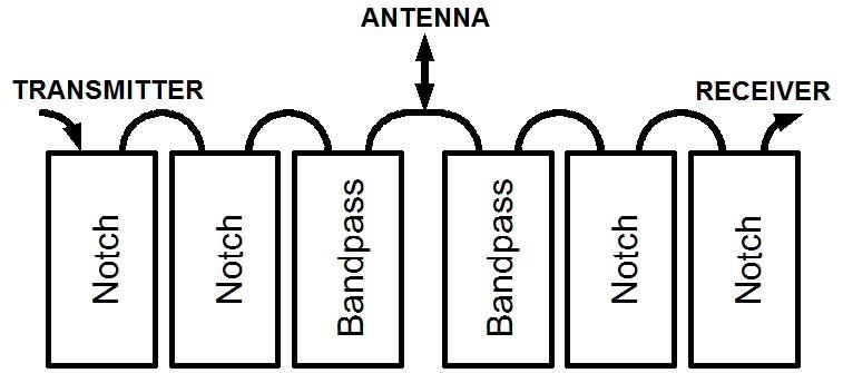
Figure 3-1: Most common duplexer configuration We'll discuss three vital issues: (1) why we use resonant cavities (2) how RF energy gets in and out of a cavity, and (3) the three basic cavity types: bandpass (Bp), band reject (Br) and bandpass-band reject (Bp-Br).
As a final footnote to this chapter, we'll take a very quick look at a cousin of the 1/4 wavelength coaxial cavity, the helical resonator. Especially to hams interested in 6M or 10M repeaters, helical resonators have much practical application.
(1) Why Resonant Cavities:
Here is a very basic question. Why are quarter-wavelength coaxial cavities the only real choice for duplexer filters? It's because there actually isn't much choice. The still continues, even in today's world of miniaturized solid-state electronics, to be the only practical filter type for a duplexer.
The 1/4 wavelength cavity has three essential properties for a duplexer all present in one filter type. The other main types, namely discrete coil-capacitors filters and active filters, lack one or more of the three essentials: (1) the ability to handle power, (2) high Q, and (3) low loss. It is this unique combination of all three in one filter type, that has long made the resonant cavity the only real choice as a duplexer filter. The cavities are not about to disappear from repeater hilltops.
Of these three properties, perhaps the most significant is the first. Only a passive filter, that is, one without active electronic components, can handle the power of the repeater's transmitter. Remember, our sample duplexer must deal with 71 million microvolts (+30 dBm). Active electronic filters can't. Yes, it is true that filters made from discrete coils and capacitors also can handle power, such as in an antenna tuner. But at higher HF and VHF frequencies, and especially at UHF, discrete coil-capacitor filters have poor Q and exhibit high losses. So it is the combination of all the three properties, as found in the resonant cavity, that has caused resonant cavities to be the filer of duplexers for the last fifty years. The principles of this book were just as valid in the 1930's as today.
As an aside, but still on the basic concept of cavities, it's conceptually useful to point out that resonant cavities actually do behave as if they were made up of discrete coils and capacitors even though they aren't. That is, they exhibit real inductance and real capacitance. Hence it is not surprising that the equivalent circuit of the 1/4 wavelength coaxial cavity is a parallel-tuned L-C "tank" circuit. Notice Figure 3-2. Noting this simple fact might make the basic concept of the resonant cavity a little easier to visualize.
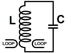
Figure 3-2: Equivalent circuit of a cavity -- parallel L-C tank circuit
Physically though, as opposed to electrically, a cavity resonator is just an open volume of space enclosed by highly-conductive walls. It's metal container "rings" or resonates very readily in the presence of RF energy, very much like a soft drink bottle makes a tone when air is blown across its top. In the cavity, the vibrations aren't in air in thee electro-magnetic field. You can liken a cavity resonator to an organ pipe, a penny whistle or a flute. The math formulas describing both are almost identical.
A hollow metal sphere is technically the best shape for a cavity resonator, at least in terms of electrical efficiency, but it isn't a very practical shape physically. A metal cylinder is much easier. We also add inside In a duplexer cavity there is also a smaller metal cylinder about 1/3 the diameter of the outer cylinder. This is the center conductor. See Figure 3-3. The center conductor is connected to the outer cylinder at one end of the cavity but not at the other.
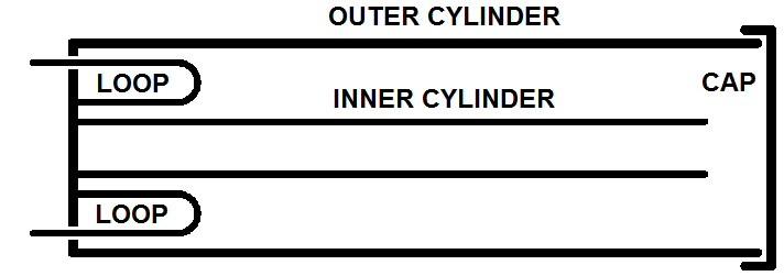
Figure 3-3: Components of a 1/4 wavelength coaxial cavity
You may recognize this configuration as a short length of large-diameter air-insulated coaxial transmission line, shorted at one end. The common duplexer cavity is a simply a 1/4 wavelength shorted coaxial stub. And simply by making it large we easily achieve the three basic desired filter characteristics. In a duplexer, we also cover the open end with a conductive cap placed just a small distance away from the open end of the center conductor. The cover has little effect on the action of the filter. It would work perfectly well as a duplexer filter without the cover, though undesired outside signals could enter.
Field Strength and Orientation:
As we said above, our signal in the cavity is in the form of induce an electro-magnetic (E-H) field. The electric lines of force (E) lie parallel to the length of the cavity, as shown in Figure 3-4. The magnetic force lines lie at right angles, in concentric circles around the center conductor.
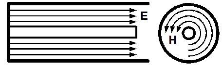
Figure 3-4: Electric and magnetic field orientations
The magnetic field and the associated currents in the cavity walls are strongest at the shorted end of the cavity and weaker at the open end. The electric field and its associated voltages on the cavity walls are just the opposite. They are strongest at the open end and weakest at the shorted end. Both, however, are stronger near the center conductor and weaker near the outer conductor.
These orientation are important when we look at loops and probes for coupling later. It is helpful, therefore, in a solid understanding of duplexers to have a strong mental picture of the E and H fields inside the quarter-wavelength coaxial filters.
Resonant Frequency:
Returning now to the soft drink bottle analogy, if we gently blow across the open end, we produce the bottle's fundamental "note" or frequency. Like our cavity, the soft drink bottle will now be oscillating in 1/4 wavelength mode. If, however, we blow harder, the bottle will break into an overtone mode. The note will now be one or more octaves higher.
These overtone or harmonic modes are why a trumpet, for example, can make many notes with just three valves. For specific notes the musician excites an overtone mode merely by blowing harder. Cavity resonators can also be driven into overtone modes. But here it's a "hazard" not an asset as it is in a trumpet. In duplexer cavities we must avoid overtone modes. They exhibit high losses.
To establish the operating frequency of a coaxial cavity, we merely make the length of the center conductor roughly1/4 wavelength. At 450 MHz, for example, that's about 6 inches. For other bands, the length is directly proportional to wavelength. Hence a 2M cavity's center conductor it is roughly 19-20 inches long, again 1/4 wavelength. On 6M and especially on 10M the cavities become very large. This is where helical resonators, which we'll look at very briefly at the end of this chapter, can be useful.
Perhaps surprising to some, the outer shell of a cavity has virtually no effect on the tuning of a cavity. So we simply make it a little longer than the center conductor. Also, neither does the outer diameter of a cavity alter the frequency. These two facts constitute a key concept. The resonant frequency is determined almost exclusively by the length of the center conductor. This is not however true for all possible resonant-cavity shapes where the resonant frequency is more complex. This is another reason why duplexer cavities are generally 1/4 wavelength coaxial cavities. For other electronic applications the harmonic modes in other cavity shapes are useful.
Outer Cavity Diameter:
Never the less, even though outer conductor diameter has little effect on the resonant frequency, diameter is very important in a cavity. We'll say more about that later. For the moment, merely note that it should not be made larger than roughly 1/3 wavelength. If we do, the cavity will break into a high-loss overtone mode. This means that the diameter limit for 450 MHz cavities is roughly 8 in. A 2M cavity should not be larger than roughly 25 inches. But up to that limit there is considerable benefit in a big diameter. Larger cavities filter better and with less loss. For the home builder, a single large-diameter cavity could work better than two smaller ones. With the construction techniques shown in the previous chapter, large diameters are relatively easy to achieve. So this is an option worth considering for home-brew duplexers.
(2) Coupling Energy in and out:
The next main concept of this chapter has to do with how best to couple RF energy in and out of a cavity. The most common method is a single-turn coupling loop. This isn't the only choice, it is just the most-frequently used method. Actually, there are four practical ways to couple to a cavity: loops, probes, ports and taps. In my investigations I examined each, and the results surprised me somewhat. Let's look quickly at each.
Loop Coupling:
A loop is a simple single-turn coil excited from a connector mounted through the cavity wall. It is most often placed in the shorted end, but may also be put in the side. The far end of the loop is grounded to the cavity. Notice Figure 3-3 again. You may recognize that loops are analogous to the link windings shown in the equivalent circuit, Figure 3-2.
A loop couples to the magnetic field and does this best when it is perpendicular to the H field. Since the H field, as we learned, lies in concentric circles around the center conductor, the loop is normally placed parallel to the length of the cavity and on the cavity's radius. It also couples best where the field is strongest. This, as we also learned, is near the shorted end and near the center conductor. Figure 3-3 shows loops in the maximum coupling position.
In my experimentation I was surprised to discover that the placement of the loops isn't actually critical. Despite what cavity design texts often imply, I have made successful low-loss cavities with loops in the end, on the side and even near the center of the cavity's length. The loop size does change with these position changes, in order to achieve equal performance, but the action of the cavity is much the same no matter where one puts the loops. I will have much more to say about loop placement in a later chapter.
A simple but meaningful analogy to the placement of a loop is pushing a child on a swing. You may push anywhere you like up and down the ropes. If you push at the bottom, you push gently with a long arc. If you push higher up the ropes, you push harder but with a shorter arc. These are equivalent to larger and smaller loops closer or farther from the shorted end of the cavity.
Probe Coupling:
The second, though less frequently used coupling method, is a probe, Figure 3-5. The probe is just one plate of a capacitor used to couple energy in or out. The center conductor of the cavity acts as other half of the coupling capacitor. As opposed to a grounded loop, a probe is open at the end. And as you may have surmised, a probe couples to the electric field (E) instead of the magnetic field (H). But like a loop, a probe couples best when it is perpendicular to the field, in this case the E field, and is placed where the E field is strongest. This, as we've learned, this is at the open end of the center conductor, near to it, as shown.
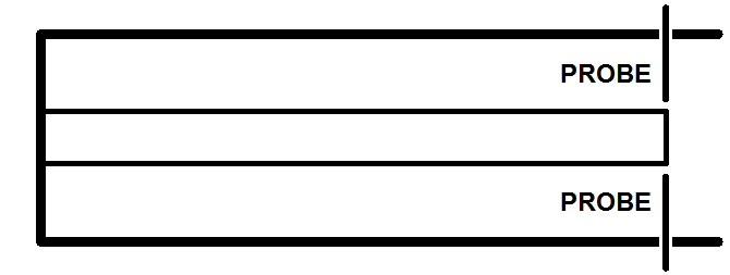
Figure 3-5: Maximum coupling position for probes
In my experiments, I discovered that probes function just as well as loops, and this too surprised me. For it made me wonder why commercial duplexer manufacturers don't commonly use probes. I soon discovered that there is a good reason. In that probes must utilize the E field, they must be placed at the high voltage end of a cavity. A loop, on the other hand, which utilizes the H field is placed at the low voltage end. With probes, therefore, arcing is a potential problem, even at moderate power levels.
Recall as we saw, that a 100 watt transmitter places a 71 volt signal on a 50 Ohm transmission line. But in a good quality cavity Q can easily reach 1000. We therefore multiply the 71 volts by 1000. This makes is clear that very high voltages can exist at the probe end of a cavity.
Port Coupling:
A third way to couple energy, this time normally between adjacent cavities, is to cut a hole in outer walls of both to let some of the field leak through into the adjacent cavity. This is called port coupling. A number of duplexer designs do successfully implement this method. Also the helical resonators, often found in receiver front-ends, commonly use port coupling. It is economical and a space saver. Loops or probes usually need more room.
The main difficulty with port coupling for the home repeater builder is purely mechanical. Varying position and coupling of loops and probes is easy. To change the amount of port coupling one must physically change the size of the port. This precludes easy experimentation. Also, since duplexer filters are often made of cylindrical tubing, a port between cavities is also not easy to fabricate. Small mobile duplexers of rectangular cross section often use port coupling. Therefore, I only mention port coupling in passing. I did not extensively investigate it, though I am confident that the end result would have been the same as for loops or probes.
Tap Coupling:
The final method, illustrated in Figure 3-6, is tap coupling. On the left is an actual cavity with taps.
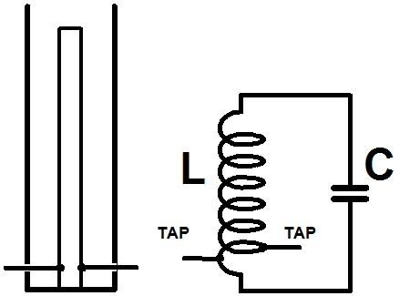
Figure 3-6: Tap coupling and equivalent circuit
On the right is the equivalent LC circuit again with taps. By adjusting the position of the taps, one can achieve a good impedance match as well as efficient coupling. In small cavities, where loops could be too large for the space available, a tap is an easy way to obtain tight coupling.
The disadvantage of tap coupling, however, is isolation. If the type of cavity you wish to use requires two ports, an input and an output tap, isolation between ports is difficult to achieve. Tap coupling finds its best application in single port cavities, such as notch cavities. It is seldom used in band-pass cavities. We will discuss cavity types in a moment.
Which Coupling Type is Best:
Getting practical now, one might ask which coupling method is best? Does one type make a better duplexer? By actual experimentation I found that the answer is no. Surprising as it was for me, all four coupling methods ultimately perform more or less the same after critical adjustment.
Experience, however, did lead me to the practical conclusion that loops are the easiest choice for the home builder. They are also the most common choice for the commercial manufacturers. If a loop will physically fit inside the cavity, you can get it to perform just as well as any other method. It is much easier, however, to mechanically implement and adjust. For this reason, I will stick to loop coupling in the rest of this book.
(3) Cavity Types:
Here is the final main concept of this chapter. It was another surprise to me to discover that all one must do to change the same basic 1/4 wavelength cavity into any of the three basic types commonly found in duplexers: bandpass (Bp), band reject (Br) and bandpass-band reject (Bp-Br) is to reconfigure the loops. Each cavity type has a unique role to play in a duplexer, but the overall physical cavity configuration is very much the same for all.
The best way to grasp how the conversion from one type to another is achieved, is to examine Figure 3-7. It is a classic diagram found in many electronic textbooks. We won't labor over it here, but only point out a couple of important points.
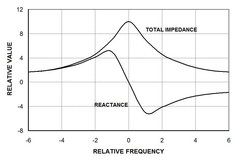
Figure 3-7: Impedance and reactance of an L-C circuit
Bandpass Cavities:
The behavior of a Bp cavity follows the total impedance curve of a parallel L-C circuit, Figure 3-7. The response of a notch cavity follows the reactance curve. To obtain a Bp response we must place the cavity in series with the transmission line. Notice Figure 3-8.
First let's look at a bandpass cavity. When a Bp cavity is off resonance, like a parallel L-C circuit, its total impedance is low. At resonance, impedance reaches a maximum. The absolute value depends on the Q of the cavity.
In a series configuration, all of the energy passes through the cavity. It is coupled into the cavity by one loop and out by the other.
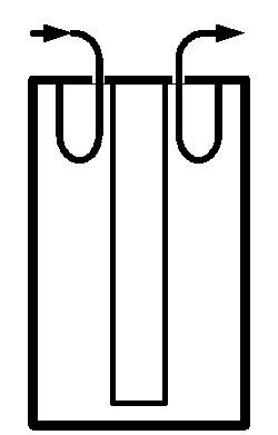
Figure 3-8: Bp cavity, in series with transmission line
At the center frequency, the high Q cavity readily absorbs the energy supplied to it by the input loop. Then at the output loop the H field couples back into the transmission line. At resonance very little signal is lost. To the energy on the transmission line, the cavity is invisible.
But transparency ONLY happens at the cavity's resonant frequency. Off resonance, that is, at a higher or lower frequency, the cavity's impedance rises very rapidly. This greatly suppresses off-frequency signals. Again, in a Bp cavity, non-resonant energy is attenuated in response to the impedance curve of Figure 3-7.
On the other hand, if we place the cavity in parallel with the line, we create a band-reject (Br) or notch cavity or shunt configuration. Figure 3-9 shows the common ways to do this. Parallel or shunt-connected cavities are sometimes called or "suck out" cavities. The difference, therefore, between a Bp and a Br cavity is merely the way the cavity is connected to the transmission line, series or shunt. This alone determines whether it is a bandpass or a notch cavity. Both types still employ 1/4 wavelength shorted transmission line stubs.
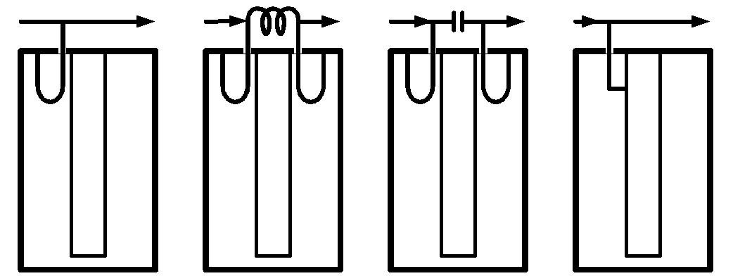
Figure 3-9: Br (notch) cavities, in parallel with transmission line
In (a) a single-loop shunts the cavity across the line. In (b) and (c) the cavity shunts across a coil or capacitor. In (d) a single-tap cavity shunts the transmission line. As we saw earlier, this is generally how tap-coupling is implemented.
Here, however, is the key issue with Bp and Br cavities. A Bp cavity PASSES a small band of frequencies. ALL others are rejected. A Br cavity REJECTS only a small band of frequencies. ALL other pass on through. Said another way, a Br cavity "sucks out" only a small band of frequencies.
In the Br or notch cavity, behavior tracks the reactance curve of Figure 3-7. As you can see, a long way off frequency the cavity reactance is moderate.
As we approach resonance, reactance rises a little but then rapidly becomes a deep notch. By maximizing this response, with either parallel inductance or capacitance, we achieve the familiar response curve of Figure 3-10. Notice that the notch of a Br cavity is very sharp compared to response of a Bp cavity.
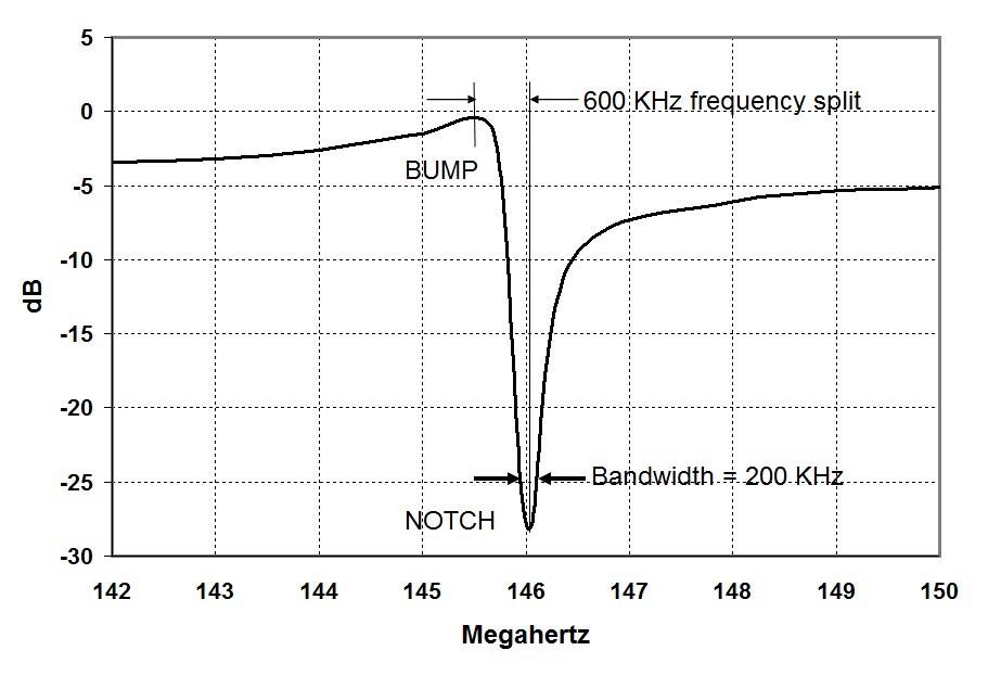
Figure 3-10: Br (notch) cavity response
Bp-Br Cavities:
It is sometimes said that there is a third class of cavities, which supposedly has both Bp and Br characteristics. How is it different? Actually it isn't. All Br cavities have both a reject "notch" and a pass "bump." When the frequency is significantly off resonance the filtering action is only moderate, a few dB. Near resonance one of the reactance excursions produces a small bandpass "bump" which is also only moderate. But the opposite reactance excursion, creates a deep notch. This is the action we are looking for in a Br cavity, capable of many dB of filtering, far more than a Bp cavity. The deep narrow notch is why Br cavities are the real workhorses of cavity duplexers.
In a few designs the bandpass bump is intentionally minimized and the cavity called a pure notch cavity. In theory though, all Br cavities are Bp-Br reject cavities. There is always both a notch and a bump. Hence there really are only two basic cavity configurations, bandpass Bp and band-reject Br.
Bump Up or Down:
Of great importance, however, to duplexer design is whether the bump is configured to be above the notch or below it in frequency. Both are easy to arrange. If the line bypassing the cavity has a shunt inductor, as in b, the notch will be on the high frequency side of resonance. If the line has a shunt capacitor, the notch will be on the low frequency side.
But as I just said, the relationship of the notch to the bump, as compared to the cavity's resonant frequency is very important. And again, that's because the transmit filters must always be one way and the receive filters the other. Which one you will need for your repeater is dictated by the frequency split of your repeater, that is, whether the transmitter is higher or lower in frequency than the receiver. In Figure 3-10, a 2M cavity, the notch is high of the bump. This would be for a repeater with a positive offset of 600 KHz. We'll get to the specifics in a moment.
The Merits of Bp (Bandpass) vs. Br (Notch):
The final piece of basic theory of this chapter will be to compare the basic way we use both types of cavities. For they fulfill different roles in a duplexer.
As far as the bandpass bump part of the response curve of either, both work the same basic way. We want the bump to be centered on the frequency we want to pass on either side of the duplexer. And at that frequency only a fraction of a dB will be lost. The deep notch of the Br cavity(s) is another story, as we shall see.
If bandpass cavities were good enough, that is, if its bandwidth were small enough, then an all-Bp cavity duplexer would be ideal. Unfortunately Bp bandwidth of a Bp cavity is not sufficiently narrow to be the only type of filter used in a practical duplexer. Referring to our sample cavity, its bandwidth is only 3.6 MHz. At the normal frequency offset of a 2M repeater, 600 KHz, it can provide only 3dB of filtering. This is why we must also use notch (Br) cavity cavities in a duplexer. The notches provide many more dB of filtering than the off center rejection of a bandpass cavity.
The notch cavity, however is incapable of rejecting anything but the small band of frequencies on which its notch is centered. But in a duplexer that's precisely what we need. We primarily only need to keep the transmitter frequency out of the receiver. Notch cavities are ideal for this.
On hilltops, however, and to a smaller degree in our own repeater, a combination of both notch and bandpass cavities is necessary. The notch cavities fulfill the duplexer's primary job of isolating a repeater's receiver from its transmitter. The bandpass filters fulfill the secondary responsibility of providing general isolation from the outside world.
Duplexers, therefore, that are used on radios where there are no neighbors, such as in mobile installations if both transmitter need to operate at the same time, a notch-only duplexer can be used. Unwittingly, however, many radio amateurs make the mistake of trying to use this type of duplexer on a hilltop. They are attracted to the small size and low cost of mobile notch-only duplexers. But when they do, they forget that their repeater is wide open to interference from the mixes and intermod that is common at such a site. Small mobile duplexers by themselves are not a good idea on mountaintops.
If economy is imperative, you can us a notch-only mobile duplexer on a hilltop. But you will need to add some outboard bandpass cavities to take care of the neighbors. I have personally built good-performing hilltop duplexers from a low cost mobile duplexer and outboard bandpass "bottles."
Fix in your mind then, that series-connected bandpass cavities are to keep the neighbors out. Shunt connected band-reject cavities are to keep your transmitter out of your receiver. This is a bit of a simplification, for both cavity types do also provide other protections. But in tuning a duplexer to fulfill its main responsibilities you will naturally cover all the bases at the same time.
Helical Resonators:
As we promised, let's take a very quick look at a close relative to the cavity resonator, the helical resonator. You most commonly find them in the front end of narrow-banded receivers. I have experimented with a hybrid form of the helical resonator for ham 6M and 10M repeater application. I personally call a duplexer built from helical resonators a heli-plexer. Here I will only very quickly overview the concept of helical resonators in duplexer service. They do work, though, as my limited experiments have verified.
As we can do with a full-sized antenna, we can also shorten the length of a resonant cavity by inserting a discrete coil into its center conductor or by completely replacing it The quarter wavelength cavity now becomes a semi-helical resonator or full helical resonator. See Figure 3-11. To implement this concept in a duplexer filter one only needs to exert knowledgeable caution. The advantage of semi-helical filters can easily outweigh their small disadvantages. But what are the advantages and disadvantages?
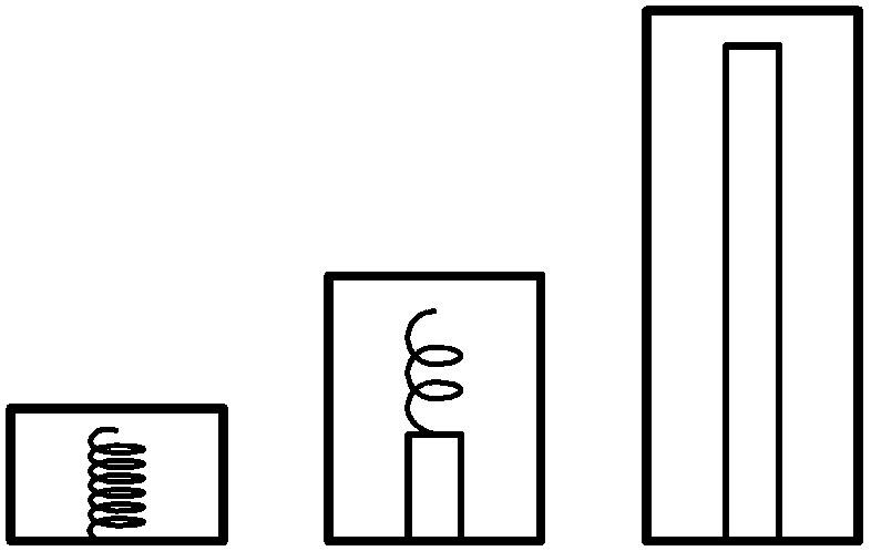
Figure 3-11: Helical resonator, semi-helical resonator, cavity
The main advantage is the large reduction in the length, which on 6M or 10M is highly desirable. However, for exactly the same reasons an antenna shortened with a loading coil has disadvantages over its full-length cousin, so does a semi-helical resonator. Still for 6M and 10M, a shorter filter may well be worth the disadvantages.
Personally I have only just scratched the surface of substituting semi-helical resonators for full-size cavities in repeater duplexers for one working 6M heli-plexer. I have yet to try the technique on 10M. The 6M duplexer was, however, a reasonably good performer. I used 10 in. baking pans for it. So I only offer the following as grounds for experimentation. The 2M cavity in this book should be easy to use as a test bed.
First of all I personally think that one should not reduce the length of the center conductor of a semi-helical filter to more than roughly 1/2 the full-sized length. On 6M that would be just over two feet. Too much coil would be required. And as we have seen, discrete coils exhibit too much loss at VHF and above to be satisfactory as the center conductor. This is why a recommend the semi-helical design, which retains a significant portion of the normal center conductor.
RF skin effect is the major enemy. So make the coil from copper tubing as large as possible and use only a turn or two. This is also a good idea for rigidity. Likewise keep the space between turns wide. To do both of these you will have to retain as much of the normal center conductor as is required to bring the filter to resonance.
I do not know if semi-helical cavities are more or less temperature sensitive than full-sized cavities. I suspect more. So you will need to implement the brass tuning screw technique we saw earlier. It will work much the same. Coupling loops and shunts to create notch cavities should also be similar to full-sized cavities.
I have not seen the semi-helical resonator employed in the commercial two-way radio world. There are two significant reason why. Low-band 30-50 MHz VHF commercial repeaters have not ever been common in the two-radio world. Simplex and remote base radios have rather generally been the rule. Duplexers are not needed for either. Also the widespread use of commercial low-band for land-mobile services is generally fading. Hams are generally the only current uses of repeaters in this spectrum.
One final thought on the practicability of the heli-plexer on 6M and 10M is our old friend band noise. It is three times higher on 6M, and five times higher on 10M, than on 2M. We can live with the lower efficiency of a heli-plexer. The 0.22 microvolt sensitivity of our sample 2M is far more than the noise on the lower bands will ever allow. Less duplexer is needed.
Contact Information:
The author can be contacted at: jportune [ at ] aol [ dot ] com.
Back to the top of the page
Back to Book Index page
Back to Antenna Index page
Back to Home
This article created on Wednesday 09-Jan-2019.
Article text, images and photographs © Copyright 2019 by John Portune W6NBC.
Layout and conversion to HTML © Copyright 2019 by Robert W. Meister WA1MIK.
This web page, this web site, the information presented in and on its pages and in these modifications and conversions is © Copyrighted 1995 and (date of last update) by Kevin Custer W3KKC and multiple originating authors. All Rights Reserved, including that of paper and web publication elsewhere.