|
Back to the Astron index page Back to Home |
Introductory Information on Astron™ power supplies Compiled from a number of different sources by Mike Morris WA6ILQ (See the list at the bottom of this page) |
|
The contents of this page, like most here at www.repeater-builder.com, are totally dependent on donations of information.
If you have a hint or a useful trick please consider writing it up and sending it in.
You probably came to this web page because you have an Astron supply that has problems. On this web page we present some cautions, solutions, modifications, repair and rebuild tips.
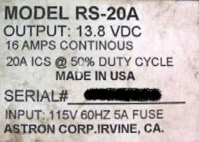
The above model tag shows that an RS‑20 is rated by Astron at 16 amps continuous duty. Don't believe it !!! My personal opinion, which a number of my repeater-building friends share, is that you never load an Astron at over one-half it's advertised rating, and most folks I know use 40% as a starting point. In other words, an RS‑50 is only good for about 20 to 25 amps in continuous service. Astron advertises their supplies with peak duty amperage numbers and the ICS on the label DOES NOT stand for "Intermittent Commercial Service" (a description that has a standard meaning), instead it stands for "Intermittent Communications Service" (Astron's own invention). Astron marketing explains that by saying that in normal operation the user listens (i.e. low current) a lot more than he / she talks (high current). They say this gives time for the heat sink (and pass transistors), transformer, etc. to cool down. In other words, they are marketing peak intermittent current capacity and counting on a low duty cycle for their product to survive everyday use. Due to the fact that Astron products have repeatedly failed a number of system owners have abandoned Astron as the primary supplier their repeater power supplies.
The linear Astron supplies are based on the common "723" series regulator chip (originally designed and sold by Fairchild Semiconductor in the 1970s as the µa723). The basic Astron linear supply design is straight out of the data sheet and application notes. At least six different manufacturers second-source the 723 chip. I've seen Astrons with the National Semiconductor LM723 chip, the Motorola MC1723CP, and both the Signetics and Texas instruments version. In the Motorola Semiconductor model number structure, the CP indicated commercial temperature range and a plastic package (as opposed to military and ceramic), but it's the same thing as a 723C. For simplicity in this writeup I'm going to use just the LM723 number no matter what manufacturer made the chip you have in your particular Astron. Most of the chip reference web sites have the data sheet and applications notes, and the theory and design information you will find there is as true today as it was when the chip was introduced... Starting with the design notes is a good idea. There is a downloadable copy of the data sheet and an application note later on on this web page, plus PDFs of a few magazine articles.
Note that the common LM723 chip used by Astron is temperature derated - the performance is only guaranteed over a 0°C to +70°C temperature range (the so-called "commercial temperature range"), instead of -55°C to +125°C (the "military temperature range"). If your Astron is going to a mountaintop repeater site that gets cold in the winter I'd replace the chip with one that is guaranteed below 32°F / 0°C... In every Astron I've been inside the chip is in a socket... Yes, -60°F / -55°C is overkill for the average repeater, but your only choices are "Commercial" with a 0°C rating, or "Military" with a -55°C rating. Given that situation, ordering a mil-spec chip is the simplest way to get one that is rated below freezing... and you can use the original 723 that you removed from your supply somewhere else.
Before you start debugging your Astron, I suggest that you read the first three articles in the "Linear Power Supply Design and Theory" section below.
The common Astron linear supply is not a finished and reliable design, as this email from Skipp May WV6F indicates:
Many early Astron supply regulator boards are problematic.
The 723 regulator chip is often placed in under engineered circuits. There are on-chip amplifiers with an incredible amount of gain. Said amps with a lot of open (and closed) loop gain makes a nice RF sniffer when the designer forgets to properly bypass various sections of the regulator circuit. Plus there is poor response to high frequency glitches and noise. Proper 723 pre-regulation is another common circuit shortfall. The end result is often seen as erratic operation, false crowbar circuit firing and regulator chip failure. The crowbar circuit itself works well when triggered. Most of the crowbar problems I've seen (once you get past the Astron regulator board) were traced to older filter capacitors under relatively heavy loads.Many Astron power supplies work well for decades, a lot of the problems surface when feeding higher impedance and reactive loads. The load impedance and current demand presented to the supply can be a big factor in the performace and reliability of the power supply.
The 723 regulator chip is an excellent building block, but making one play well with multiple nearby 50kw (or higher) broadcast transmitters can be a test of ones engineering skills. Fortunately, the data sheet has all the required information. Much of the mentioned data sheet information is often overlooked. Problems resulting from poor 723 regulation circuit design shortcuts often rear their ugly head at much later dates.
The Astron circuit design engineer is certainly not the first, nor the last person to misunderstand or overlook certain characteristics of the LM‑723 regulator chip. I've found very few LM‑723 regulator circuit designs done really well.
There is more from Skipp's email further down on this page.
One of the overlooked items is the compensation capacitor value - as this web page by Dr. Paul Webster VK2BZC elucidates: Power supply design with the LM723. The average Astron has NO compensation cap at all (leaving out that cap is one of the cost-cutting methods the Astron designer used). The 723 data sheet (which you can click on below) has a number of sample circuits, and some show no capacitor, some show 15pF, some show 100pF, the largest is 500pF. Some design notes rate the capacitors in NanoFarads (1,000pf=1nf). If your supply has a compensation cap you will find it connected from pin 4 to pin 13 on the DIP package (common), or from pin 9 to pin 2 on the TO‑5 round metal can (rare). If your supply does NOT have a cap from pin 4 to pin 13, ADD ONE - a 470pf or 500pf tacked across the back of the IC socket is all that is needed. By the way, the "this country" that Paul refers to on his web page is Australia.
That said, if your Astron is going into current limit at random times, this comment from an email sent by Ron Rogers WW8RR is relevant:
A VERY common cause of random current limit shutdown in linear Astron supplies is due to the manufacturing process: a bad solder joint on the collector tab of one of the pass transistors. During manufacture they solder the buss wire from collector to collector. If you take a pair of pliers and grab the buss wire next to the solder joint at each transistor and pull on it, you will most likely find one that will simply pull off.
All it takes is for one of those transistors all wired in parallel to have a bad collector‑to‑buss solder joint and all of the source current from the supply tries to flow through the Emitter-Base junction of that one transistor that has the bad solder joint. Bingo !!! Immediate current limit mode !!
From yet another email to repeater-builder:
Another common failure (these supplies are full of them) is due to the use of parallel‑wired diode bridge rectifiers. A good example is on the RS‑35 supply schematics. They use two packaged bridge rectifiers that are wired in parallel with pieces of #10 wire tying them together with no attempt at current equalization. To use a Martha Stewart term, this is A Bad Thing, engineering-wise; at least the designer used current balancing resistors on the pass transistors. Only the positive halves of the bridge rectifiers are used; the negative ends are left floating. Unless the two bridges are absolutely identical, or at lease very closely balanced, one will hog most/all of the current and the other will just sit there and watch. Eventually one diode will short or open, and that often takes the other one along with it. This causes the supply's primary fuse to blow. If your supply instantly blows the primary fuse, unsolder the two heavy transformer wires (frequently colored yellow) from the bridge rectifier terminals and then see if a new fuse blows. If not, check for a shorted main filter capacitor and shorted pass transistors. If all checks out OK, chances are high that one or more diodes have shorted. They have to be completely unwired to be properly checked. I bought several 1,000V 50 Amp diode bridges for about US$5 each as replacements and just use one of those in place of the two parts in parallel in RS‑35s. The ones I have here are labeled KEST KBPC 5010 or KEST KBPC‑5010 and are still being sold on eBay as of this writing (October 2007). Click here for the KBPC-5010 data sheet.
Here's a photo of the inside of a dual-rectifier Astron RS‑35.
Here's a photo of the 50 amp replacement. It's the same physical size as one of the existing rectifiers.Both photos above taken by WA1MIK to illustrate the above situation.
Astron used different transistors at different times in their history. Don't be surprised if the ones in your supply are not listed in the table below (and if they are not, please let us know what you find). Just Google the part number and you will find the info somewhere on the web.
From an email to repeater-builder from an amateur that works in the power supply design field...
Another fault in the Astron is that they under-engineered the crowbar circuit - they used a design appropriate for a 7 amp or 12 amp supply in every size supply up to and including 50 amps !!! The active part is a 2N681 that is rated at 25 amps peak. They later went to an S0565J device, but that is rated at only 50 amps, 65 amps or 70 amps (it depends on which manufacturers data sheet you read)... and on a crowbar you ALWAYS go for at least two times the maximum current expected, if not four or even ten. After all, the crowbar is supposed to trigger when the regulator failes (or when the output voltage somehow exceeds the crowbar trip voltage), and the purpose of any crowbar circuit is to blow the main fuse and shut down the supply. To do that the SCR has to simultaneously short the full load current of the supply PLUS dump all of the stored energy contained in the fully charged filter caps, and do it without comitting suicide by overcurrent ! Using an undersized SCR or small diameter (i.e. current limiting) wiring is defeating your own purpose. Personally I'd use a heftier crowbar device and bigger internal wire if I was repairing or rebuilding a high-current Astron.Note from Mike WA6ILQ (who got it from Chris KL7DM):
For those that want details, here you are:
Note 1: The maximum collector current specified above is only valid as long as the internal transistor temperature is less than the rated maximum temperature. Also note that the higher-numbered 2N3773 has a max current of about 1/2 that of the lower-numbered 2N3771.
Transistor
Part
NumberIC
Collector
Amps
(see note 1)BVCEO
Breakdown
VoltagehFE
Gain
min‑max
at ICPD
Power Dissipation
in wattsDigiKey Price
each
(mid 2006)2N3055 10 60 20-70 @ 4a 75 $2 2N3771
ECG-18130 40 15-60 @ 15a 150 $2.50 2N3772 20 60 15 @ 10a 150 $2.10 2N3773 16 140 50-60 @ 8a 150 $2.25 2N5301 30 40 15-60 @ 15a 200 $4 2N5302 30 60 15-60 @ 15a 200 $4 2N5686 50 80 15-60 @ 25a 300 $8
All the devices listed in the table above are drop‑in replacements with better performance for a very reasonable price.
One of the two pass transistors on the heat sink of an RS‑20.
The "9549" is a date code and indicates that the
transistor was made in the 49th week of 1995.Back to the email:
The "book" rated dissipation of a power transistor is noted in the book as having been measured at at 25°C (77° F). As the temperature goes up, the power dissipation ability goes down. During long heavy load situations (like a long repeater transmitter key-down session) the internal chip temperature of the pass transistors will be a lot hotter than the case, which will be hotter than the heat sink. The characteristic that causes a time lag between internal chip temperature rising and the heat sink temperature rising is called thermal resistance. Think of the situation as including a "heat pipe" between the source (the transistors) and the destination (the heat sink) - like water, the larger the diameter of the pipe, the greater the quantity flowing, and the lower the thermal resistance, the faster the transistor can dump the heat into the heat sink. You can't do anything about the thermal resistance between the internal chip and the case of the power transistor (i.e. the internal construction of the power transistor), but you can lower the thermal resistance between the transistor case and the heat sink with an application of the proper type and amount of heat sink compound. And you can add a fan blowing air across the heat sink to help it shed the heat. Note that due to the density of the air a fan on a heat sink at a mountaintop site at 5,000 feet won't cool as well as the same fan on the same heat sink at sea level, fortunately mountaintop sites are generally cooler than at sea level.The 2N3055s, 2N3771s and 2N3772s have been found in known-stock Astrons (the 2N3055 is found only in the earliest units and Astron switched completely to the 2N3771 at some point). The 2N3773s, 2N5301s, 2N5302s and ECG181s have been found in used ones bought at swap meets. The 2N3773s may have been stock (if they were replacements they were very nicely done, and I couldn't tell), the 2N5301s and 2N5302s were obvious field replacements.
I use the 2N5686 exclusively as a replacement in large supplies as not one supply I have rebuilt with them (over 20) has EVER come back to haunt me (at least for a pass transistor problem). Yes, in some cases they are overkill and they do cost more, but the price difference on four new devices for an RS‑35 is around $25, even if the originals are 2N3055s or 2N3773s. If you find 2N3055s in your used supply and don't want to go to 2N5686s at least replace them with 2N3773s, and preferrably 2N3771s. The 3773s provides 60% more current capacity and twice the power dissipation for an additional 25 cents each. If you use 2N3771s that's triple the current for an additional 50 cents each (and that's what Astron uses anyway).
And think about it: If you go cheap what is a future power supply failure, the down time, a round trip to the repeater site (don't forget to consider the price of vehicle wear and tear plus the gasoline) and ANOTHER power supply rebuild going to cost? What is your time worth?
Note from Mike WA6ILQ: I read an article in the local newspaper in 2008 that was discussing the cost of the daily commute to work. The author was driving just under 10 miles per day as his round trip. He totaled up gasoline, maintenance, insurance, and figured a 10-year depreciation on the difference between the price of the new vehicle and what he could get for it 10 years later. His total came out to right around 45 cents per mile. As an aside, the IRS allowed 50.5 cents per mile for business use of a personally owned vehicle in early 2008). It's probably higher now.
Back to the email:
Don't mix the transistor types !!! The emitter ballast resistors do their balancing act only when the transistors are identical. Always replace a dead pass transistor with an identical part number, or if you can't find an exact match, then replace all of them as a group. And don't go down in ratings - if you find 2N3771s do not replace them with 2N3055s, 2N3772s or 2N3773s. A short rule of thumb: Use only the 2N3771s or 2N5686s - and use all of one or the other.
If you have to replace all of the pass transistors in a supply, and if the old ones are 2N3055s or 2N3773s do yourself a favor and buy something larger ‑ at least 2N3771s (also known as the ECG181) and preferably 2N5686s. Note that you can probably use fewer 2N5686 devices than the 2N3771s that came with the supply.
Note from Mike WA6ILQ:
Note that on some models it may not be worth the upgrade parts
or the effort to install them . The RS‑7 uses a
single 2N3771, a 30 amp device. The RS‑12 uses
(used?) a pair of 2N3771s (the dual transisitors are obviously
a holdover from the days of 2N3055 pass transistors as each one
was only good for 10 amps)... so the stock RS‑12 has 60 amps
worth of pass transistors for a supply rated for 12 amps... On
the RS‑7 and RS‑12 (and similar low current supplies),
at least, save your modification time and money.
Back to the email:
If you find one bad pass transistor measure the resistance of all of the emitter ballast resistors (the current balancing resistors) and compare each against the others. If even one is different, replace ALL of them with new 5% (or better) units - that way you have identical values (after all, they are supposed to evenly distribute or balance the current, and can't if they are not absolutely identical in resistance). Using all new from the same batch is the simplest practical way to get identical values.Don't forget to use some good beryllium based thermal compound (the thick white stuff that is the consistency of axle grease), but don't go overboard - you want just enough to put a thin layer between the transistor and the insulator, and again between the insulator and the heat sink. All you are doing is eliminating any air pockets. Note that beryllium compounds are known to be human carcinogens when inhaled, fortunately the greasy consistency of the heat sink compound prevents any airborne dust, but you still want to keep it off your skin (i.e. use a surgical glove or gloves for protection, and maybe a popsicle stick to spread it thin). You can usually beg a pair or two of rubber or nitrile gloves from paramedica, ambulance attendants, auto mechanics, nurses, doctors or vetrenarians. See this web page for more details on beryllium. See This page also. See this Wikipeida page on the results.
If you can't find the beryllium based thick white stuff then use the Arctic Silver that is made for use between the CPU chips and the heat sinks in high-end PCs.
As long as I am inside the Astron I also do the following:
Note from Mike WA6ILQ: See the WB6FLY note further down this page on this topic.
- Some Astron models use stud mount rectifier diodes, others use one or two rectifier blocks in parallel. The ones that use dual rectifier blocks get them replaced with one large one rated at least 2 times the maximum current of the supply, if not 3 or 4 times. Yes, I prefer to use a 50 amp bridge in a 12 amp supply. It's cheap and I won't have to worry about it ever again. Some of the larger supplies that use a pair of rectifier blocks get converted to 75 amp or 100 amp stud‑mount diodes. Astron uses two 40 amp diodes in parallel on each side of the transformer in an RS‑70, personally I feel that's not enough headroom, and besides, there aren't any current balancing components on the diode pairs. In the last one I rebuilt I used two 200 amp diodes, and because I used one on each side of the transformer there was no balancing required.
- I add a 0.1 uf capacitor rated at 100 volts (or better) from the positive terminal of the large bridge rectifier to ground.
- I add three 0.01µf 600 volt (or better) bypass caps - one across the AC line and one more from each side of the AC line to ground, and I use the gap-cap version of the bypass cap if I can have them in stock (see http://www.vishay.com/docs/28521/gapkap.pdf). If you are going to google it then note that Vishay calls it a "gap-kap". Vendor pointers for the Vishay 0.01µf S103M69Z5U283L0R are here: Digikey and Mouser (and note that the photo in the Mouser web page is of the non-gap-kap version). I've found a single cheap ceramic bypass cap across the line in some of the Astrons I've worked on, most don't have it. And since the Astron is on my bench because it has problems, I assume the existing bypass cap is damaged and it gets trashed.
- I add three 150 volt Metal-Oxide Varistors (MOVs) - one in parallel with each of the gap-caps mentioned above (areas with 220 / 240 volt AC mains will need higher voltage devices). Some Astrons already have one MOV (across the power line) already in place. Due to the normal failure mode of a varistor (see the "Regarding MOVs" paragraph below), and due to the reason that the Astron is on my bench is because it has problems, I assume the existing varistor(s) is (are) toasted and trash it (them). See the MOV note below for the preferred part number.
- I add the missing compensation capacitor (470 pf or 500 pf) - see the 723 data sheet and the text above.
- I test the connection from the chassis to the ground prong of the power plug. Use your ohm meter on the X1 scale to test between the case to the ground of the AC mains power plug (the round prong in the USA). It should show zero ohms. I've worked on several Astrons that arrived with a non-functional safety ground wire in the power cord. I scrape away the paint and add a star washer under the power cord green wire lug. On one I found the ground lug crimped onto an insulated wire (i.e. they hadn't stripped the wire before they crimped the lug onto it). In each case the housing / chassis was floating above mains power safety ground. Remember the power plug ground wire is a SAFETY ground, and your survivors will appreciate it if you don't scrimp on the safety. Make it a good solid ground. And remember that the "green" wire in the power cord may be green with a yellow stripe or stripes.
- Some Astrons have the negative side of the DC output grounded to the case, some don't. You want the negative side floating. Again, use your ohm meter to test between the negative terminal to the ground (round prong) of the AC power plug.
I add more split or star washers under the pass transistor mounting screws. I've seen thermal cycling loosen them. As long as you are inside the housing I would add split washers under the filter capacitor screw heads as well. In several cases I've found multiple filter capacitor connection screws only finger tight.
Most of the time I relocate the voltage adjustment pot to the front panel, mounted under the voltmeter (if present). In most Astron supplies the voltage adjustment is a 1K carbon linear pot. I simply mount a screwdriver-adjust pot (of the type that has a locking nut on the adjustment), and run wires to the pads where the regulator board voltage pot used to be. I use a three conductor shielded wire for this (that's three wires plus the shield), and ground the board end of the shield. By the way, the vertical tab on the left side of the pot in the photo is an anti-rotation feature - it prevents the pot from rotating in the front panel. When you mount that style of pot you need to drill two holes - a large one for the center shaft and a second one just large enough to clear the anti-rotation tab. And sometimes the anti-rotation tab is taller than the front panel is thick, you may have to shorten it a little (a pair of diagonal cutters and a flat file to take the burrs off works just fine for this).
On the VS series, and on the supplies where I relocate the voltage adjust pot to the front panel I add a ferrite bead to each lead of the front panel potentiometer(s) right at the PC board (but not on the shield). If necessary a drop of hot melt glue holds the bead in place. Some of my Astrons are at broadcast sites, and I don't need high RF levels confusing the voltage regulators, the overcurrent foldback circuit, or the crowbar circuit.
I add an IEC style power cord fitting (available for free from a dead PC power supply). Yes, it requires a bit of sheet metal work, but it's worth it to prevent tripping over a dangling power cord again. I still have scars from the rough concrete on the steps of the repeater building. The IEC may not be appropriate for the high current units (i.e. an RS‑50 or RS‑75) unless you can find a high current IEC and a #14 or #12 wire IEC power cord... the last thing you want is for someone to slip up and use a leftover wimpy #20 or #18 cord originally made for someone's PC monitor. And label the power supply end of the #12 cord as being for the Astron - you don't want some newbie who is helping out on a repeater site visit and has his head in the back of the rack accidentally swapping the Astron #12 cord with the #18 cord that belongs on the link radio power supply.
If you do chose to add an IEC power connector you need to make sure that the current rating of the IEC connector is at least twice the measured AC current draw of the supply at max DC load. Then you get to make sure that it is wired properly - see this drawing. Some IEC connectors have color dots on the pins: brown is the international standard for hot, blue for neutral, and green or yellow for ground. Some manufacturers use molded-in lettering, "L" for line, "N" for neutral, "G" or "E" for ground or earth. Some even use both the molded letters and the color dots.
A lot of Astrons have the incoming power hot lead feed the fuse holder, then the front panel power switch then the load (the transformer primary). Some have the hot lead feed the switch, then the fuse holder then the load. The second wiring method is preferred. Make sure the fuse holder is wired properly - the center pin is supposed to be fed by the hot lead (unswitched) and the outer sleeve of the fuse holder (nearest the case) goes to the switch and then to the transformer primary. This is another life safety issue where your survivors will thank you. The idea is that as you remove the fuse from the holder the source (the center pin) connection is broken first, and everything in the box is electrically dead.
In other words, the sequence of flow for the power should be from the hot wire in the power cord (or the hot pin of the IEC power connector) to the tip of the fuse holder, and from the barrel of the fuse holder to one side of the AC power switch, then from the other side of the switch to the power transformer primary. The other side of the power transformer should go to the neutral wire in the power cord (or to the neutral pin of the IEC connector).
Most of the Astrons use a rocker-style power switch with an internal neon lamp to indicate when the power is on. After a while the neon lamp dies from old age. I add a diffused (for wide viewing angle) bright green LED to the front panel, with an appropriate series resistor, and wired across the +12vDC output. Or you can do as one friend did and carefully take apart the switch and replace the dead neon lamp with a bright red diffused LED, then reassemble it. Add the appropriate series resistor and you are done. Regarding MOVs, remember that they have a finite life and do wear out. This is because when the voltage across a MOV reaches the breakover point, the MOV avalanches and conducts therby shorting the excess impulse energy into heat within the body of the MOV itself. If it draws enough current the MOV just blows the input fuse in the device. If a MOV absorbs a spike too big to digest they just short out. In that situation the shorted MOV just blows the new fuse as soon as you replace it.
As I said above, if the spike is not very energetic the MOV just dissipates it as heat. The problem is, if the MOV gets hot enough, the internal heat affects the MOVs internal characteristics - its breakover voltage (threshold voltage) increases with each hit it takes. The next impulse comes along and less of it gets shunted. If a MOV sees enough action, the threshold voltage goes up to where it is effectively an open circuit. As you would expect, when the MOV is effectively open the equipment protection is compromised to zero and you won't know it, but physically the MOV still looks perfectly good.
This failure mode is why the common PC "surge protection" power strips are a joke and a delusion - usually all that is inside is a single unlabeled, bottom-of-the-quality-barrel MOV (it may not even be the right MOV, in multiple cases I've found a 250v MOV in a low-end Chinese made "surge protected" 120v power strip). Tripp-Lite "Isobars" are much better - and I use one as the rack cabinet power entry protection at every repeater site. MOVs are cheap, however, and if they re the correct voltage are better than no protection at all. Just make them your secondary layer of protection, and plan on replacing all three of the MOVs every so often, especially if the power line feeding the power supply has taken a lightning strike (at which point you replace all three, plus the gap-caps and then go looking for further damage).
The other common MOV failure mode is where the MOV just plain shorts out and vaporizes the fuse and frequently itself. I've seen MOVs reduced to two bare leads waving in the breeze and bits of red plastic scattered around the inside of the power supply case. But the supply was repairable, and went back into service, and 8 years later (as of mid-2010) is still in service.
When you purchase new MOVs you need to make sure that you pick the voltage properly. A MOV rated at 130 VAC is suitable for a 120 VAC circuit only if its tolerance is tight, say plus or minus 2%. You won't find that tolerance or quality at Radio Shack (their part 276-568, and the last time I checked they were over for $2 each). If your line voltage is a little high then it may be a good idea to install new MOVs rated at 140 VAC with a 10% tolerance. Mouser (and others) stock them. I use the Littlefuse V130LA20A, which is available from Mouser for under $.50/each (2009 price).
You would think that installtion of the MOVs and gap-caps could be as simple as soldering them right to the pins on the back of the IEC socket that you installed in the back of the case, and yes, you can do that. Rather than unsolder and solder replacements on a supply that is headed for a hilltop, it might be a better idea to connect them via a multi position screw terminal block bolted to the inside of the cabinet just above the IEC socket. By the way, the dead-short failure mode of the MOVs generates a LOT of heat, so mount that terminal block where a long burst of heat that is much hotter than a soldering iron isn't going to destroy a expensive part - like the 100,000 µF filter cap in an RS-50.
As an aside, this failure mode inside a plastic cased low end "surge arrest" or "surge protect" power strip in an invitation to a major fire - especially if that power strip is sitting on a flammable surface, like on a carpeted or wooden floor in a residence. Don't forget that most plastics are petroleum based and are a very flammable fuel when melted (like from heat).
Note from Mike WA6ILQ:
One of the RS-20 Astrons that I own was purchased at a ham swap meet simply
becasue it was tagged with a simple note in big block letters on a 3x5 inch
file card... "NFG, blows fuses". I paid $5 for it, took it home, popped
the cover off, poked around with a VOM for 5 minutes, cut out the the old
MOV with some side cutters and put in a new fuse. The supply worked
just fine. I did most of the critical mods listed on this page (add 1 new
compensation cap, one new .01 uf cap from the positive side of the rectifier to
the negative side, 3 new V130LA20A MOVs, 3 new Vishay gap caps, floated
the negative side, verified the chassis ground (the green / 3rd wire in
the power cord), added split washers under the pass transistor mounting screws
and under the filter capacitor screw heads, added a wide diffused and obnoxiously
bright green LED to the 12 volt output, etc.) and the unit is now the primary
supply for a set of base station radios at a Red Cross chapter building.
If the Astron I'm rebuilding is going to be powering a continuous duty load (i.e. at a repeater site) I add a voltmeter, an ammeter, and if it's a high duty cycle load (i.e. a busy repeater) a 24vDC fan (or two 12vDC fans in series) blowing air across the heat sink... If it's a busy repeater with large supply (with a wide heat sink) I'll use definitely use two. A 24vDC fan run at 12vDC moves enough air to keep the supply heat sink cool and will last a lot longer than a 12v fan running at normal speed. To save the fans from running 24x7 you could use a simple SPST snap-action thermostatic switch mounted on the heat sink. Just drill two small holes in a flat area of one of the heatsink fins, and mount the switch with a dab of thermal contact grease to ensure a good heat transfer. Another option to switch the power to the fan(s) is a PTT-triggered timer so that the fans run only when the repeater is actually in use. Many repeater controllers have digital outputs that can be used to control other things, including a fan or a set of fans. If your controller does, and the programming supports it, you could have it ignore a kerchunk (i.e. a transmission of less than 30 seconds), yet turn othe fan(s) on when the repeater becomes active (perhaps more than 60 seconds). If your repeater controller has analog inputs and allows you to measure temperatures and allows you to take action based on them then you can measure the transmitter heat sink and the power supply heat sink, then control the fans based on that.
Note from Eric Lemmon WB6FLY:
One good choice of snap action switch is the Cantherm Corp. #R2005015
normally-open thermostat that closes at 50 degrees C (about
122 degrees F). When attached to a heat-sink fin, it
turns the fan on when necessary, and keeps it on until the heat sink
cools below about 100 degrees F (right around body temperature). This
particular switch is available from Digi-Key as Catalog Number 317-1094-ND,
for about $9 each (2005 price).
(end of the power supply design email)Don't forget that the power transformer and rectifier block need cooling as well. Depending on the duty cycle you may want to add an additional fan blowing air through the Astron housing. Note that the bridge rectifier is going to drop about 0.7v to 0.8v at anything up to the full load current. Let's say that you have an RS‑50 loaded to 50% current. 25 amps times 0.7 volts is 17.5 watts, and that's only at half of the maximum current. 17 watts is a LOT of heat for a small-package bridge rectifier to dissipate, especially with nothing but convection cooling inside a sealed metal case. As easy as it is to do, add a little dab of white beryllium thermal grease under the rectifier block and let the bottom plate of the supply shed some of the heat, or remove the epoxy case unit and install a couple of heavy duty stud-mount diodes into the backside of the heat sink.
The power transformer itself is not 100 per cent efficient so it will generate some heat as well. If the outer case of the supply is so hot that you can't put place the palm of your hand on it full time then it's worth punching a 3 inch or 4 inch diameter hole in the top and bottom of the power supply case, put copper screening over the holes and use a 24v fan to force some air flow over the internal components (punching one of the holes in one side of the lid and the other in the other side of the bottom results in cross-wise air flow at zero cost). If cabinet clearances are tight (i.e. no room above or below, like in most rack mounted repeater systems), I'll punch both ends of the Astron cabinet, add the copper screening and mount the internal fan on the outside over the intake hole (in general, pushing air into a cabinet cools better than sucking air out). Don't forget a finger guard of some form.
Four notes from Mike WA6ILQ:
1) Copper screening is stocked by many model airplane / hobby
stores and you will find that it is easy to solder a grounding pigtail
to it. Copper screening is very soft, be gentle with it. If
you can't find it locally then check the
Georgia Copper web site. They sell
"copper mesh" in 12
inch by 12 inch squares - but the minimum shipping cost is enough that you
will want to pool an order from several people and / or several
projects.
2) A constantly-operating fan pulls a lot of dust and dirt into the
equipment. Besides, the fan is ineffective until the device(s) get(s)
warm, so starting it immediately upon key-up is a waste. In my opinion,
a snap-action thermal switch mounted on a heat-sink fin is the simplest
and most practical means of controlling a fan. If you are going to mount
a fan to blow air through the case then you are probably also adding a fan
to blow air across the power supply heat sink. Just wire the fans together.
3) If you are going to add a fan (or two) to a repeater site power supply (actually,
any device) make sure you use a new name-brand ball bearing fan - cheap fans use
brass or bronze bushings, cheaper fans use plastic bushings, good fans use ball
bearings and are worth the extra money - what is a service call to replace a fan
going to cost you? Fans with cylindrical or tapered needle bearings are even
better (i.e. mil-spec quality) but not too common and when they are found are
usually expensive.
4) Don't buy surplus fans for a repeater site. Bite the bullet and buy
new quality ball bearing fans. I don't need to make yet another hill
trip to replace a used fan. I've seen surplus fans advertised as "new
old stock" where the bearing cap has been removed, fresh grease added, and then
replaced. No, thank you.
Item numbers 6, 7, 8, 12 and 13 in the list above can be done at almost zero cost. Adding a dab of heat sink compound under the rectifier block(s) is almost free as well. Adding the compensation cap in item 5 is mandatory for repeater sites or client sites, and optional for the workbench.
Note that on some of the Astrons the DC output is floating from the case and on others the negative output is connected to the case. A good example of this is to look at the RS‑35 schematics from 1987 and compare them to those from 1991. Personally, any supply that is not owned by me and goes across my bench gets a P-Touch label stating either "Negative side is floating from the case" or "Negative side is grounded to the case". And Astron isn't consistent - some are grounded, some are floating, and some are in between - the Astron RS-50 / RM-50 schematic that is dated March 1996 shows a 3K resistor from negative to chassis. The RM-50 schematic that is dated January 2000 shows a hard ground. I've had an RM-50 on my bench that had the negative side floating, and I know the history of that supply - I can state that is how it came from the factory. My personally owned supplies all have the negative side floating.
Eric Lemmon WB6FLY ran into this situation and wrote about it on the reepater-builder yahoogroup:
It has come to my attention that Astron has a built-in design flaw that may cause problems for some repeater operators.Note that some Astrons have a resistor from negative to case, so the measurment that Eric refers to may not be a short... it may be a value in the range of a few K ohms.
I discovered this when I replaced a suspect Pyramid power supply at my mountaintop 220 MHz repeater with an Astron SS-12 switching power supply. When I got back home, and in a very quiet environment, I was shocked to hear a very prominent 60 Hz hum on the 220 carrier. Since this switching power supply uses a switching frequency up in the 40 kHz range, I could not understand how there could be 60 Hz hum!
The very next day, I took a known-good DuraComm switching power supply with me and returned to the repeater site and exchanged the two units. This time, I moved some distance away from the repeater building and tested with a handheld to ensure that the carrier was hum-free, and it was. I could not detect the hum on the first trip because the electrical equipment next to the repeater is quite noisy.
Once I got the Astron power supply on the bench, the cause of the hum was obvious: The negative output terminal was grounded internally! Although most large Astron power supplies such as the RS-20, RS-35, SS-25, and SS-30 have a black jumper wire between the negative terminal and the case, the SS-12 uses a trace on the PC board to make the connection. I then e-mailed Astron Tech Support and received a schematic of the unit, along with advice as to where the offending trace was located. A quick bit of work with an Xacto-style hobby knife cut the trace, and floated the negative output lead. Problem solved!
Astron seems to be the only power supply brand that routinely grounds the negative lead; none of my units made by DuraComm, Samlex, Astec, or Pyramid have this connection. The hum was caused by a ground loop injecting 60 Hz into the DC source feeding the repeater. Since the radio, duplexer, and antenna feedline is always solidly grounded for surge protection, that means that the DC power source is grounded in more than one place- a very bad idea. I have modified all my Astron power supplies- both linear and switching- to remove any internal connections to ground at the negative DC output terminal.
I had a similar problem several months ago on my 6m repeater, which had a recurring problem with controller lockup. After I swapped the Astron RS-35M power supply out and put in a DuraComm supply, the problems went away. As you might expect, the Astron RS-35M was causing a ground loop, but this time it didn't cause audible hum. It did, however, corrupt some of the data signals going to the controller.
I strongly suggest that owners of an Astron power supply make a simple test with a V-O-M. With the output connections open and the power supply unplugged, measure the resistance between the grounding prong of the AC plug and the negative DC output terminal. If the reading is in the megohms, fine. If it is a short, you know what to do...
73, Eric Lemmon WB6FLY
Eric pointed out another problem with AC mains power connectors:
The RS-70M power supply is marketed as being able to supply 57 amperes continuously, and 70 amperes intermittently. The only problem with that statement is that the measured AC input current exceeds 12 amperes at loads above 50 amperes DC. Why is this important? Because the RS-70M is shipped with a 12 Amp fuse, and the fuse holder is marked with that value. Twelve amperes happens to be the maximum current that can be drawn from a NEMA 5-15R outlet - the “standard” power outlet found in homes. This 12 amp limit is specified in Article 210.21(B)(2) of NFPA70, the USA National Electrical Code. This NEC limit is what caused the “vacuum cleaner current wars” to top out at 12 amperes of “cleaning power.” Since the common, parallel-blade plug used vacuum cleaners and other home appliances is intended to plug into the standard NEMA 5-15R receptacle, the appliance makers cannot legally market any product that draws more than 12 amperes. Hence the 12 amp fuse that is shipped in the Astron RS-70.So what do the owners of the RS-70s do? Since the RS-70, under a full 70 amp load draws right about 16 amps from the power line (Eric measured 15.82 amps) you need to replace the power cord with a #12 3 conductor line cord and a NEMA 5-20P plug and that needs to plug into a 20a circuit (and you need to check that the wire inside the walls is at least #12 !). The fuse in the back of the supply should be upgraded to at least a 16 ampere 250 volt, slow-blow fuse.
Diagrams and photos of the various NEMA outlets can be found at this web site:
http://www.stayonline.com/reference-nema-straight-blade.aspx.
All Electronics is a good
reputable surplus source for a wide variety of goodies, including #12
IEC cords, voltmeters, ammeters and fans.
Disclaimer: I have no financial interest in All Electronics, I'm
just an occasional retail customer, and I've never been dissatisifed
with the products or service.
Metering:
Don't even bother asking Astron if the factory metering option
can be added later on... One day I was visiting a client
in Irvine and used the opportunity to stop in at Astron to pick up
a RS‑20A and RS‑35M schematic, and casually asked if I could
buy the lower half sheet metal of an RS‑20M plus the meters to upgrade
my RS‑20A to an M series. Yes, but the price was over 2/3
of the cost of a new supply - plus shipping ! ("Sorry, you'll
have to pay in advance, and we'll have to ship them, they aren't in
stock") For that price I can buy a matching pair of surplus
meters and cut the holes myself. By the way, adding the
metering to most of the Astron designs is not hard - acquiring
matching voltmeters and ammeters (All Electronics, mentioned above,
has decent imported meters), and cutting the meter holes is the
hardest part. For the wiring just refer to the RSnn‑M
version of your supply or of a similar model. I prefer analog
meters as some digital meters can't measure their own power source.
Regarding power supply metering, from another email to repeater-builder:
...the typical Astron RS‑nnM power supply ammeter is NOT a load current meter in the classic sense - it is calibrated in amps but is wired as a voltmeter, and actually measures the voltage drop across one of pass transistor emitter ballast resistors (also called an emitter swamping resistor, or a load balancing resistor). This technique only works properly if all of the pass transistors are absolutely identical (not just the same part number) AND all of the emitter ballast resistors are exactly the same resistance (not just the same marked value). Then and only then is the voltage drop across the one resistor directly proportional to the entire load. Neither the pass transistors nor the emitter resistors are that closely matched, so the resulting displayed value is only approximate.
That said, who really needs that accuracy in a low-priced test bench supply? The Astron method of reading the voltage drop across the ballast resistor that carries 1/2, 1/4, 1/6 or 1/8 of the total current is "good enough" for any rough measurement. If you need better, you are probably not using an Astron. If you are, then there are two options:
- Buy (or make) a proper meter shunt and position it in series with the total power supply output, and rewire the Astron meter (it's a 1ma meter) across it, then adjust the calibration pot to set the meter to the correct value, or...
- Get a meterless Astron and cut holes, then mount digital meters in the front panel along with a properly rated current shunt positioned as mentioned above. You can get decent digital panel meters (DPMs) for under $20 from All Electronics, Marlin P. Jones and Associates (also known as MPJA), Circuit Specialists and several other sources.
More on power supply metering, from an email to repeater-builder from WA1MIK:
There are plenty of 3-1/2 digit LED and LCD meters that can be purchased from electronics and surplus businesses. For example, Marlin P. Jones & Associates has several in the $9-$12 range. Make sure that the meter you buy will work with a common ground for its power input and meter input. Not all meters can do that. In particular, many of those that require a 9V supply often state they can't measure their own power supply. Get one that operates on 5V and use a LM78L05, LM78M05 (or similar) dedicated regulator to run the meter(s) off the Astron's internal unregulated DC supply across the main filter capacitor. The 5v regulator can be mounted almost anywhere.For more info on the method of stacking a 5 volt meter on top of a 10v reference to get a meter that reads from 10-15 volts just google the term "expanded scale" and "voltmeter".You may also be content with a small analog meter. There are plenty of 0-15vDC meters for under US$10 that will do quite nicely. You can also use just about any meter you have and add an appropriate resistor in series to give you the scale you want; Astron themselves uses 1mA DC meters in their supplies for both voltage and current. See any of the power supply "M" schematics for the details. Or use a 5 volt meter and "stack" it on top of a 10vDC reference, then calibrate it as 10v at the bottom end and 15v at the top.
For test purposes I disconnected one end of both of the two meters on an RS‑35M and connected a Fluke digital multimeter, a 10k resistor, and a 10v power supply all in series. Both meters went to just about full scale, and the DMM read 995uA, so these are definitely 1mADC full scale meters.
There's about 15k ohms in series with the voltmeter. This is accomplished with a small trimpot soldered in series with one terminal on the back of the meter. I suspect the full-scale resistance is in the 20-25k ohm range.
There's about 360 ohms in series with the ammeter on my supply. This is also done with a small pot soldered in series with one terminal on the back of the meter. I suspect the resistance is in the 500-1k ohm range, but it will definitely vary depending on the current rating of the power supply.
I calibrated my supply by setting the voltage to 14.00 on an external meter and adjusting the Astron's voltmeter to 14 volts. I then hooked a pair of 1.0 ohm 250 W resistors in parallel across the output terminals, and adjusted the Astron's ammeter for 28 amps. I had to work fast, those resistors get real hot in a hurry (with almost 400 watts being dissipated).
Transformer Failures:
From another email to repeater-builder describing another failure mode,
and the fix:
Most of the Astron designs have a single secondary winding with three taps for a total of 5 wires, with the center section being the heavy (high current) wire and the two outer sections use much thinner wire (it is just for powering the voltage regulator board). See the diagram below:
----------------- ----------------- Thin wire (to the voltage regulator board)
) (
) (
) ( Thin wire section of the secondary winding
) (
Primary winding ) (
) ----------------- Thick wire (high current) to main rectifiers
) (
) (
) ( Thick wire section of the secondary winding
) (
) (
On the 120/240 ) ----------------- Center tap (thick wire)
models the ) (
primary is in ) (
two sections ) ( Thick wire section of the secondary winding
that are in ) (
parallel for ) (
120vAC and in ) ----------------- Thick wire (high current) to main rectifiers
series for ) (
240v. ) (
) ( Thin wire section of the secondary winding
) (
) (
----------------- ----------------- Thin wire (to the voltage regulator board)
|
I've seen two supplies with one of the outer sections opened up. There is no way to do a stock repair of it short of a new transformer (or having the old transformer rewound). The inexpensive method to salvage the supply is to abandon the thin-wire section and move the two thin wires from the regulator board to the secondary of an added small separate 24vAC transformer. There is plenty of room inside the cabinet for it. Do the next guy a favor and leave a note inside the cabinet as to why the extra transformer is there.
Fusing:
Most of the Astron schematics show a fuse in the AC mains side of the
transformer. Some of them do not specify slow-blow or fast blow. You
will want to use a slow-blow fuse rated at the mains voltage (or greater)
when powering a highly inductive load, like a big transformer or
motor. There are "32 volt" fuses made for low voltage
circuits (i.e. 12v automotive, 24v industrial electronics, etc). Don't
use them - you want one rated at 125 volts (mains voltage in the USA) or
250 volts (in localities where 220 or 240 volt circuits are used). Linear
supplies draw a lot of current during the first few cycles of the AC voltage
after being switched on as the capacitors charge. If there really is
a short circuit the excessive current draw will blow the slow-blow fuse
rather quickly.
The fuse that is came in my stock RS‑35M supply (probably 15 years
old) is a Littelfuse part number 326008. That is an 8 amp, 250 volt,
Slo-Blo fuse with a ceramic body, also known as type 3AB (the common 3AG is
a glass barreled fuse). The labeling on the back of the supply just
says "8A". Some lower rated supplies use a 5 amp or
even smaller fuse. If someone else is going to be servicing your
repeater it wouldn't hurt to add a label reading "Use 8 amp slow blow ceramic
fuses ONLY" (replace the "8A" with the appropriage amperage for your supply),
and put a few 3AB style fuses into the on‑site toolbox. Or put
some fuses in a zip-lock bag along with a magnet and use the magnet to stick
the bag to the front, top or side of the steel power suply housing. On
a bench supply you could even jumper out the fuse and replace the on-off
switch on the front panel with a toggle-switch style slow‑blow
AC circuit breaker of the correct amperage. There are different breaker
packaging styles
(photo 1,
photo 2,
photo 3) pick one that you like.
Or add a breaker to the DC side of the supply - boating supply houses like West
Marine and some RV houses stock 12vDC breakers. You can occasionally buy a
push-on, pull-off style breaker or two from small aircraft maintenance shops - check
your local community airport as the repair shops occasionally have fuselages that
they scavenge parts from. Do not be offended if they ask you to sign a
release as they won't want the part to go back into aircraft service. And
don't be offended if they say that they can't touch that old fuselage in
back - sometimes there is a legal issue with an old airplane. The FBO
(fixed base operator) at the local community airport near where I live had one
stashed in the weeds behind the hangar for several years. It had an FAA
hold on it for almost 5 years due to an accident investigation.
The RM-60 / RM-60M uses a 10 amp, 250V, ceramic body, slow-blow AC fuse. The local parts house stocks it as a Buss (also known as Bussmann) MDA-10, MDA-10R or MDA-10-R). The trailing R indicates RoHS construction (lead free). Littelfuse calls it a part number 326010, and some catalogs add a leading zero (i.e. 0326010).
Linear Power Supply Design and Theory
Miscellaneous Data Sheets:
More from Skipp May WV6F:
I have for sale an exact drop-in replacement for the Astron regulator board. This is a much improved circuit design... it addresses all the known problems, i.e. it has additional RFI and noise bypassing, overshoot control, improved regulation, fixes the dreaded crowbar circuit.... I test each board for proper operation, I've never had one fail, nor the crowbar circuit fire, even at high-level RF sites. There is an option available for a front panel variable dc voltage control. It's a complete redesign, much better than the original board supplied with your supply. It comes fully assembled and tested.
Upon initial install, the user with the new regulator board retrofit tests the crowbar circuit. Indeed no crowbar protection (function) has ever fired inappropriately in units with the new board installed. This classic gremlin has been properly killed.
I have applications where power supplies simply cannot fail. I came up with the retrofit regulator board project to keep the sanity of some very high-end customers and myself. Most all of the 30 plus boards I have "out there" have been retrofit by me for customers as a part of a complete supply upgrade package.
Yes, they are pricey at near US$50 each, but well worth a retrofit into the 75, 50 and 30 amp supplies. Commercial customers with life safety power supply failsafe requirements pay a considerably higher price for the same circuit board.
Installation is simple: You simply unscrew and unsolder your original regulator board after noting (and writing down) the original wire connection points. The replacement board drops right in and you solder the corresponding original wires to the same locations. The board connection points appear almost exact (but the circuit definitely is not) because I made an effort to lay out the board that way. If your power supply was working before the retrofit, you simply power up, test and go. Each regulator board is hand tested before they are sent out.
If your power supply had previously failed, you should first test the pass & driver transistors, emitter ballast resistors and a few other small items before you re-apply power to the supply.
Note that the regulator board must be ordered per the size / type of Astron supply that you have. They do not interchange from one supply size (amps) to a different supply size. There are / were a number of different Astron Regulator Board versions made and configured. What is placed on the specific board is related to it's capacity and type of operation. Depending on the year of production, the size and the series the boards can and do change a bit.
If you are interested contact Skipp at Skipp025 -at- yahoo -dot- com And that's skipp(zero)(two)(five), not skipp(oh)(two)(five). And note there are two "p"s in Skipp.
And an email from someone who bought Astrons' revised (newer) regulator board as a replacement part:
From Mike Perryman K5JMP Subject Re: Astron's own update package Date Mon, 2 May 2005 The package with Astron's replacement regulator board showed up this morning... What a mess! I did as instructed, and snail-mailed an order including a check... like "pre-paid"... ya know... Package arrived $44.63 due COD? Of course UPS wouldn't release it until I stroked another check. So I called Astron, and the sales guy blamed the mix-up on the shipping guy (not surprising!!!). Says they will return the last check, as the first one has most likely already been deposited. I should have seen the "flake-factor" when they wouldn't accept a credit card. The Astron sales guy said there is no documentation as it isn't required to change the regulator board. I asked him to fax over the info, as I have one of the really old units, and the TIP-29 and SCR are mounted to the chassis... this board bears zero resemblance to the one I have, and also must be modded for use with a variable voltage supply. The Astron sales guy allowed that he would fax over the detailed information for the mod. I never received any faxed documentation from Astron. Following further harassment, the sales rep said I could call back and talk to the tech when I got home, that the tech would be there until 5:00PM PST / 8:00PM EST. With his assistance I managed to muddle through the modification to the board for a variable supply. If you are familiar with the Astron linear supply and can do without documentation... the Astron "fix" worked just fine. But, if you need docs to get through the re-fit... Well, Skipp includes full documentation with his kit. Next time I will buy Skipp's board, and avoid the flake-factor. Mike K5JMP
Back to the top of the page
Back to the index page
Back to Home
This page originally created in August 2000 by Kevin Custer W3KKC
Totally rewritten and a number of schematics added on 10-14-2004 by Mike Morris WA6ILQ
Copyright © 2000 and and date of last update by Repeater-Builder.com
The following people contributed information to this web page
(in alphabetical order by last name):
Greg Allison KZ6S (SK),
Don Best N6ALD,
Robert Burton KD4YDC,
Henry Clark KC4KZT,
W.C. Cloninger, Jr. K3OF,
Steve Duncan, WA4ITA,
Rick Eastwood W6RE (ex KB6LJO),
Gary Eldridge KC8UD,
George Franklin WØAV,
George Henry KA3HSW,
Jeff Kincaid W6JK,
David Leeper K6DWL,
Will Martin KA6LSD,
Doug Marston WB6JCD,
Skipp May WV6F,
Bob Meister WA1MIK,
David Metz WAØAUQ,
Brian Palmersheim KBØETC,
Mike Perryman K5JMP,
Richard Reese WA8DBW,
Ron Rogers WW8RR,
Robert Schulz KC6UDS,
JaMi Smith KK6CU (SK), and finally
A. Nony Mous and her cohorts.
The Astron logo/image is a registered trademark and is used within this page with permission from the Astron Corporation.
The schematic images are copyright © Astron Corp. Each one is dated on the individual drawing. No copyright infringement is intended. If Astron had the schematic library on their web site we wouldn't need to.
This web page, the hand-coded HTML on it, this web site, the information presented in and on its pages and in these modifications and conversions is © Copyrighted 1995 and (date of last update) by Kevin Custer W3KKC and multiple originating authors. All Rights Reserved, including that of paper and web publication elsewhere.