How
to install the RX antenna connection on a MASTR II
By Kevin Custer W3KKC
Concept:
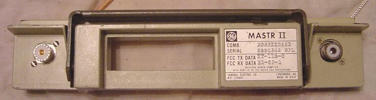
When building a repeater from a MASTR II mobile radio, a separate
receiver antenna connection must be installed. The receiver
antenna connection is added by removing the lock cylinder mechanism and
replacing it with a
quality SO-239 type "PL" or UG-58A/U type "N" chassis connector and a
"hood"
referred to as UG-177/U. I use RG-400 for the cabling since it is
double
shielded and has a tough teflon dielectric. This method provides
a
totally shielded connection that looks just like the factory antenna
port.
The original antenna connection becomes the transmitter RF output
antenna
connection.
The mobile uses some other kind of cable between the T/R relay and
the front
connector which I don't know a military RG part number for, but it has
a
clear jacket and a single layer braid. This is not ideal for
high-isolation
shielding, and it should be considered to change this cable out to
better
stuff like that suggested for the receiver, especially on higher power
UHF
or any VHF model.
If you prefer not to disassemble the radio (advanced builders) , read through the directions and install the receiver connection with care. The following instructions are provided to eliminate any danger of drilling the Systems Board or improperly installing the jumpers. Advanced builders jump here.
Caution: Remember how things are taken apart so you can reassemble the radio as it was. Make notes or take pictures if necessary.
Procedure: Remove the front of the radio set by first taking the top and bottom covers off of the radio and then removing the Exciter as well as the Receiver Oscillator/RF Casting and I-F/Audio boards from the chassis. You will need to unplug the RF cabling so remember where things go. The jumper between the receiver and antenna relay will not be reinstalled, but save it as we will be reusing the RCA connectors for the added receiver port. Next, remove the side panels and RF amplifier deck by removing the securing screws and unsoldering the large PA power leads from the feedthrough caps. This allows the front panel and Systems Board to be removed from the rest of the radio.
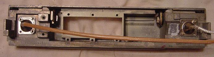
Remove the Systems Board so all that is left is the front panel casting. You will need to remove the screw holding the transistor to the casting, so be careful and save all insulating materials as they will be needed to reinstall the board to the casting. Remove the metal strap holding the power leads to the casting. Actuate the lock into the 'locked' position. This position moves the locking bar toward the center of the casting. Using a straight screwdriver, break the locking bar by inserting it between the casting and bar, putting pressure on the bar, until it breaks. Remove the lock cylinder by removing the securing nut with a wrench or large pliers. This exposes a hole that is just the right size to install the new receiver antenna connection.
Basically install the new antenna connection like the original antenna
port
making sure the coax from the connector is long enough to reach the
receiver
input connector easily. A length of about 18" or so is necessary
so
the coax can be routed around an internal controller if
installed.
Drill two holes in the casting and install the chassis connector and
hood
with small bolts and nuts of the appropriate size, I use 4-40's.
Do Not install the RCA plug on the receiver end of the coax at this
time.
This step will be done after the radio is reassembled.
Since the Systems Board has been removed from the front panel casting, now is a good time to do the Systems Board Modifications . After doing the Systems Board modifications, replace the Systems Board back onto the front panel chassis and reassemble the radio. Use fresh heat sink grease on the transistor, attached to the Systems Board, and the surface between the audio amplifier pass transistor assembly and the left side cover. This is explained in detail in Step 5.
This site, its contents, and look & feel are Copyrighted©
2001 Kevin Custer W3KKC
All Rights Reserved.