Back to Home
Communications Specialists
TS-64MSTII Modification
This article is based on a privately circulated
writeup authored by Douglas Sharp K2AD
Doug's version of June 20, 2002
HTML'd and edited by Mike Morris WA6ILQ

|
Up one level Back to Home |
Communications Specialists This article is based on a privately circulated writeup authored by Douglas Sharp K2AD Doug's version of June 20, 2002 HTML'd and edited by Mike Morris WA6ILQ |
|
The Communications Specialists TS‑64MSTII is a "motherboard" that adapts the
TS‑64DS (which is already a two-board stack) so it plugs into the MASTR II
station in place of any of the several different stock GE "Channel Guard" (CTCSS) boards.
Not only does it allow a carrier station to be converted to CTCSS without the hassle of
locating a stock CG (CTCSS) board, but it also adds functionality - the stock board is
either a decoder or an encoder, but not both at the same time...
As most stations these days need decode and frequently both encode and decode at least
one function has to be added on by a third party board, and frequently both. The
TS‑64MSTII provides decode, encode, a timeout timer and the high-pass audio
filtering (which removes the received tone from the receiver audio) all in one board,
and it is readily available (which can't be said for the GE board, even if it had all
those functions) for around US$70.00.
A note from WA6ILQ:
The only limitation is that this configuration can't do split tones... i.e. it decodes
and encodes the same tone.
The relevant Com-Spec manuals are here: (all except the last one are links to other pages at this site)
Note: Com-Spec will sell direct to the
end user and can easily beat Hutton's, Tessco's and most others prices.
Call 800-854-0547 or 714-998-3021 from 8:00am to 4:30pm (Pacific time zone), Monday to Friday
Once you have your TS‑64MSTII board in hand this modification makes the board and station combination much more usable.
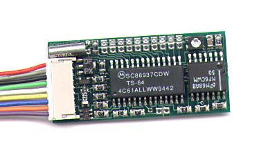
The Communications Specialists TS-64 CTCSS Encoder / Decoder
| Communications Specialists TS‑64 Wire Colors | ||
|---|---|---|
| Pin | Color | Function |
| 1 | Red | DC power in (+8vDC to +20vDC). Worst case current draw is 9 to 10 milliamps. |
| 2 | Grey | PTT Output - this is an open collector that goes to ground to enable the transmitter. This signal is the ORed result of the PTT Input plus the 160ms squelch tail elimination delay. In repeater service you will run this lead to the PTT input of your repeater transmitter. |
| 3 | Black | Ground (both logic ground and audio ground) |
| 4 | Green | Audio input - feed this pin with discriminator audio from the repeater receiver. It is the input to both the tone decode circuit and the receiver audio filter circuit (see the blue wire note below). This is a high impedance input (50-60k ohms) that needs at least 15 millivolts of audio. |
| 5 | White | Receive audio mute - While this pin is labeled as "audio mute" it's actually an open collector logic level output which goes active when the subaudible tone is decoded. This pin can be set for active high or low (configured with JP7) and is factory default active low (goes to ground when the tone is decoded). If your repeater controller has separate COR and Tone Decode inputs this goes to the Tone Decode input. If it has only one input then this pin is used as that signal. |
| 6 | Yellow | Encoder tone output (low impedance) - Up to 3 volts P-P of audio is available here, controled by the PTT input (the orange wire mentioned below). |
| 7 | Blue | Filtered audio output - The path between the green wire (in) and the blue wire (out) has a high pass / low cut audio filter in line, designed to remove the subaudible tone from the user audio. The signal from this pin gets sent to the repeater controller audio input (when using an external controller) or to the transmitter if not. |
| 8 | Orange | PTT Input - when pulled to ground this pin enables the tone encoder and puts the TS‑64 into transmit status (keys the PTT out lead and switches the tone encoder on). When ground is removed the output tone is phase shifted for 160ms, then the tone is switched off. In an environment with an external repeater controller you would use this pin to control the encoder. The PTT out (pin 2, grey) goes to the transmitter PTT in. |
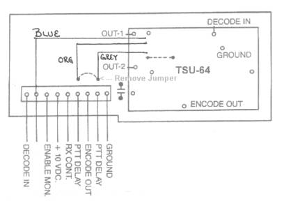
| 9 | Violet | This is a dual mode connection, and the mode depends on JP11. In repeater service
you will want to leave JP11 open (which is out as the module comes from the factory).
|
Project Steps:
Click on the photos below for a larger image
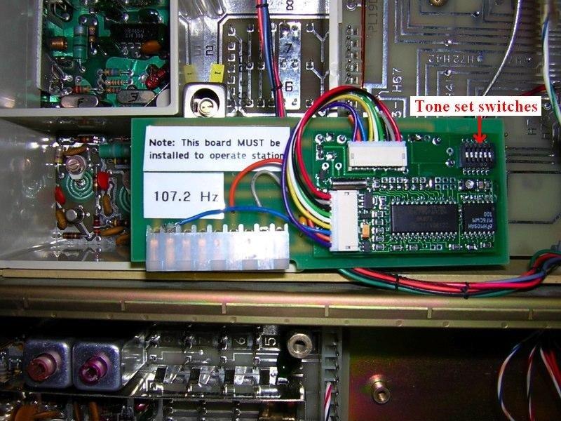
Photo 1
Here is a photo of the assembly installed in the station.

Photo 2
Any of the LBIs (service manual sections) mentioned below can be downloaded from the LBI Library here at www.repeater-builder.com.
Station Modification Steps:
Notes:
After the above cuts and jumpers are completed the board must be installed in order to have functioning receive audio and station PTT... here's why:
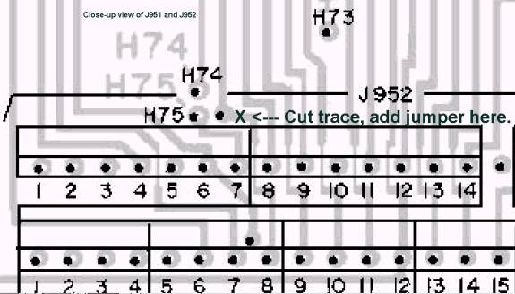
Figure 1 - From LBI31899E, the MASTR II Base Station System Board:
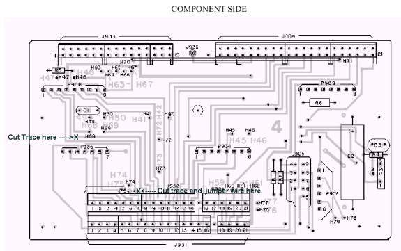
Figure 2 - An enlarged view of the lower left center of the above image:
In closing...
The TS‑64MSTII plugs into P908 on the system board, where the original factory tone board goes, with the component side of the board to the right if viewing the station shelf from the front, where you'd be standing if it were rack-mounted. Below is a shot of the whole shelf of a UHF machine, from an angle that shows where the board goes. The repeater in the photo may not look exactly like yours as ours has the factory metering kit.
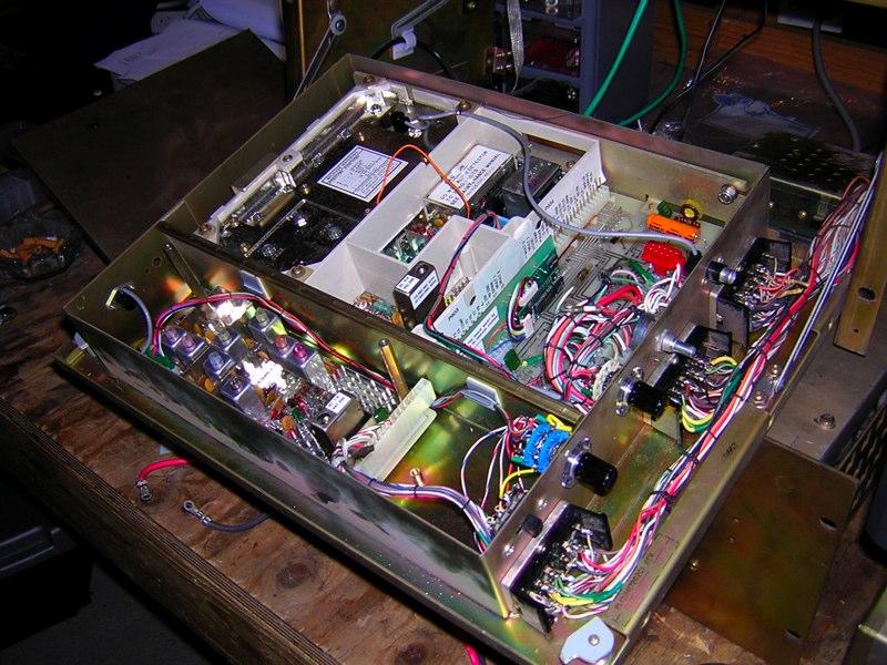
Photo 3
The only adjustments are the tone frequency (controlled by six jumpers on the TS‑64 which are connected to a six-position dip switch on the TS‑64MSTII) and the tone encoder level (which is set by the only potentiometer on the board). The board has a timeout timer on it, which should be off / disabled by leaving JP8, JP9 and JP10 un-jumpered (which is how it is shipped from the factory).
A note from WA6ILQ:
Most of my commercial two-way background has been with Motorola equipment, so I asked
Nate Duehr WYØX, an acknowledged GE fan to proofread this writeup, since he has
used this conversion several times (in fact, Nate provided the photos for this article).
In an email to me, Nate's comment on the encoder tone level pot was:
"I have never had to change/set the tone level from the TS‑64MSTII as shipped from the factory. This modification injects the TX CTCSS tone into the same input circuit to the exciter board as the GE factory CTCSS encoder, and CTCSS level can be set using only the CTCSS LEVEL pot on the exciter board, just like the factory board."
"I've never looked up what the GE exciter is expecting for tone level from the stock board, and I've never measured the output of a batch of TS‑64MSTII's to see if they're all relatively the same from the factory, but never have had to touch the adjustment on the TS‑64 itself yet when setting up this modification, nor have we seen any problems with distortion or any other CTCSS problems as a result. I guess there's always a first time for everything, eventually... but so far, no problems!"
Back to the top of the page
Up one level
Back to Home
This page originally posted on Monday 27-Nov-2006
Article text © Copyright 2002 Douglas Sharp K2AD and Repeater-Builder.com 2006
Hand-coded HTML © Copyright 2006 and date of last update by Mike Morris WA6ILQ
Top image is © Copyright Communications Specialists Inc.
LBI images are © Copyright GE and their successors.
Photographs are © Copyright Nate Duehr WYØX 2006 and used with permission.
This page created November 2006 by Mike Morris WA6ILQ from Doug's writeup and Nate's
photos with permission from both.
This web page, this web site, the information presented in and on its pages and in these modifications and conversions is © Copyrighted 1995 and (date of last update) by Kevin Custer W3KKC and multiple originating authors. All Rights Reserved, including that of paper and web publication elsewhere.