Back to Home
C100D10R to C100D30R
By Robert W. Meister WA1MIK

|
Up one level Back to Home |
Converting the Henry Radio C100D10R to C100D30R By Robert W. Meister WA1MIK |
|
The Henry Radio C100D10R is a repeater-duty UHF power amplifier that accepts 5-10 watts of input power to create 100 watts of output power. It consists of one driver stage that amplifies the 5-10 watts up to 30 watts to drive two final stages wired in parallel. A massive heat sink and three thermostatically controlled fans keep everything cool.
The Henry Radio C100D30R is identical to the C100D10R except it only needs 30 watts of input power to create 100 watts of output power. It consists of two final stages wired in parallel. A similar model C100D2R adds a preamplifier stage to the C100D10R so it can make 100 watts with only 2 watts of input power.
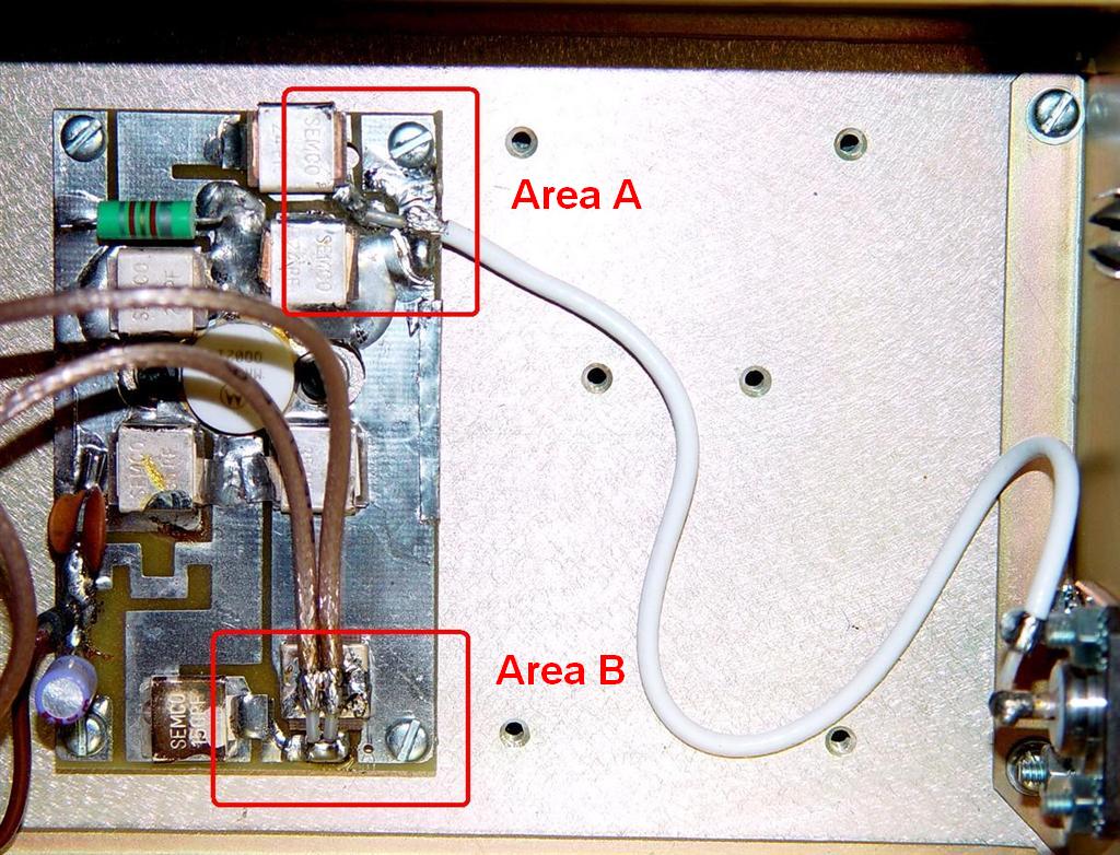
Conversion to accept higher input power consists of disconnecting the amplifier's input coax cable from the input of the driver stage, disconnecting the two coax cables from the output of the driver stage, and connecting the input coax cable to the two coax cables that feed the two final stages. It is easily reversible and only takes a few minutes to do. Common hand tools, a 30-40 watt soldering iron, and a 100 watt soldering gun are all you need. Just follow the steps below. Click on any photo for a larger view.
Here's the driver stage from the original C100D10R amplifier.
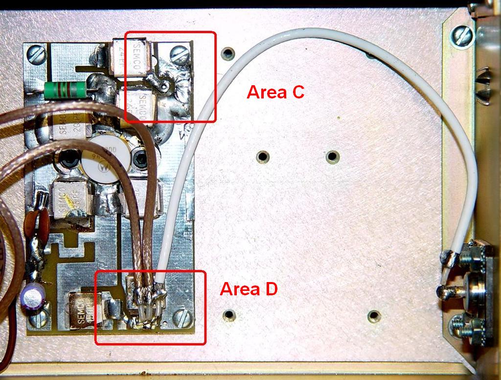
Here's the driver stage from the rewired C100D30R amplifier.
Schematics of the C100D10R and C10D30R can be found here. You can scroll through the two pages and see the wiring difference.
Before and After Performance:
The following table summarizes the performance of this amplifier. It was driven by a Motorola MaxTrac mobile radio with manual power control on its own Astron RS20 power supply. The amplifier used an Astron RS35M power supply set to 14.0VDC. RF input power was measured with a CDI 81050 wideband wattmeter. RF output power was measured with a Bird 43 and a 100w UHF element.
| Parameter > | In Pwr | In Refl | Out Pwr | Amps |
|---|---|---|---|---|
| C100D10R "before" | 5w | 0.1w | 100w | 18 |
| C100D30R "after" | 33w | 1.2w | 100w | 14 |
The reflected power of the converted amplifier is higher because the two final amplifier stages are running in parallel and do not present a 50 ohm load to the radio.
An Alternative:
If you have the money floating around, you could install a 6dB, 25 or 50 watt hybrid attenuator at the input of the amplifier. This would raise the drive power requirement by a factor of 4, so instead of 5-7 watts, you'd need 20-28 watts of drive power to achieve the same output power. Now, to me, this is wasteful as it takes 20-28 watts, drops it down to 5-7 watts, only to get amplified by the first stage back up to about 30 watts then up to 100 watts by the remaining stages. The amp would also draw the same DC current as it did with 5-7 watts of drive, but it might be cleaner and easier for some people. You would have to mount the attenuator inside the amp, unless you get a coaxial attenuator with N-F and N-M connectors and install it outside the amp, in series with the input signal. The input attenuator will also improve the input return loss of the amplifier, which may be beneficial in some situations. Henry Radio sells 25 and 50 watt attenuators with various levels of attenuation starting at about $30US. See their online or ebay shopping portals.
Contact Information:
The author can be contacted at: his-callsign [ at ] comcast [ dot ] net.
This page created 05-Aug-2017.
Go to the top of this page
Back to Henry Radio index page
Go to Home
Article text, layout, photos, and HTML © Copyright 2017 By Robert W. Meister WA1MIK
This web page, this web site, the information presented in and on its pages and in these modifications and conversions is © Copyrighted 1995 and (date of last update) by Kevin Custer W3KKC and multiple originating authors. All Rights Reserved, including that of paper and web publication elsewhere.