Back to Home
Compiled, HTML'd and maintained by Mike Morris WA6ILQ

|
Up one level Back to Home |
Some notes on interfacing to the Kenwood TKR-720 and TKR-820 tabletop repeaters Compiled, HTML'd and maintained by Mike Morris WA6ILQ |
|
This is a "quickie" page that was put together in late January 2008
as there was a converation on the repeater-builder mailing list that asked some
questions about interfacing a TKR-720 to an Scom repeater controller. I pulled my
two pages of handwritten notes from from my file cabinet and provided some info
from when I had to interface a TKR-720 and a TKR-820 to Scom controllers and
made this web page from them. The second pass a few months later added the TS-64
notes.
Please don't email me asking for any other info as everything in that project
file folder is here and I no longer have access to those TKR-n20s.
This web page is not pretty but it works. If someone has a TKR-n20 repeater and wants to add some photos or additional info to this page just email me at (mycall) at repeater-builder dot com. If anyone wants to write an additional article just let me know – or even a replacement article that builds on this information.
The TKR720 (VHF) and TKR-820 (UHF) are / were tabletop or rack-shelf-mount repeaters and were derived from the TK-720 and TK-820 mobile radios. The VHF and UHF TKRs interface the same. If Kenwood sticks to its numbering plan a low band unit would be a TKR-620 if they ever made one. In this writeup I'm going to use the format of TKR-n20 just to keep things generic.
Note that the TKB-n20s are the base station version and may interface differently. I've not had access to one to find out.
While the KSG-4500 is basically a TKR-820 with a 100 watt continuous duty amplifier and power supply built in (and fits in 4 rack units!), the interfacing is not the same. First, the KSG uses a DA-15 accessory connector where the TKR uses a Molex 15 pin, second the pinout is completely different, and third you have to go chasing internal changes - such as finding a soldered jumper the on the "Repeat" button (locking it in repeat). There are PDFs of a TKR service manual and a preliminary manual on the KSG on the Kenwood page at this web site.
Again, this page is a collection of NOTES, not a step-by step procedure. You
may have to play with some of the connections to make them work, as I took the
notes as I did the work, and I may have missed writing something down.
I also used the internal decoder on one TKR and a TS-32 decoder on another, and
my old notes are not clear as to what was different between the two. If anybody
wants to take what is here and write a real article from it, feel free to. And
things change in Kenwood's production - for example, the earliest TKR-n20s didn't
bring out tone decode to the accessory connector - the repeater might be programmed
for tone, but the COS pin was a carrier indicator, not a receiver unsquelched
indicator.
So these notes are accurate as of the date I did the work described below, and
there is no guarantee that later units will work the same.
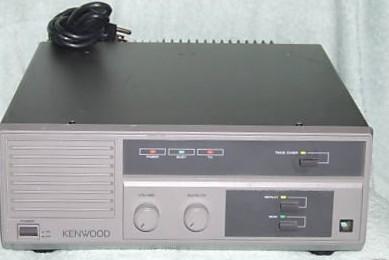
The rectangle at the lower left is the power switch.
The square at the bottom right is the 6 pin(!) microphone jack (NOT an 8 pin).
The KMC-14 mobile microphone works just fine.
The white rectangle at the lower left is the accessory connector.
This is described in excruciating detail below.
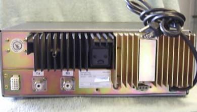
The TX and RX antenna connectors are SO-239. This was a surprise
for the owner of the TKR-820 that he had me bench and tune up as
everything he has on UHF comes with "N" connectors.
The connector under the middle of the gold-colored heat sink is for
an external 12 volt backup battery or other DC source.
Bandsplit information:
Look for the FCC ID number on the serial number tag on both the TKR units and the KSG units.
Output power:
Keep in mind that the TKR-n20 is rated for 100% duty cycle at only 5 watts
and below, and 50% duty cycle at 20 watts. Power is set by VR1 on the PA
assembly. There is a properly placed hole in the sheet metal for a non-metallic
screwdriver to adjust it. Resist the temptation to put a fan on it and run it
at a higher power... fans fail and you will burn up your PA, then discover that
replacement PA decks are no longer available and expensive to fix (if they can
even be fixed). You will be much, much happier if you run it at 5 watts or less
and put an external continuous duty amplifier behind it. Henry Electronics in
Los Angeles makes good ones that do 5 watts in and 100 watts out...
Duplexers:
These units an be found with an internal duplexer, but it's a flat-pack notch-only
duplexer which is NOT appropriate for a busy site. The quick test is to look
on the rear and if you see one coax jack then you have an internal duplexer or if
you see two coax connectors (separate transmit and receive) then there is no
duplexer option. Finding a VHF unit (a TR-720) with an internal duplexer is RARE,
and when you do, it's one with a multi-megahertz offset. The TKR-720 that I worked
on had a duplexer designed for a 5 Mhz or more offset and therefore wouldn't work on 2 meters.
Repeater Features:
In short, very little in the way of bells and whistles. It has a carrier delay
(hang-in) timer, a time-out timer, and does not have an IDer. It has CTCSS and
DCS encoding and decoding built in. The tone encoder doesn't generate true
reverse burst. Just like many other manufacturers the TKR tone encoder tone
is shut off a very short time before the transmitter carrier drops.
RF Frequency Programming:
There are three ways to program a TKR-n20:
The K3MK method involves carefully unsoldering the 9346 chip that holds the RF frequency information and installing a 8-pin DIP socket where the chip was. Then the old chip (or a replacement) is programmed per the instructions in the article using a common chip programmer, and then plugging the reprogrammed chip into the new socket. The same is done for the PL Tone / DPL Code chip (also a 9346), but that one is already socketed from the factory. If you remove the PL Tone / DPL Code chip from the socket then your repeater drops into carrier squelch mode.
Tuning:
The proper way to align the front end is to use the internal sample port, but
rough guess tuning by most seems to work OK. I really suggest getting a manual
(or downloading the service manual file from this web site) and read the tuning
section.
Interfacing the TKR-n20 units:
| 15-Pin Accessory Connector Info | |||
|---|---|---|---|
| Molex Part Numbers | Digikey Part Numbers | Mouser Part Numbers | |
| Housing: | 03-06-2152 | WM1228-ND | 538-03-06-2152 |
| Pins: | 02-06-2103 | WM1000-ND | 538-02-06-2103 |
Information I don't have: (can somone provide them?)
1) a photo of the connector inside the TKR where the KPT programmer plugs in.
2) Connector info and amp-hour sizing info for the backup battery.
3) Some computer screenshots of the Kenwood software used with the KPT-50, plus any relevant notes.
| The TKR-n20 Accessory connector | |
|---|---|
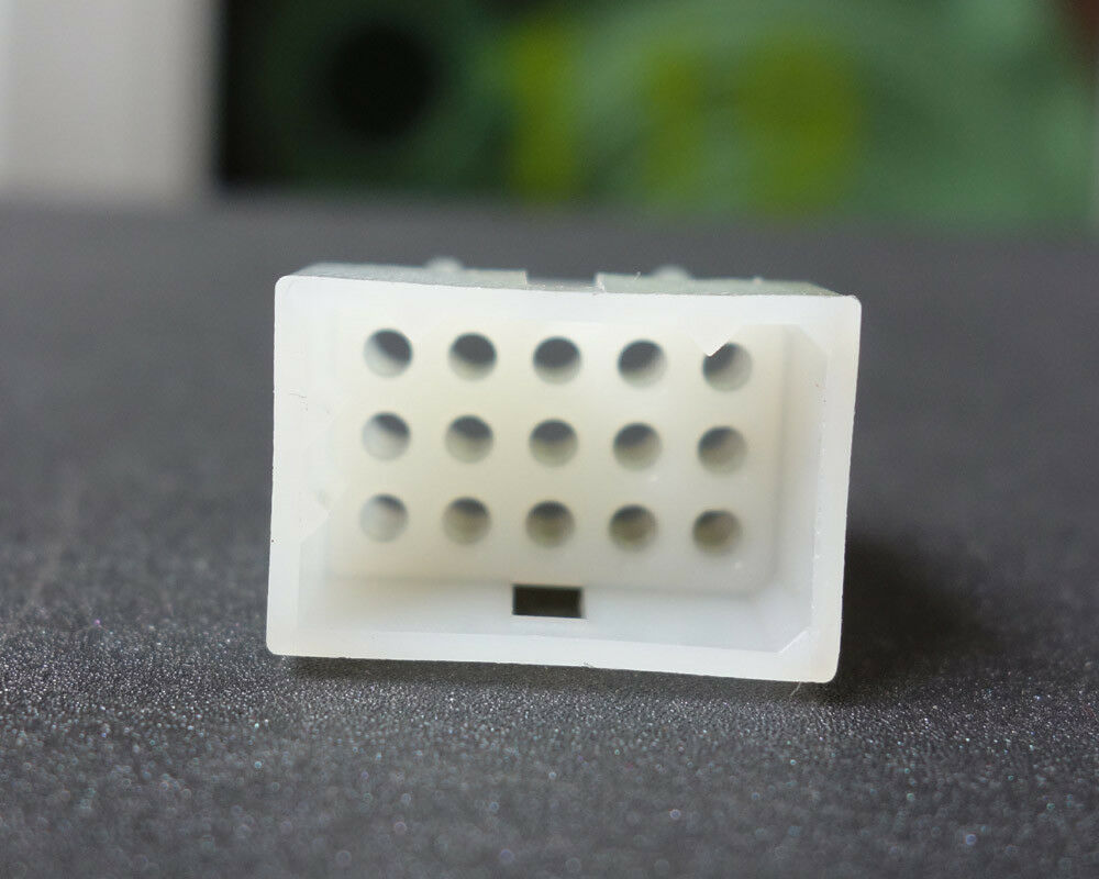
| Pin Layout: (looking at the rear of the unit) The connector is five rows of three pins across in this format: 4 5 6 7 8 9 10 11 12 13 14 15 |
|
|
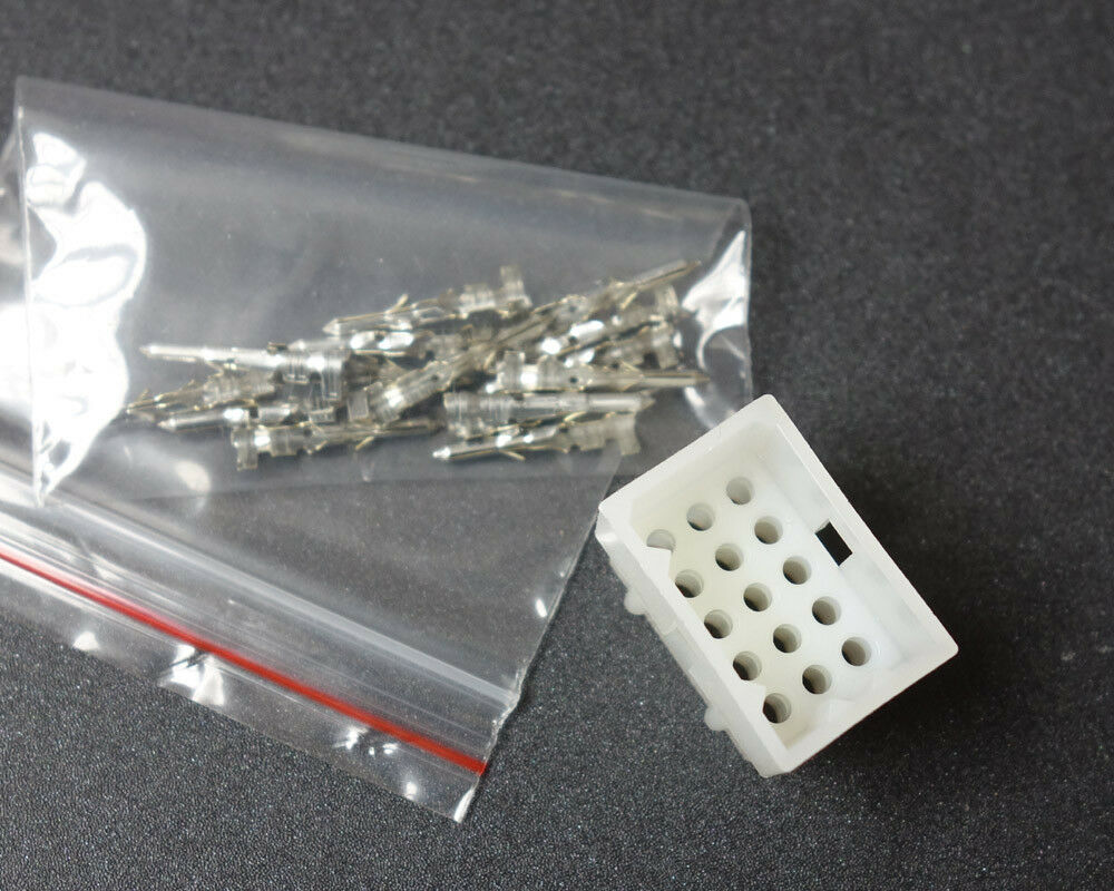
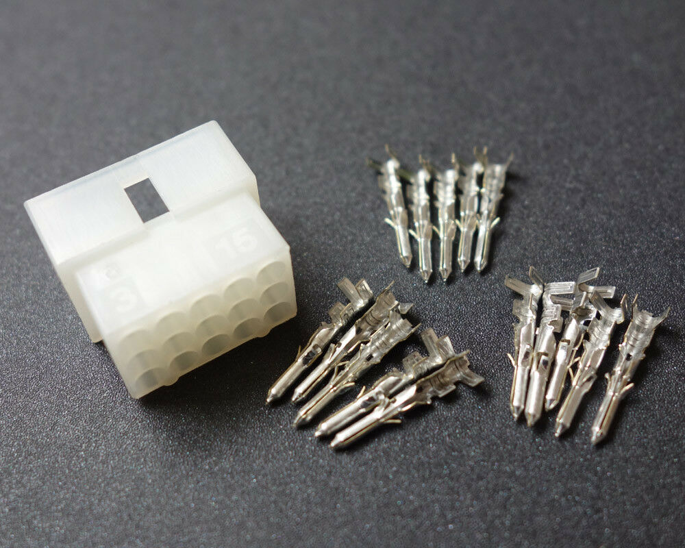
Note that the connector in the TKR is a male body with female pins!
You need to purchase a female socket and male pins. Here are some
photos:
1
2
3 Unless you have a good electronics store close by you will probably have to order from Mouser or DigiKey. |
|
| Pin | Description and Notes |
| 1 | Internal Controller disable - Jumper to pin 11 (ground) - grounding this pin tells the TKR to disable the internal controller completely and use an external controller, except the PL encoder / decoder is still operational. Set the "tone" number in the programming to zero for carrier squelch, otherwise set it for the tone you want. |
| 2 | Audio ground. |
| 3 | Transmitter modulator in (used as external CTCSS tone encoder injection input - don't use this pin for anything else). If you are using shielded cable - recommended - tie the shield to pin 2. |
| 4 | Receiver discriminator out (connect this to the audio input of any external CTCSS or DCS decoder(s) here, otherwise don't use). If you are using shielded cable - recommended - tie the shield to pin 2. |
| 5 | Transmitter audio in (i.e. repeat audio from the external controller). If you are using shielded cable - recommended - tie the shield to pin 2. |
| 6 | External speaker ground (see pin 12) (jumper this pin to pin 11) |
| 7 | +12vDC out of the TKR. This pin will source up to 1 amp so you can power an external controller from this pin. My old notes don't mention if this pin is fused inside the TKR (or if it's fused separately from the radio electronics), so until you check be careful that you don't short it to ground accidentally. You don't want to melt a trace or a wire in the harness. |
| 8 | PTT input (ground to xmit) (see note 1) |
| 9 | Internal speaker (jumper to pin 12 to enable) |
| 10 | De-emphasized receiver audio (i.e. repeat audio out to the external controller). If you are using shielded cable - recommended - tie the shield to pin 2. |
| 11 | Ground |
| 12 | Internal speaker audio out (jumper to pin 9 to enable) Do not use this pin as a source of repeat audio. This is monitor audio only. |
| 13 | RUS out (see note 2) |
| 14 | Empty hole in the connector body (see note 3) |
| 15 | Empty hole in the connector body (see note 3) |
Table notes:
Using the above information, the Repeat, Monitor and Take-over buttons on the front panel will be in the "out" position.
If you want a system that is remotely switchable between carrier and tone (which I do on every repeater I build, and is very handy when you are trying to figure out what the grunge is) you need to do one of three things:
| Notes on the Com-Spec TS-64 tone decoder | |
|---|---|
| Wire Color |
Signal Description and Notes |
| Red | + DC power in |
| Black | Ground |
| Green | AUDIO INPUT. Hook this to the receiver discriminator |
| Violet | HANGUP input. Ground this pin to make it active. When it's floating the tone decoder is disabled. When it's grounded the tone must be present. |
| White | MUTE - This is the actual tone decoder output signal. It is an active high open collector output, and it requires a pullup resistor (1K works fine). If the signal is upside down from what you need then install jumper JP7 to get an active low signal (it will go to ground on decode). |
| Yellow | ENCODER output. This audio output is connected to the transmitter modulator. |
| Orange | PTT input. Ground this to switch the tone encoder on. When ground is removed the encoder phase is shifted (i.e. reverse burst), and the encoder stops when the 160ms is over. In our application we connected the PTT output of the external repeater controller to this pin. |
| Grey | PTT Output. This signal goes low when the orange wire is grounded and stays low for the duration of the grounded input plus the reverse burst timing. In normal radio usage the PTT lead from the microphone would be disconnected from the radio and be connected to the orange wire, and the grey wire be connected to the point in the radio where the microphone PTT lead was. In our application this pin went to the transmitter PTT input. |
| Blue | FILTERED RECEIVE AUDIO OUT. The path from the green wire (in) and the blue wire (out) has a high pass / low cut audio filter in line, designed to remove the subaudible tone from the user audio. This is an installers choice - You can feed the blue wire back into the receve audio connection. This type of radio surgery is very radio dependent and cannot be covered here. Many radios have a tone removing high pass filter in them from the factory and in that case you can simply tape off the blue wire and ignore it. |
All of the above TS-64 information is in the Instruction Sheet that is packed with the TS-64 itself. In addition it can be downloaded from the Com-Spec web site, or from the TS-64 page at this web site.
I included the TS-64 info above instead of the TS-32 as it's a current product, and easier to use. If you take the above info, a TS-64 data sheet and a TS-32 data sheet and compare them you can figure out the hookup of a TS-32.
Contact Information:
The author can be contacted at: his-callsign // at // repeater-builder // dot // com.
Back to the top of the page
Up one level
Back to Home
This page originally posted on 28-Jan-2008
Article text and hand-coded HTML © Copyright 2008 and date of last update by Mike Morris WA6ILQ
This web page, this web site, the information presented in and on its pages and in these modifications and conversions is © Copyrighted 1995 and (date of last update) by Kevin Custer W3KKC and multiple originating authors. All Rights Reserved, including that of paper and web publication elsewhere.