Back to Home
100 watt Amplifier to 6-meters
By John Haserick W1GPO
and Dave Malicki N1OFJ
Compiled by Robert Meister WA1MIK

|
Back to MICOR index Back to Home |
Converting the Micor Low-Band 100 watt Amplifier to 6-meters By John Haserick W1GPO and Dave Malicki N1OFJ Compiled by Robert Meister WA1MIK |
|
Background:
The TLB1414C is a 100-watt continuous-duty low-band power amplifier used on Micor stations. It consists of the following modules and sub-assemblies:
| Number | Description |
|---|---|
| TFB6024A | Harmonic Filter (42-50 MHz) |
| TLB6940A | Power Control Board |
| TLB6954A | Power Amplifier (42-50 MHz) |
| TLN4746A | Hardware Kit |
| TLN4780A | Casting Assembly |
| TLN4807A | Capacitor Network (42-50 MHz) |
| TLN4823A | Input Bracket and Cable (Earlier) |
| TRN8013A | Input Bracket and Cable (Later) |
The input power requirement is typically 400-600 milliwatts. The book says the amp draws 20.5 amps at 12.8 volts. A stock amp produces the full 100 watts at 50.0 MHz but considerably less at 54.0 MHz, due primarily to the harmonic filter.
Unlike its mobile counterpart, the low-band continuous-duty station PA has its Power Control Board (PCB) on the same heat sink with the PA board. This adjusts the A+ voltage to the first amplifier stage. Like the VHF version of the PCB, you need to supply keyed A- to the amp. This is on a pin on the input end of the amp. Connect this pin to the A- supply terminal, NOT CHASSIS GROUND, when you want the amplifier to be activated, because the amp, like most Micor products, can be configured to run on positive or negative ground systems. All of the transistors are NPN, not PNP as in the Micor high-band amps.
I have converted at least six of these to 6-meters and they are being used on several 6-meter repeaters in New England. The latest version that has white instead of grey PA transistors requires a fewer component changes. I run mine at 110-115 watts out, but there are timed drop-out fans, including a muffin fan on the front screen blowing on the board, plus fans drawing air from the cooling fins out the cabinet, and the ambient temperature in my basement stays below 72 degrees. I have burned out two PAs that were running over 100 watts out without all these fans, so I recommend no more than 100 watts out or 26 uA on metering position #5 (PA meter current) at 13.8 volts on the PA terminals. The meter indication, when divided in half, equals the total PA current in Amps, so 26 uA means 13 amps, and at 13.8 volts that gives you 179.4 watts of input power.
Doing the Conversion:
It goes without saying that you should verify that the amp works properly in its designed range of 42-50 MHz BEFORE you begin modifications.
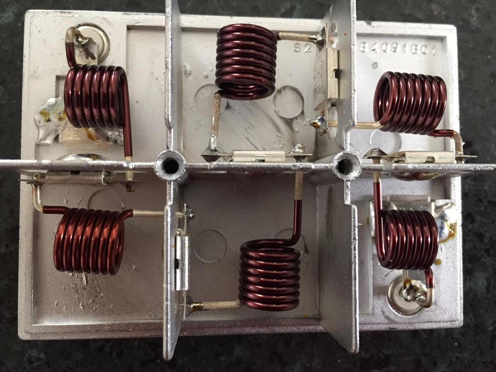
You will be working on the harmonic filter and PA board. The harmonic filter is the limiting factor in the amplifier's operation above 50 MHz. Here's a photo of the stock harmonic filter. Click on any image for a larger view.
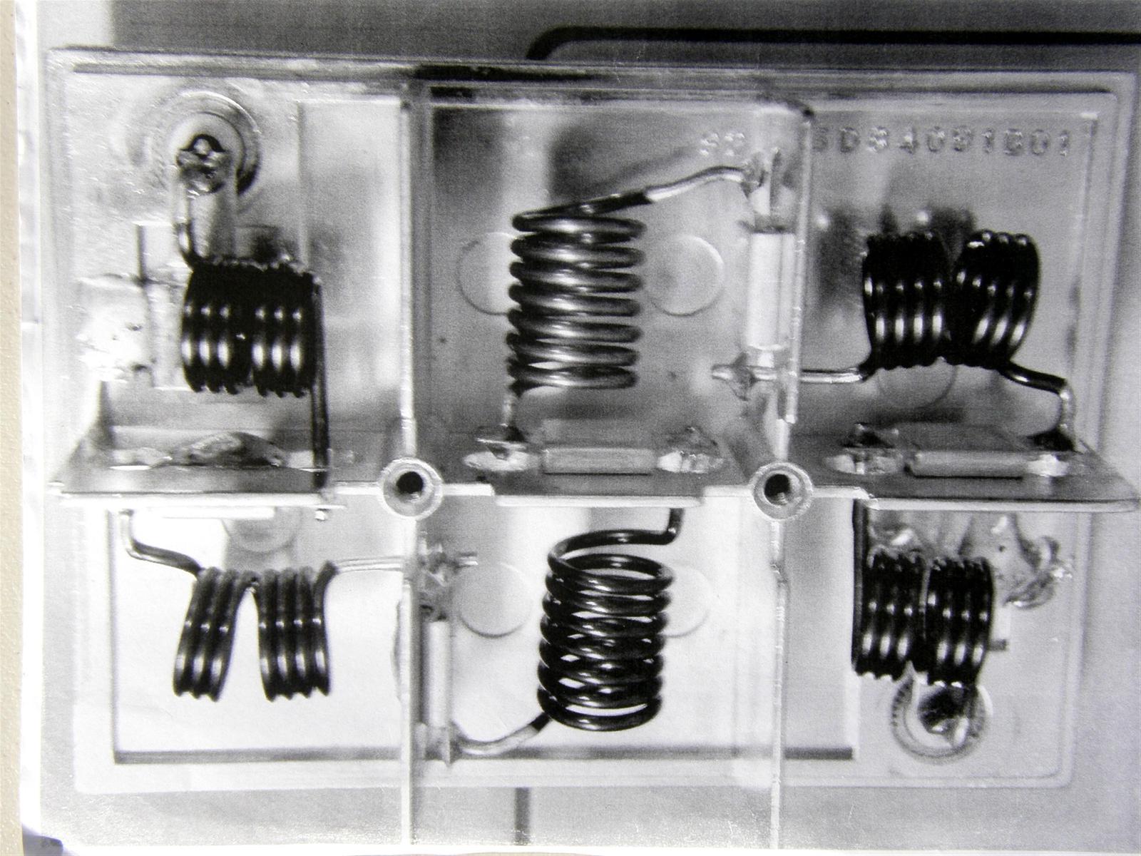
Here's a photo of a modified harmonic filter.
Several components need to be changed on the PA board, as shown below. Refer to the X-ray view below. The silver mica caps are 500 volt, 5 % tolerance.
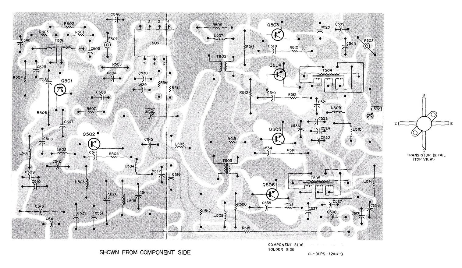
Reinstall the PA board and the power control board. For completeness, here's the schematic of the PA board as a 64 kB PDF file.

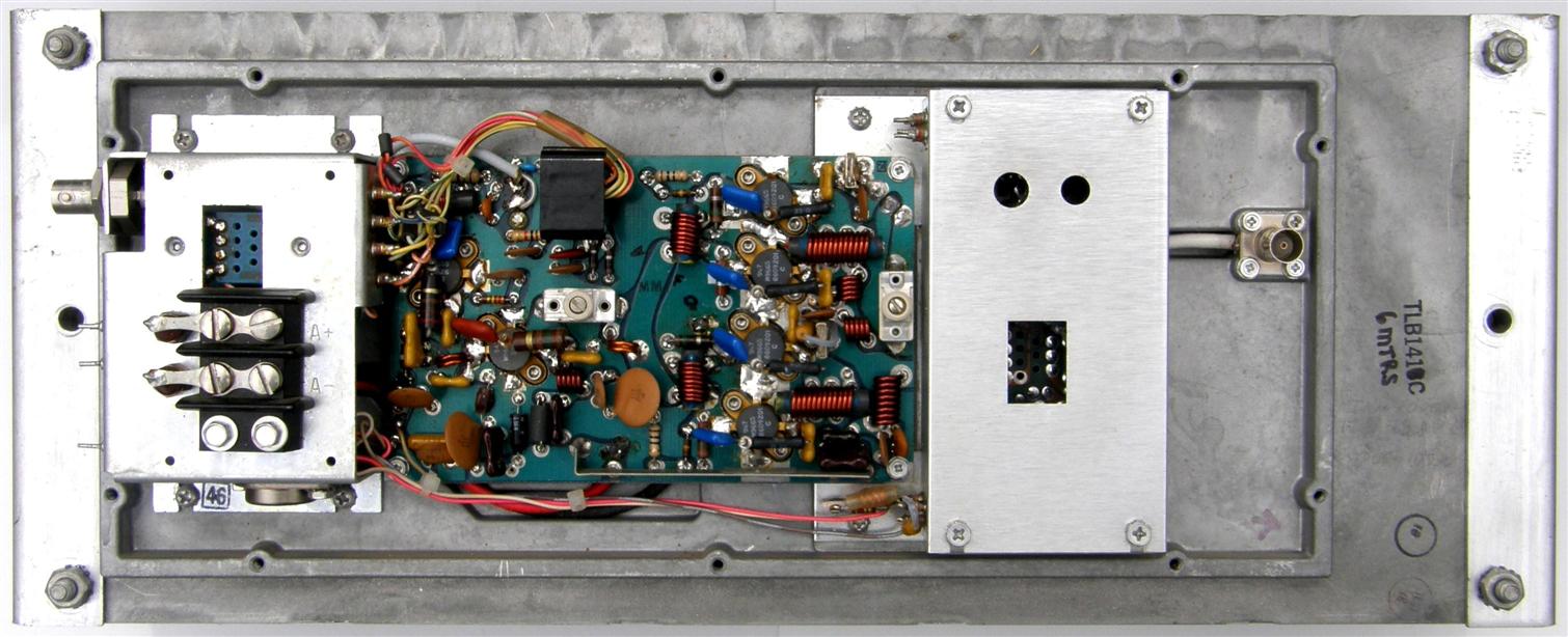
Here's a photo of a converted amplifier. The input jack is on the left side. The yellow-orange mica caps are the new value replacements. The four vertically on the right side of the PA board are the 47 pF micas. The original 1/2 turn coil (L502) between the pre-driver and the driver on the left was replaced with a 1-1/2 turn coil to match the existing 1-1/2 turn coil on the right, which is at the output of the driver. The Power Control Board is under the metal cover towards the right, and the RF output connector is to its right.
The entire 100 watt PA section from the low-band station manual is available here as a 2.3 MB PDF file. The tune-up procedure for the amplifier is at the end of this file.
The entire VHF Power Control Board section from the low-band station manual is available here as a 3.6 MB PDF file.
Additional Modifications:
Some PAs may be a later revision level. The schematic has some notes on it that show alternate parts values for this condition. The following parts changes on the PA are optional but were found to be unnecessary on most PAs.
To update to the latest revision, change L502 from 1/2 turn to 1-1/2 turns, making it the same as L505. Use 16 gauge enameled wire. If you do this, then change R504 from 10 ohms to 1.8 ohms 1/2 watt carbon film. Also change C507 to 250 pF CD15 size, change C508 to 390 pF CD19 size, and change C512 to 470 pF CD19 size. Both Mouser and Digikey stock silver mica capacitors at between $1.75 and $3.50 each.
Operational Notes:
The output compression cap will tune almost unscrewed, so to decrease the minimum capacitance for more tuning range, remove the screw, spread the top plate portion out and back and then reinstall the tuning screw.
Do not exceed 180 watts input power, i.e. 26 uA at PA meter #5 at 13.8 volts on the PA terminals. If the output is set for more than 100 watts, multiple cooling fans are required. The photo below shows one way of mounting a fan to the screen cover. We use timed fans on the PA screen and the heat sink plus a room temperature below 72 degrees to allow 110-115 watts out with 14.3 volts at the PA terminals and 26 uA of PA current. The normal power consumption for the entire amp is 18 amps at 13.8 volts, measured at the A+ and A- screw terminals, for 100 watts output. When the PA is tuned for maximum efficiency by detuning C502 about 2 turns from peak, power consumption for the entire PA at 13.8V is 17 amps for 100W output. Input reflected power should be less than 0.04 watts for 0.4 watts out of the exciter.

Some advice given to me by one of the original Motorola Micor designers is not to run the power control pot fully clockwise (for a maximum of 12 volts on the pre-driver), as there is danger of overdriving the subsequent driver and output power transistors, which will, over time, cause them to lose gain. Apparently this was often done to compensate for worn out or overheated output transistors, then the driver or pre-driver became damaged also. Try to keep the pre-driver voltage below 10 volts. A good PA should require around 6 volts to the pre-driver for 100 watts output. An exception to running the pre-driver at the maximum voltage is if its gain has deteriorated from being overdriven or overheated, or the base resistor has increased value. Keep the input power under 1 watt. The input VSWR should be less than 1.7-to-1 but it may vary depending on the capacitor values around L502 and the current draw of Q501.
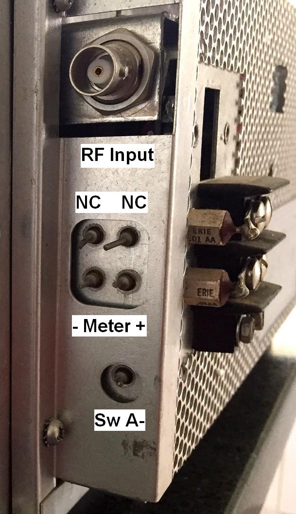
The left side of the amplifier has five feed-through capacitor leads exposed to the world plus the input RF BNC connector. See the photo below. Wires with push-on connectors attach to some of those feed-through caps. The "- Meter +" terminals are directly across the PA current meter shunt (PA metering jack pins 5 & 6) and would be used where a permanent PA Current meter is present in the station. The "Sw A-" terminal needs to be connected to A-, NOT chassis ground, to enable the PA. This feeds the Power Control Board and should be pulled to A- when the exciter is putting out RF power, not necessarily when the PTT input to the station is active, since reverse-burst or the DPL turn-off code would delay the exciter turn-off after PTT is released.
Acknowledgements and Credits:
Schematic diagrams, alignment procedure, and circuit board X-ray views came from the Micor Low-band Station Manual 6881013E60-G, courtesy of John W1GPO.
Photographs were taken by the authors and are copyright by them.
Contact Information:
John can be contacted at: jhaserick84 [ at ] comcast [ dot ] net.
Dave can be contacted at: his-callsign [ at ] comcast [ dot ] net.
This page was created 23-Apr-2017.
Go to the top of this page
Back to the MICOR index page
Back to the Home page
Article text and photographs © Copyright 2017 and date of last update by
John Haserick W1GPO and Dave Malicki N1OFJ.
Layout and HTML © Copyright 2017 by Robert W. Meister WA1MIK.
This web page, this web site, the information presented in and on its pages and in these modifications and conversions is © Copyrighted 2017 and (date of last update) by Kevin Custer W3KKC and multiple originating authors. All Rights Reserved, including that of paper and web publication elsewhere.