Back to Home
By M. Scott Zimmerman N3XCC
and by Mike Morris WA6ILQ

|
Up one level Back to Home |
Schematic diagrams and other information about MICOR channel elements By M. Scott Zimmerman N3XCC and by Mike Morris WA6ILQ |
|
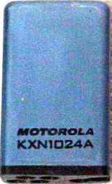
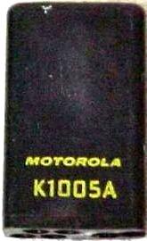
The MICOR was a follow-on series to the Motrac, Motran and Mocom-70 series of mobile radios The concept of the "Channel Element" - a sealed crystal oscillator that held all of the frequency determining parts - was developed in the middle of the Motrac line. The MICOR element used the same physical form factor as the Motrac and hence the same pin spacing and assignments The Motrac and Motran elements came in color coded anodized cases - blue for ±0.0005% or gold for ±0.0002% Later on the anodite treatment was dropped (as a cost saving measure) and elements started showing up in natural aluminum Even later they cut costs further and went to a plastic housing. You will find MICOR elements in black, blue and gold anodite, in natural aluminum, and in black plastic cases In general you will find that a blue anodite element (photo) is ±0.0005%, and a gold anodite element is ±0.0002%. Some MICOR elements were made with black anodized aluminum housings (anybody have a photo?) At some point during the MICOR product line they dropped the colored cases and went with plain aluminum (see the group photo below). Later they dropped the aluminum altogether and went to 100% black plastic cases (photo) to reduce manufacturing costs. Just look at the part number - no matter the case style they are electrically identical.
The connector bases of the early MICOR channel elements, like the earlier ones used in the Motrac, Motran and Mocom-70 products, came in three-pin and four-pin versions. Later on they dropped the three-pin base and used the four-pin plastic part for everything - if a three-pin element was being made they just left the 4th metal insert out of the base The three-pin channel elements were used for either receive (non‑AFC) or phase modulated transmitters The four-pin channel elements used the extra pin as modulation audio (transmit) or AFC control voltage (receive). One classic trick is to swap a K1007 (three-pin, phase modulator) into a transmitter that normally uses a KXN1019 (four-pin, FM modulator internal to the element) and watch the new tech spend hours trying to figure out why there is no transmit audio.
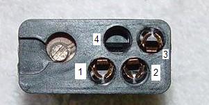
If you look carefully you will see that the hole for pin 4 has no metal insert in the plastic body.
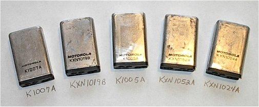
This photo several shows metal cased elements. Externally there is no real difference other than the part number, and that some have three pins and others have four pins. Internally there are big differences.
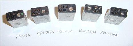
If you look closely at the photo the K1005 and K1007 elements have 3 pins in a 4‑pin body (as shown above). Not shown in this photo are the K1003, K1004 and KXN1029 that also have 3 pins. All the other MICOR elements in the photo above have 4 pins.
| MICOR Channel Elements See the end of this writeup for the Palm Pilot version The element schematics and layouts were reverse engineered back in the 1980s and were donated. If anybody wants to do any more and donate them please do so. |
|||
| Element Part Number |
1=see note below Usage1 |
Accuracy2 | Notes, etc. |
| K1003 | Low band and mid band receiver | ±0.0005% | See this article: What's inside a K1003 Channel Element |
| K1004 | Low band and mid band transmitter | ±0.0005% | Three pins, phase modulated and as such will not work with DPL (see KXN1028) |
| K1005 | High Band receiver 5 | ±0.0005% | Station, Mobile and Railroad |
| K1006 | High Band receiver 5 | ±0.0002% | Must be used with the TLN1362A or TLN4440A AFC Amplifier Used in Station, Mobile and Railroad radios |
| K1007 | High Band transmitter (PM - 3 pins) | ±0.0005% | Mobile and Railroad Will not work correctly in a FM exciter as used in a Station or Repeater |
| K1037 | Low band transmitter | ±0.0002% | Mobile |
| K1038 | Low band receiver | ±0.0002% | Mobile |
| KXN1018 | High band transmitter (FM - 4 pins) | ±0.0002% | High Stability Repeater and Station |
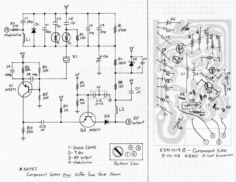
| KXN1019 | High Band transmitter (FM - 4 pins) 7 | ±0.0005% | Repeater and Station. Also Mobile with DPL KXN1019 Schematic and Layout |
| KXN1021 | Low band receiver 6 | ±0.0005% | Used only in the second receiver of dual receiver low band stations (has the IF shifted to 5.36 MHz) |
| KXN1022 | High band receiver 5, 6 | ±0.0005% | Used only in the second receiver of dual receiver high band stations (has the IF shifted to 11.8 MHz) |
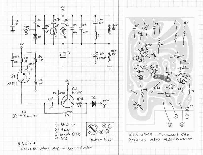
| KXN1024 | UHF receiver | See notes 3 and 4 |
Station, Mobile, EMS Mobile, etc. KXN1024 Schematic and Layout |
| KXN1028 | Low and Mid band transmitter | ±0.0005% | DPL transmitter |
| KXN1029 | UHF 8 and 900 MHz 9 receivers | ±0.0002% | Station, Mobile, Mobile EMS, Trunked Station, Trunked Repeater (non‑AFC) |
| KXN1044 | Low band DPL transmitter | ±0.0005% | Mobile DPL |
| KXN1045 | High band DPL transmitter | ±0.0005% | Mobile DPL |
| KXN1050 | High band DPL transmitter | ±0.0002% | Mobile DPL |
| KXN1052 | UHF transmitter | ±0.0002% | Station only 4, 7 |
| KXN1068 | 800 MHz trunked receiver | ±0.0003% | |
| KXN1071 | 800 MHz trunked transmitter | ±0.0001% | C45RCB, etc. |
Notes:
| 1) | Low band = 25‑50 MHz, USA Mid Band = 72‑76 MHz,
non-USA Mid Band = 66‑88 MHz, High Band = 136‑174 MHz,
UHF Band = 406‑520 MHz. PM=Phase Modulation, FM=Frequency Modulation. |
| 2) | Standard accuracy is ±0.0005%, high accuracy is ±0.0002%. |
| 3) | The KXN1024 is nominally ±0.0005% but with the AFC working properly it can hold ±0.0002%, but that does not get around the written type acceptance rules that require KXN1029s in ±0.0002% environments such as GMRS (and besides, the KXN1024 is used in the mobile transmitter and the AFC is disabled during transmit). |
| 4) | The UHF mobile uses one KXN1024 element for receiver, transmit simplex and transmit repeat. Kevin wrote an excellent article on the theory behind the UHF MICOR mobile that explains how it all works. The UHF station uses a KXN1024 (±0.0005%) or KXN1029 (±0.0002%) for receive and a KXN1052 for transmit. The KXN1052 is an FM transmit element and the internal modulator is used in the Station for voice, PL, and DPL modulation. |
| 5) | For receivers in the 132‑151 MHz range order your crystals for HIGH SIDE injection. |
| 6) | There is no difference inside the element between one made for a second receiver and one made for a primary receiver except for the element part number on the outside of the housing. The changed part number just clued the rock chippers to cut for the alternate IF frequency. For example, if you need a KXN1022 (rare!) you can use a K1005 (very common), just be very, very specific when you order the crystal that it is for the 11.8 MHz second receiver offset IF (the standard IF is 11.7 MHz). |
| 7) | The UHF station transmitter uses a high band element because it's a high band exciter followed by a tripler to 450. To my knowledge the KXN1019B and KXN1052A are exactly the same with the exception of a few internal resistor values that lowers by 2/3 the amount of applied audio delivered to the modulator that is inside the element. This change is necessary, of course, because of the multiplication factor of the UHF unit operating at 3 times that of VHF. This change in value allows for a similar setting position of the "IDC" control to result in 5 kHz deviation. I suspect (but have not tried this) that you could plug a KXN1019 into a UHF transmiter and as long as you were very, very careful with the deviation setting it would work just fine. |
| 8) | As said above, the UHF mobile uses one KXN1024 element for receive, transmit simplex and transmit repeat If you "flip over" the injection as part of moving the radio from commercial to amateur frequencies you will discover that the receive AFC will pull the transmit frequency off frequency. The cure is to flip over the AFC diodes (difficult), short out the AFC (easy) or swap the KXN1024 element for a KXN1029 element (which ignores the AFC pin, and is a waste of a high accuracy element). While AFC is not as important these days as when the MICOR was new in commercial service, you really want to read the article mentioned in note 4 above for more details. |
| 9) | The 900 MHz uses a KXN1029 element that has a spec of ±0.0002%. It also uses a multipler of 48 times the crystal to generate the local oscillator injection frequency. The simple frequency drift caused by the temperature swing from a cold night to a warm day when multiplied by 48 is more than the receiver bandwidth. On 900 MHz you really, really want to send the element back to the crystal house for temperature compensation. In early 2007 a new crystal installed and compensated was about $50 from International. A good alternative to expensive temperature compensation is the CH25 Crystal Heater from Masters Communications. |
- - - - - - - - - - - - - - - - - - - - - - - - - - - - - - - - - - - - - - - - #- - - - - - - - - - - - - - - - - - - - - - - - - - - - - - - - - - - - - - - -
|
- - - - - - - - - - - - - - - - - - - - - - - - - - - - - - - - - - - - - - - - #- - - - - - - - - - - - - - - - - - - - - - - - - - - - - - - - - - - - - - - -
Back to the top of the page
Up one level
Back to Home
Copyright © 2004 by M. Scott Zimmerman N3XCC and Mike Morris WA6ILQ
Top photo by WA1MIK (SK), other two by W3KKC
Hand-coded HTML by Mike Morris WA6ILQ
Thanks to Neil McKie WA6KLA (SK) and Doug Marston WB6JCD (SK) for their information.
Page originally created and posted on 01-Sep-2004
This web page, this web site, the information presented in and on its pages and in these modifications and conversions is © Copyrighted 1995 and (date of last update) by Kevin Custer W3KKC and multiple originating authors. All Rights Reserved, including that of paper and web publication elsewhere.