FM'ing the Phase Modulated
MICOR High-Band Exciter
Will also work on the MICOR 220 exciter conversions found elsewhere
on the site
By M. Scott Zimmerman N3XCC and Kevin K. Custer W3KKC
Concept:
This page explains a procedure for converting a MICOR high-band Phase
Modulated (PM) exciter to True Frequency Modulation (FM). The procedure involves
modifying the exciter and installing a KXN1019B True FM channel element.
The PM exciter is easily identified by the existence of a DIP chip.
Many of the PM exciters used only 3 pins to interface to the channel element
but some later PM exciters had 4 pins, we commonly refer to these as 4
pin phase modulated exciters here in the shop. This procedure requires
either the 4 pin model or a 3 pin model modified to allow connection to
the fourth pin in some way. The KXN1019B element was designed originally
for the MICOR Mobile that was used in DPL operation. This channel
element differs from the original element (K1007) in that it utilizes a
True Frequency Modulator inside the channel element itself. Modulating
audio is applied to this extra pin of the channel element. The crystal
in the FM element is different, so you won't be able to use the one from
your K1007. The crystal is much smaller to accommodate the extra
modulator parts inside the element, and it is cut so it can be modulated
with a varactor diode and have reasonable deviation linearity.
Note:
For simplicity, only the later model 4 pin PM exciter is explained
in this modification.
An overview of the PM exciter:
From the factory, audio going into the Mic High pin goes through a
lot of changes before it is applied to the PM modulator. First, the
mic audio is is pre-emphasized to be applied to the Clipper (the limiter).
Audio is then limited in amplitude by the clipper and low pass filtered
by the Splatter Filter. The output of the limiter/filter is controlled
by the deviation (IDC) potentiometer and then it is de-emphasized.
This audio is applied to the Phase Modulator (PM) where it is yet again
pre-emphasized. The PM modulator automatically pre-emphasizes the
applied audio as a function of the modulator.
How the FM modification works:
Repeaters that de-emphasize
the receiver audio:
Audio that has been de-emphasized somewhere in the path will need to be pre-emphasized
to be transmitted. PM modulation adds this pre-emphasis as a function
of the modulator, however, the new FM modulator doesn't automatically add
its own pre-emphasis. If your repeater de-emphasizes the audio at
some point it will need to be re-emphasized. For this type of repeater,
audio from the 'processing' (blob) (the tall blue chip) which has been
pre-emphasized, limited and filtered is applied to the modulation input
pin (pin 4) of the FM channel element. Since this exciter pre-emphasizes
the audio prior to its application to the peak limiter stage, (the blob)
the output result can be applied directly to the FM channel element.
(Normally the audio would be de-emphasized again only to be re-emphasized
by the PM modulator method) The transmitted audio will follow the
6 dB/octave pre-emphasis slope up to the limit of the Splatter Filter which
is about 2500 Hz. The Splatter Filter is also in the blue limiter
chip and cannot be changed (by individual part substitution) to add audio
bandwidth. If this bandwidth is not acceptable, the internal path/processing
can be bypassed and a better outboard limiter/filter application should
be fitted. Such Audio
Processing can be obtained from a few sources.
It was found that the pre-emphasis curve in the PM exciter poses a low
end bump. This was likely done to compensate for the lack of modulation
ability on the part of the PM method in this exciter. We believe the
Serrasoid Modulator doesn't follow the ideal pre-emphasis curve so Motorola
designed in some circuitry to help correct for this. This correction
circuitry needs to be removed to allow the exciter to follow the pre-emphasis
curve exactly. This is done by removing R404 and C420 completely, and
changing C408 from .068 uF to .047 uF. The response curves of a stock
exciter and the modification as described can be viewed on the link below.
Curves
for comparison (click here)
Modification Procedure:
Remove the following:
R401 - 330 ohm. (if mic bias is not needed)
R404 - 5.6 K.
C420 - .033 uF.
R412 - 22 K.
C415 - .33 uF
C421 - 4.7 uF Electrolytic, (disables PM modulator)
Install a 4.7 uF electrolytic non polarized capacitor (can be the old C421) between the non common ends of where R412 and C415 were located. (See figure below)
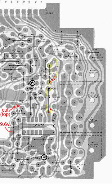
Short the trace from IC401 Pin 15 to the trace that runs next to it. (See figure below)
Cut keyed 9.6v trace as shown below.
Jumper from marked point to constant 9.6v
(The above procedure will stop frequency drift by keeping the first stages of the transmitter running continuously.)
Install a KXN-1019B Element on your frequency.
You should now be true FM'ing with the advantages of peak limiting, and BPF'ing.
Repeaters that don't
de-emphasize the receiver audio:
If "flat audio" throughput is going to be conveyed through the repeater,
there is no need for the exciter to add its own pre-emphasis, as pre-emphasized
audio has been used throughout the repeater audio path. The exciter
can be modified to use the limiter/filter in the blue blob, but not add
the pre-emphasis or de-emphasis that was needed in the PM scheme.
Since pre-emphasized audio is going to be applied to the blue blob, it
will still do the same job it was intended for. Audio will not need
to be de-emphasized after the processing because the FM modulator doesn't
automatically pre-emphasize it. The transmitted audio will follow
the pre-emphasis slope of the user up to the limit of the Splatter Filter
which is about 2500 Hz. The limiter in the blue blob will still be
functional and will amplitude limit the audio so over deviation doesn't
result. The Splatter Filter is also in the blue limiter chip and
cannot be changed (with individual part substitution) to add audio bandwidth.
If this bandwidth is not acceptable, the internal path/processing can be
bypassed and a better outboard limiter/filter application should be fitted.
Such Audio Processing
can be obtained from a few sources.
Modification Procedure:
Remove the following:
R401 - 330 ohm. (if mic bias is not needed)
C408 - .068 uF.
R412 - 22 K.
C421 - 4.7 uF Electrolytic, (disables PM modulator)
Change the following:
R404 from 5.6 K to a 1 K.
C415 from .33 uF to a jumper wire.
Switch polarity on the 4, 4.7 uF tantalum caps that feed the modulation pin.
Jump between the wiper of the IDC pot and the modulation pin bus.
Install a KXN-1019B Element on your frequency.
You should now be true FM'ing with the advantages of peak limiting,
and BPF'ing.
HTML Copyright September 19 2002, Kevin K. Custer
All Rights Reserved.