Background:
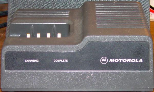
The NTN4633B is the 120V, 50 / 60 Hz rapid charger designed for
the HT600, HT800, MT1000 and similar series radios. The NTN4634 is the same
charger factory wired for 220 / 240V, 50/60 Hz (the only difference
is the plug on the AC line cord and a power transformer - swapped from
120v 60Hz to 240v 50 hz). Both units can charge several sizes and capacities
of Nickel-Cadmium (NiCd) batteries ranging fom 600mAh to 1.2Ah or even
higher. A resistor that is inside the battery pack controls the charging
current. One characteristic of NiCd batteries is that after a pack is
fully charged any additional charging current gets dissipated as heat.
The charger takes advantage of that characteristic with a thermistor mounted
inside the battery pack sensing the rising temperature and the change in
resistance switches the charger into a trickle-charge mode. The batteries
should be removed within a few hours of going to this low charge rate. If
left in too long, the trickle current can cause the batteries to heat up
and shorten their life.
An Motorola official field modification is presented here, along with
pictures showing the locations of the components that need to be removed
or changed. This procedure brings a "B" version charger up to
the current production "C" version. For those of you who need
to know why something is being done, small schematic sections are also
provided.
Note from Mike Burgess G7HID via an email to WA6ILQ:
This modification is also valid (and works well) on the model ELN1040B
(240V, 50 / 60 Hz with Euro plug) and the ELN1041B (240V, 50 / 60 Hz
with UK plug) chargers.
The "Current" Problems:
- The unit overcharges batteries with about 72 milliamps
when in the trickle-charge mode.
- If power fails and returns with a battery in the charger,
it will restart the rapid-charge cycle.
Will Martin KA6LSD (SK) reported that this last issue was discovered during
Hollywood back lot movie shoots. Tungsten lamps have a very low resistance
when cold. When the director called for "lights" the initial current
surge caused the generator voltage to sag. That momentary low line voltage
would cause all of the handheld chargers to reset from "trickle"
to "rapid charge" mode. This fault "cooked" a large
number of batteries before the cause was discovered.
The Benefits of Doing This Modification:
- The trickle-charge rate will be reduced to a safe 25 milliamps.
- If a battery is already in the charger, it will power up in the trickle-charge mode.
- Battery life will be extended due to lower trickle-charge current and fewer rapid-charge cycles.
- If you remove a fully charged battery and want to trickle charge it only, you can insert it,
pull the power plug, and plug it back in (or modify the charger with a normally closed
pushbutton, more on this further down on this writeup).
Step-by-step Procedure:
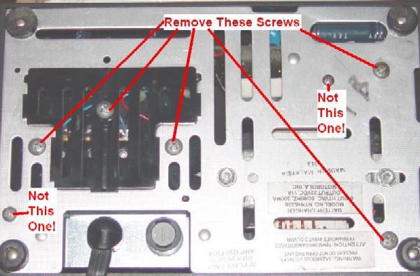
- Remove any radio or battery and unplug the charger.
- With the unit upside down, remove the five large Phillips
screws from the bottom as shown in the photo below.
- Gently but firmly remove the plastic cover from the chassis.
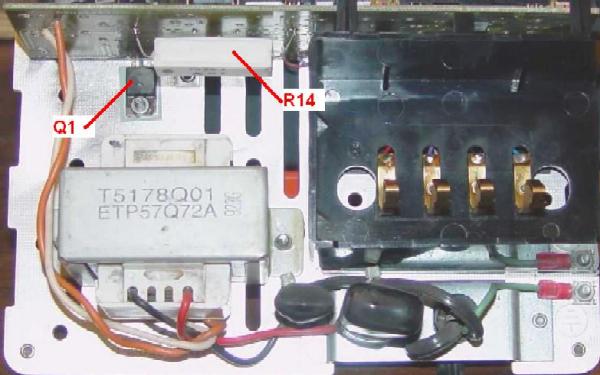
- Now remove the mounting hardware holding Q1 (on the back of the
circuit board) to the chassis. Don't lose the insulators. See the
photo under step 13 below.
- Remove the small Phillips screw holding the circuit board at its bottom
edge near Q1 to the chassis bracket. The board and charger contact
assembly may now be removed together.
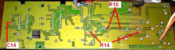
- Unsolder R14, a big 7-watt, 2 ohm ceramic resistor on the back of
the circuit board. This gives you access to R10 in the next step. See
photo below for component locations.
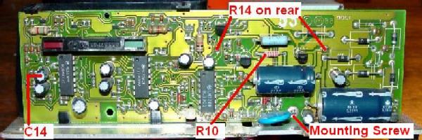
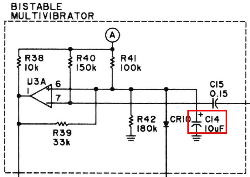
- Remove R10, a 22-ohm resistor. Refer to schematic below for the
electrical location.
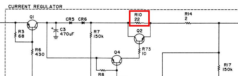
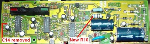
- Install a new 62 ohm, 1/2 or 1 watt resistor in place of
R10. This changes the trickle charge rate. See photo below
for the component hole locations on the back of the circuit
board.
- Reinstall R14 on the back of the circuit board. Position it
as far away as possible from the board, or anything else, to
improve ventilation.
- Unclip the top of the circuit board from the charger contact
assembly. Remove C14, the upper 10 microFarad capacitor near the
left edge of the circuit board. Removing this capacitor prevents the
unit from powering up in the rapid charge mode. See photo below
for the completed modifications.
Refer to schematic below for the electrical location.
Make sure there are no solder bridges or other residue remaining. Clip
the charger contact assembly back onto the circuit board.
- Clean Q1 and the chassis area where it mounts, and apply new
heat sink compound. Make sure there's an insulator between Q1 and
the chassis.
- Remount the circuit board to the chassis bracket with the
small Phillips screw.
- Make sure Q1 is lying flat on the chassis. Then reinstall its
mounting hardware. Make sure there's an insulator between the
screw and the tab of Q1. See photo below of the complete unit.
- Carefully line up the four charger contact fingers into
their slots and replace the cover onto the charger base.
- Install the five large Phillips screws into the bottom of
the charger.
- Note on the bottom of the charger, perhaps with a Sharpie
pen "Field upgraded to version C" and the date for the next guy
that works on it.
Checking The Results:
- Verify that the charger is unplugged from the AC and insert
a battery into the charger.
- Plug the charger into an energized AC power source.
- Verify that the COMPLETE (green) LED lights up, indicating that
the unit is in its trickle-charge mode. You should measure about
50-60 millivolts across R14, which equals 25-30 milliamps.
- Remove and reinsert the battery.
- Verify that the CHARGING (red) LED lights up, indicating that the
unit is in its rapid-charge mode. You should measure about 1.5-2.4
volts across R14, which equals 750-1200 milliamps. A resistor in the
battery pack ultimately controls this current. Larger packs can be
charged with more current.
- If power is interrupted with a battery in the charger, it will come back
on in the trickle-charge mode. Batteries may be left in the charger for up to
24 hours in the COMPLETE mode without harm.
Additional Information:
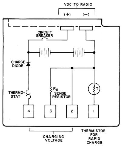
Here's a typical HT600 / MT1000 battery schematic. RR
(Sense Resistor) is used to select the rapid charge current. It has typical values of 3 k
or 5 k ohms. The thermistor on pin 1 is around 10 k ohms at room
temperature and drops to about 5 k ohms when the pack is fully charged.
Notes from Mike WA6ILQ:
1) Above is the schematic of a typical
HT600 / HT800 / MT1000 battery. The
charger connects to the bottom four contacts, and the radio to the
upper two. The circuit breaker at the top (not present in all battery
packs) prevents a defective (shorted) radio from damaging the
battery, or against the time when you put a spare battery nose down
into your pocket on top of your keyring. The "charge diode" at the
bottom prevents damaging or overheating the battery if you
accidentally short the charging contacts, perhaps by inserting
the radio in your pants pocket on top of your keyring... been
there, done that on an older HT200 radio that didn't have the
diode (or if it did, it was shorted)... The "sense resistor"
connected to pin 3 (labeled "Rr") is the one mentioned in the
"Background" text above that determines the actual charging
current. The thermistor conected to pin 1 is the sensor that
controls the switchover from full charge current to trickle charge,
with the thermostat on pin 4 used as backup. The
thermostat is an actual mechanical switching device that is
normally closed when not activated (i.e. when cold). The
thermistor and the thermostat are carefully positioned
inside the battery pack so that they are physically touching
the battery cells and can therefore get an accurate reading
of the current cell temperature.
2) One of the bullet points above mentions "If you remove a
fully charged battery and want to trickle charge it only, you can
insert it, pull the power plug, and plug it back in."
Will Martin KA6LSD (SK) reported that he modified a large number of
chargers with a normally closed pushbotton in series with the power
transformer primary. The chargers were labeled on the top with a note
that to force a trickle charge to press and hold the button while inserting
the battery into the charger.
Acknowledgements and Credits:
Circuit information for the NTN4633 / NTN4634 charger
was obtained from Motorola's official service manuals and service bulletins
(6881079E24 dated 9/1988). Manual 6881108C47 dated 1991 also covers
this charger.
The battery schematic came from the HT600 manual, 6881065C75,
which contains user instructions, maintenance, schematics, etc.
All Motorola part or model numbers (NTN..., NLN..., etc) are
the property (possibly copyrights/trademarks) of Motorola, Inc.
Will Martin KA6LSD (SK) provided considerable information via
Mike Morris WA6ILQ. Will passed at age 81 in January of 2024.
Mike Morris WA6ILQ of the Repeater-Builder web site staff deserves
credit for converting my original Microsoft Word file to clean HTML and
resizing all the pictures and images to make it all look real nice.
Contact Information:
The author can be contacted at: his-callsign [ at ] comcast [ dot ] net.
The page maintainer can be contacted by way of the maintainer link at the top of the page.
Back to the top of the page
Up one level (Genesis index)
Up two levels (Motorola index)
Go to the Home page
Article text and all photos Copyright © 2005 by Robert W. Meister, WA1MIK (SK).
Artistic layout and hand-coded HTML © Copyright 2005 and date of last update
by Mike Morris WA6ILQ.
This web page, this web site, and the information presented in and on its pages is ©
Copyrighted 1995 and (date of last update) by Kevin Custer W3KKC and multiple originating
authors.