Up two levels (Moto index)
Go to the Home page
By Robert Meister WA1MIK

|
Up one level (Genesis index) Up two levels (Moto index) Go to the Home page |
Modifying the Genesis Rapid Battery Charger For Use With NiMH Packs By Robert Meister WA1MIK |
|
Background:
The NTN4633B is the 120V 50 / 60 Hz rapid charger designed for the HT600, HT800, MT1000 and similar radios. The NTN4634 is the same charger factory wired for 220 / 240V, 50 / 60 Hz (the only difference is the plug on the AC line cord and the power transformer - swapped from 120v 60Hz to 240v 50 hz). European models ELN1040B and ELN1041B are identical to the above models except they are both 220 / 240V, 50 Hz and have power plugs appropriate for the locality. There are also multi-pocket gang chargers that have the same circuitry in them, one for each battery pocket. All of these can charge several sizes and capacities of Nickel-Cadmium (NiCd)batteries ranging from 600mAh to about 1200mAh. A resistor inside the battery pack tells the charger circuitry how much current to use during rapid (high-current) charging. These chargers were designed for Nickel-Cadmium (NiCd) cells only.
There are Genesis-series chargers: NTN5538A (120V/60Hz) and NTN5539A (240V/50Hz) that seem to be almost identical. Eric WB6FLY reports just one component difference in the schematics between these and the NTN4633/4634 chargers.
NiCd batteries have a "memory" effect, which means if you don't fully discharge the pack during use, it won't charge all the way to maximum capacity next time. The less you discharge it, the less it charges back to. Eventually the pack will not hold a charge for more than a few minutes or one or more cells will short out or open. This phenomenon is now called "voltage depression" but the results are similar.
Nickel-Metal-Hydride batteries are a more modern technology that supposedly does not have the same memory effect as NiCds. You don't have to fully discharge them before charging them again to full capacity. Unfortunately, there are significant differences in the way the batteries respond to charging, and many NiCd chargers will not charge NiMH batteries properly, and the units described here are no exception.
One characteristic of NiCd and NiMH batteries is that after a pack is fully charged any additional charging current gets dissipated as heat. The charger takes advantage of that characteristic with a thermistor in the pack sensing the rising temperature and switches the charger to a trickle-charge mode. The batteries should be removed within a few hours of going to this low charge rate. If left in too long, the trickle current can cause the batteries to heat up and shorten their life. The desktop charger circuitry is designed to slow-charge the battery if it's lower than 8 degrees or higher than 41 degrees Celsius. Between those two ranges, the pack will be rapid-charged at up to 800 mA. When the temperature rises to 41C, the charger switches to trickle-charging mode.
The Battery Pack:
The various batteries that work with HT600, HT800, and MT1000 radios, all have the same terminals: two on top that fit the bottom of the radio, and four on the back that mate with contacts in the base of the charger. The following is a generic schematic of the battery used in the HT600 radio:
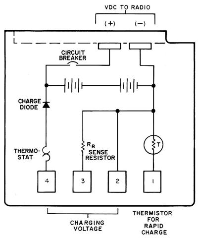
Not all packs have the circuit breaker in series with the positive terminal. Pin 2 is the negative charging reference point. Charging current is fed into pin 4. The resistor at pin 3 is about 3.3k for high-capacity packs which can charge at up to 800mA, or 5.6k for medium-capacity packs, which can charge at up to 500mA. The trickle charge current is also adjusted according to the value of this resistor.
Pin 1 connects to a thermistor that senses the temperature of the pack. As the pack gets hotter, the resistance from pin 1 to pin 2 decreases. When it gets to a specific level, the charger will terminate the rapid-charge mode and switch to trickle rate.
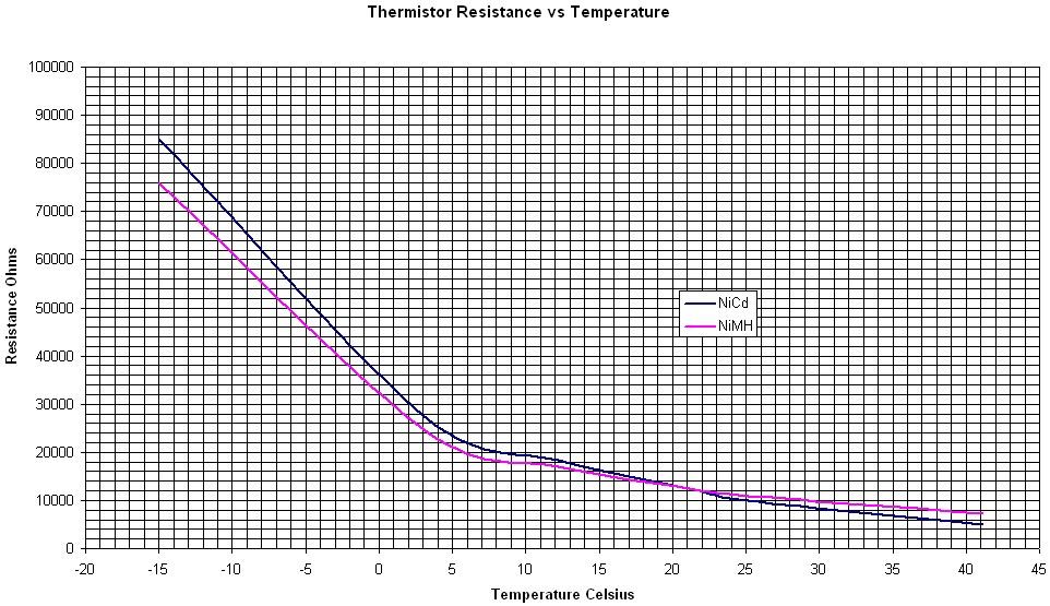
Thermistors are non-linear devices. There are several logarithmic equations that describe the resistance vs. temperature; search the Web if you want more information. The resistance may change by 5000 ohms per degree around -15C, whereas it only changes by 250 ohms per degree around 30C. The graph of this performance is shown below with linear scales. The change in slope around 10C is probably exaggerated due to the granularity of the input data.
Note that thermistors used by different manufacturers will probably have different characteristics. Therefore, even a NiCd pack could be over-charged or damaged by overheating. If your batteries come out the charger more than slightly warm, you may wish to measure the thermistor and adjust R51 accordingly.
All of the battery packs that are used with these chargers are hermetically sealed. If you could open them, you could change the thermistor to one that has the right resistance when hot. Other manufacturers of battery packs and chargers use packs that can be opened, allowing the owner to replace the individual cells. Some also use microswitches to sense the pack's capacity and/or charging rate.
The Thermistor Equation:
Thermistors are most often characterized by using the Steinhart-Hart equation. You can look this up on the web. Basically it takes the resistance and four parameters and comes out with a temperature value. This could be twisted around to give the resistance based on temperature. I'm not a mathematician; maybe I'll ask someone who is.
Anyway, here's one equation that will calculate the temperature value given the resistance and four parameters:
                              1
TEMP = -------------------------------------------------
       a + b * ln(Rth) + c * (ln(Rth))2 + d * (ln(Rth))3
where TEMP is temperature in degrees Kelvin, a, b, c, and d are constants, and Rth is the resistance of the thermistor. For practical reasons, the "c" constant is usually very small or zero, thus the equation can be reduced (and inverted) to:
  1
---- = a + b * ln(Rth) + d * (ln(Rth))3
TEMP
Circuit Analysis:
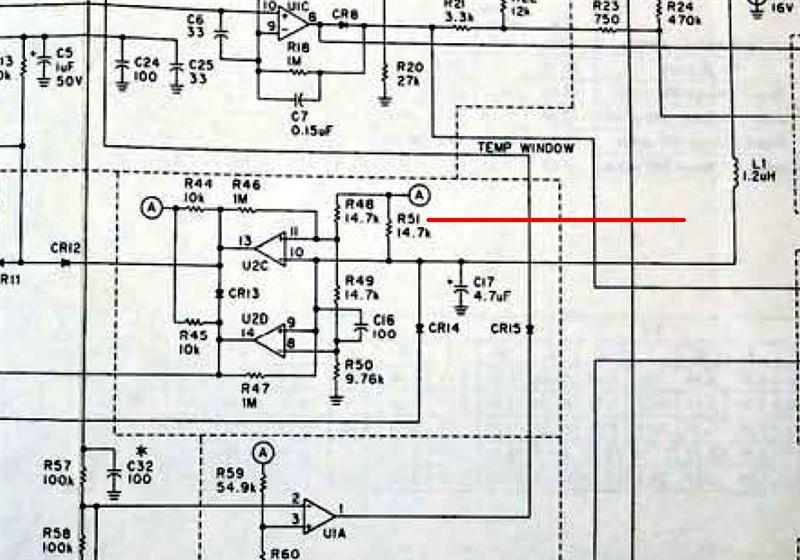
The schematic diagram below shows the part of the circuit that determines the charging mode based on the temperature.
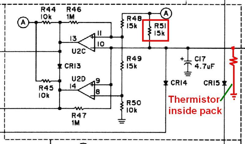
This part of the circuit is called the "TEMP WINDOW". The thermistor, which is located inside the attery pack, comes in at the right side (shown in red as a resistor to ground) and pulls U2D pin 9 and U2C pin 10 to ground. This forms a voltage divider along with R51, which pulls the thermistor up to a source of 12VDC. The voltage at the mid-point (VT, thermistor voltage) is defined by the following equation:
                Rth                  Rth
VT = 12.0 * ----------- = 12.0 * -----------
            (Rth + R51)          (Rth + 15k)
At 41C, when Rth = 5000 ohms, the resulting 3.00 volts is 0.25 times the 12V supply:
                5k
VT = 12.0 * ---------- = 3.00V
            (5k + 15k)
U2C and U2D form a window that operates at two thresholds: temperature above or below 8C (cold), and temperature above or below 41C (hot).
The cold voltage (VC) on U2C pin 11 is determined by R48, R49, and R50, according to this equation:
               (R49 + R50)             25k
VC = 12.0 * ----------------- = 12.0 * --- = 7.25V
            (R48 + R49 + R50)          40k
The output of U2C pin 13 will be low as long as VT is higher than VC, or if the pack is colder than 8C. This keeps the charger in trickle mode. When the pack warms up, U2C pin 13 will go high and rapid charging will commence. If the thermistor is above 25k, the temperature must be below 8C. Note that when Rth = 25k, the VT and VC equations are the same, so now we know the low temperature threshold values.
A similar operation happens with the high temperature half of the circuit. The hot voltage (VH) on U2D pin 8 is determined by R48, R49, and R50, according to this equation:
                   R50                 10k
VH = 12.0 * ----------------- = 12.0 * --- = 3.00V
            (R48 + R49 + R50)          40k
The output of U2D pin 14 will be high as long as VT is higher than VH, or if the pack is cooler than 41C. This lets the charger operate in rapid mode. When the pack warms up, U2D pin 9 goes lower than U2D pin 8, and the charger terminates rapid-charge mode. When Rth = 5k, the VT equation has the same ratio as the VH equation, and the resulting voltage is 3.00V.
The important voltages and thermistor resistance values are given below for typical NiCd and NiMH battery packs. Note the red cell is the problem condition where the pack continues to rapid-charge even after it gets way too hot:
| Meas Pt. |
NiCd Pack, R51=15k | NiMH Pack, R51=15k | ||||
|---|---|---|---|---|---|---|
| <8C | 8-41C | >41C | <8C | 8-41C | >41C | |
| Rth | >=25k | 5-25k | <=5k | >=25k | 7-25k | <=7k |
| VT | >7.25 | 3.00-7.25 | <3.00 | >7.25 | 3.82-7.25 | <3.82 |
| U2D | High | High | Low | High | High | High |
| U2C | Low | High | High | Low | High | High |
| Chg | Trickle | Rapid | Trickle | Trickle | Rapid | Rapid* |
Battery Charging Analysis:
I placed a discharged NiCd pack into the charger and monitored the temperature of the pack with a hand-held infrared thermometer. Yes, I realize that the pack was probably warmer internally than what I measured, but without destroying a pack, this was the best I could do. I also monitored the voltage at U2C pin 10 (VT) and recorded both values. As the pack neared charge-complete and the temperature approached 41C, the VT voltage was dropping at a rate of about 0.003 volts per second. As soon as it dipped below 3.0V, the "charge complete" LED turned on. I removed the pack from the charger and measured the thermistor resistance at that point.
I performed a similar test with a slightly discharged NiMH pack, except I kept a closer watch on the temperature. As soon as it exceeded 41C, I noted the VT voltage, removed the pack from the charger, and immediately measured the thermistor resistance. These operations gave me the final thermistor value.
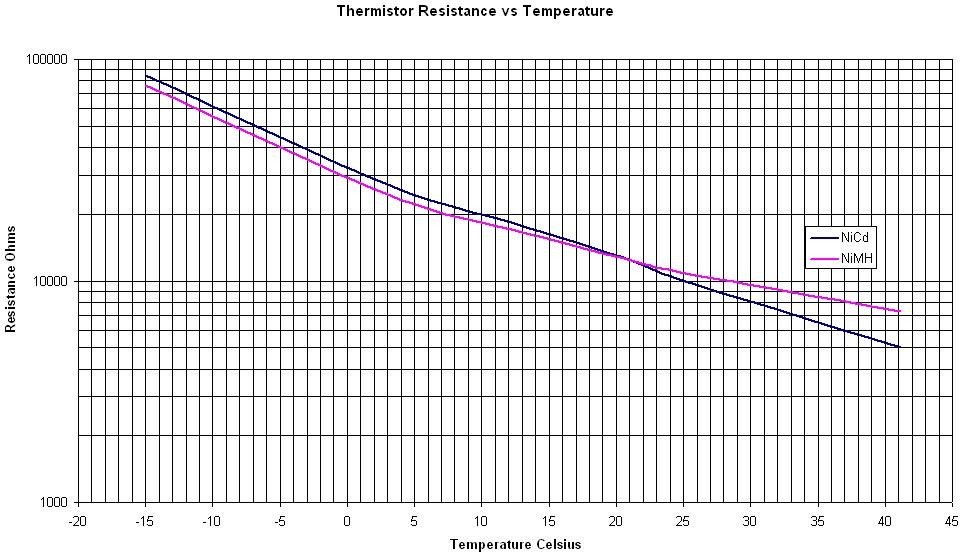
I also put these same packs into my refrigerator for 3 hours, then removed each one and measured the thermistor resistance. I put them into the freezer for another three hours and again measured each pack. This gave me values below room temperature. All of these points were put into the graph below, which has a logarithmic vertical scale. This tends to straighten out the curves, but even so, they're still not linear, and never will be.
Why Does The NiMH Pack Get Overcharged:
That's one of the $64 questions. It all has to do with the thermistor characteristics used in the battery packs.
Looking at the graph, you can see that at 41C the resistance of the NiCd pack gets down to that magic value of 5000 ohms. This satisfies the VT = VH values above. Unfortunately, the NiMH pack only gets down to about 7300 ohms at the same temperature. The change in resistance is non-linear, so the pack has to get a lot hotter before the thermistor resistance comes down to 5000 ohms so the charger completes its cycle. The first time I charged this pack, I left it in the charger for three hours and it still never finished charging. When I removed it, I almost got burned. I do know that there are parts inside the charger that reach 65C, and the NiMH pack wasn't far behind. The resistance never got down to 5000 ohms. I don't want to repeat that experience, as the pack will definitely be damaged by repeatedly overheating it. So the charger merrily cooks the battery waiting for the thermistor to come down to 5000 ohms, which never happened with my pack.
The thermistor in the NiMH pack that I bought has the same resistance value as the NiCd pack at room temperature, and nearly the same value when cooler, but the change in value as the temperature increases does not match the thermistor in the NiCd pack. Since the charger is depending on the thermistor resistance to be 5000 ohms at 41C, the slight difference in this characteristic affect the shut-off time and final charging capacity.
There are some NiMH batteries being sold that claim to be chargeable in any Motorola charger that works with NiCds. It's possible that the manufacturers have selected a different (and better) thermistor such that the charger sees the same resistance at 41C as it got with NiCds. You should let your NiMH pack fully charge one time, then measure its temperature. If the charger completes and the pack is around 40C (slightly warm), then you can leave things alone. If the pack is hotter (more than 45C), then you should make the modification shown in this article.
How Can This Be Fixed:
That's the other $64 question. Actually, it's fairly simple, but it seems to depend on the thermistor used in the battery pack you want to charge. On mine, the resistance reached about 7300 ohms when the pack was at 41C. The VT voltage must equal the VH voltage for the charger to complete its rapid-charge phase.
Since the VH equation reduces to a ratio of 0.25, we need values in the VT equation that match it. This means that R51 must be three times the value of Rth. The stock charger has a 15k resistor here, and the NiCd pack's thermistor resistance is 5k ohms at 41C. The ratio is just where we want it. Now, with the NiMH pack's thermistor resistance of 7.3k ohms at 41C, R51 must be changed to 22k ohms. If you plug the numbers into the VT equation, you find that the ratio is now 0.2491 - close enough for me.
                7.3k
VT = 12.0 * ------------ = 2.99V
            (7.3k + 22k)
The result is that the battery will complete its charge at just a bit under 41C; better safe than sorry. The following table shows the charging parameters with R51 at 15k and 22k. Note that the pack now completes its rapid-charge cycle like it should, as noted by the green cell:
| Meas Pt. |
NiMH Pack, R51=15k | NiMH Pack, R51=22k | ||||
|---|---|---|---|---|---|---|
| <8C | 8-41C | >41C | <8C | 8-41C | >41C | |
| Rth | >=25k | 7-25k | <=7k | >=25k | 7-25k | <=7k |
| VT | >7.25 | 3.82-7.25 | <3.82 | >7.25 | 3.00-7.25 | <3.00 |
| U2D | High | High | High | High | High | Low |
| U2C | Low | High | High | Low | High | High |
| Chg | Trickle | Rapid | Rapid* | Trickle | Rapid | Trickle# |
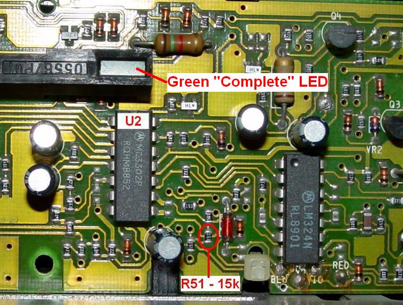
R51 is a surface-mount resistor that can be seen in the photo below. There's plenty of room to insert a regular leaded resistor at various points on the circuit board.
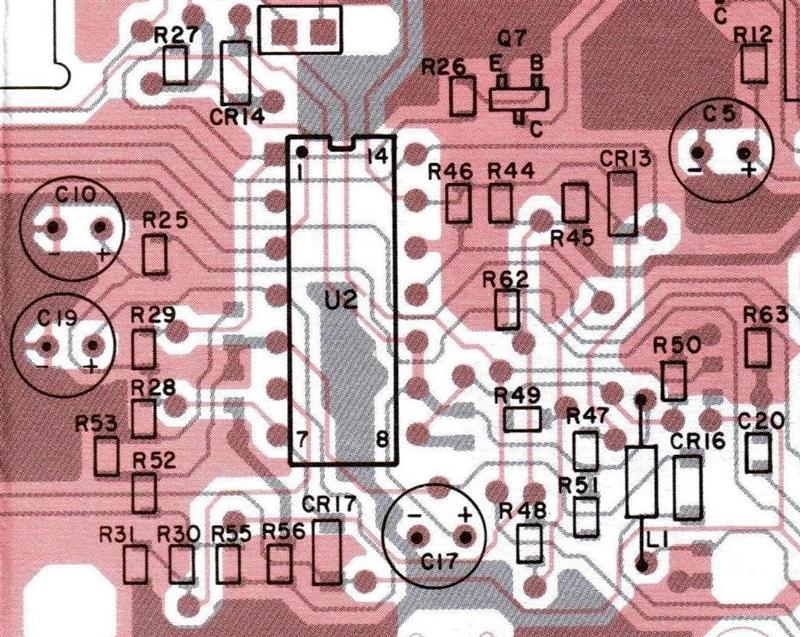
If you need an alternate location, refer to the X-ray view of that area of the board, shown below. R51 is below and to the right of U2. One suggestion is to solder one end to U2 pin 3 (+12V) and the other end to U2 pin 9 or 10.
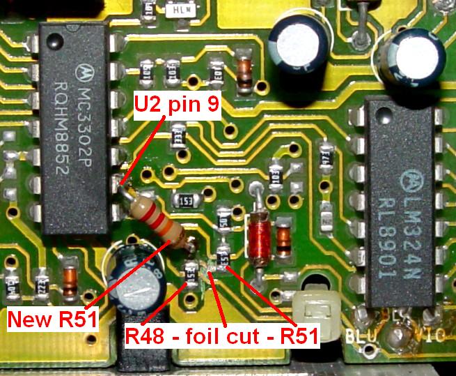
I chose to make a small cut in the foil trace running from the lower end of R51 to the upper end of R48. I then soldered a 22k resistor from U2 pin 9 to the feed-through hole at the top of R48. The photo below shows the cut and the installed resistor:
Once you've made this modification, the charger will no longer fully rapid charge NiCd packs. The rapid charge cycle will terminate when the pack gets to about 32C, way before the pack is 90% charged. You can leave it in trickle-charge mode for another eight hours to complete the charging cycle.
If you DO modify the charger in this way, it would be useful to attach a big note on the front indicating the charger will only properly charge NiMH battery packs. This may deter people from expecting it to charge NiCd packs.
You could add a switch to select the appropriate value of R51 for charging NiCd packs (R51=15k) or NiMH (R51=22k) packs, however mounting such a switch through the top cover of the charger is not trivial. We leave that as an exercise for the student.
The NTN4633A charger uses leaded components, rather than surface-mount. The same component (R51) can be changed from 14.7k (instead of 15k) to 22k. The location is shown in the X-ray view below. No foil cuts are necessary. You can easily lift either end of R51 (or remove it entirely) and solder a new resistor into the circuit.
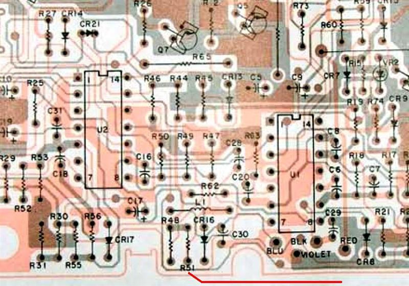
For completeness, here's a segment of the schematic for this version.
Verifying Your Results:
Unfortunately, each battery pack manufacturer can use his/her own thermistor, so the resistance value at 41C can be almost anything. All you can do is charge your NiMH battery while checking its temperature, and when it reaches 41C, remove it, measure the thermistor resistance, and choose a different value for R51 that's three times the resistance in the pack. That will balance the VT equation. You should then be able to let the pack cool off for an hour, put it back into the charger, and the rapid-charge cycle should complete with the battery at or near 41C. The pack can then sit in the charger for a few more hours at the trickle-charge rate to top it off. Do NOT leave a NiMH pack charging for more than a few hours.
After replacing R51, I put a room-temperature (25C) NiMH pack into the charger and measured the voltage at U2 pin 9 (VT): it was exactly 4.00 volts. I removed the pack and measured the resistance of the thermistor: it was 11000 ohms. So the circuit does seem to operate the way the theory says. That's a good thing.
Selecting NiCd or NiMH Charging Rates:
If you have packs of each type, you probably would like the charger to select the proper charging rate automatically. I've switched from NiCd to NiMH packs so I'm content with permanently changing the resistor and marking the charger as such.
Unfortunately, there are no unused terminals on the battery packs, so you can't tell just from plugging a pack into the charger. You could possibly mount a small microswitch in the battery well and either drill a small hole or file a notch in the NiMH pack so the switch could detect which pack was inserted. Problems with this include violating the hermetic seal around the pack, and having an ugly hole or notch somewhere on the pack.
You might be able to find an old reflective write-protect tab, the kind they used to use with 5-1/4 inch floppy disks, and attach that to the bottom or side of the pack, then use some kind of LED and light sensor to detect the reflection when the pack is installed. Even a small piece of aluminum foil glued to the side of the pack would work. Appropriate circuitry could then select the proper value for R51.
Some silver conductive ink could be used to mark a spot on the packs. This could be sensed with a pair of contacts to select the proper value for R51.
Another method would involve user-intervention - pushing a switch - to select the proper charging conditions. One method would be a momentary push-button switch that would activate a relay, latching itself on while a battery is present and selecting the appropriate value for R51. When the battery is removed, the relay drops out and is ready for the next cycle. You'd only need to press it for one kind of pack, whichever one you charge less often. It would make sense to leave R51 set at 22k, so even if you forget to push the button, NiCd packs would just complete before getting fully charged, and not do any harm to either pack due to overheating. This would be a fail-safe mode.
You could also use a toggle switch and hard-wire it to R51. Drill a hole almost anywhere in the outer case, mount the switch, label it, and use some kind of connector to allow you to remove the cover without the wires getting in the way. Use a 22k resistor for R51, then wire the switch to add a 47k in parallel with it when you want to charge a NiCd pack. This drops the effective resistance value back down to 15k. The charger will still operate at the NiMH rate with the cover off and/or the switch disconnected. The only difficulty with this method is that you must be sure to set the toggle switch any time you insert a battery into the charger. However, a DPDT center-off toggle switch would allow you to choose the pack type - NiCd or NiMH - and also turn the AC power off when the charger is not in use. As long as you set the switch properly for the pack you wish to charge, it should work fine. You can safely undercharge a NiCd pack, but overcharging a NiMH pack will severely reduce its useful life.
Epilog:
After I finished modifying my charger, I naturally wanted to test it with a NiMH pack and make sure the rapid charge cycle properly terminates. Well, for some reason, every pack I had was causing both charger LEDs to flash on and off. The manual said this condition was caused by a shorted cell or an open battery pack. Since all the packs had just been charged a week earlier, and the NiMH packs were only a month old, I decided that there was some other reason. So out came the full schematic and a voltmeter.
To make a long story short, I found a bad solder joint on transistor Q1. The circuitry was attempting to put out lots of current and heating up a 430 ohm resistor in the process. I ended up replacing Q1 and I put in a 2 watt 430 ohm resistor. After the new parts were installed, I put my NiMH battery pack in the charger and monitored the thermistor voltage. It started at 4.0V at room temperature, and after 80 minutes, the voltage got down to 2.99V and the red Charging LED turned off and the green Completed LED turned on. At this point, I removed the pack and measured 7300 ohms across the thermistor. The pack was warm but not at all hot. Interestingly, a few minutes later the thermistor resistance had dropped to 7000 ohms, indicating there's some thermal lag between the pack's cells and the thermistor.
I have not tried charging one of my NiCd packs yet, but I suspect it will just stop rapid charging when the thermistor resistance drops to 7300 ohms.
Update:
Another set of NiMH batteries seemed to charge properly but the cycle always ended after 20 minutes. The packs were barely warm. I ended up adding a 100k resistor in parallel with the 22k resistor, dropping the overall resistance to about 18k. After use, the packs now charge for about an hour and are noticeably warm to the touch. I also leave them in the charger, trickling, for another few hours. When I remove them, they're slightly above room temperature, but they seem to let the radio operate a lot longer.
Acknowledgements and Credits:
Circuit information for the NTN4633 / NTN4634 charger was obtained from Motorola's official service manuals and service bulletins (6881079E24 dated 9/1988). Manual 6881108C47 dated 1991 also covers this charger.
The battery schematic came from the HT600 manual, 6881065C75, which contains user instructions, maintenance, schematics, etc.
All Motorola part or model numbers (NTN...., NLN...., etc) are the property (possibly copyrights/trademarks) of Motorola, Inc.
All photos and graphs were taken or generated by the author and are copyright by him.
Ed KE4ZNU provided some useful battery and charger information in the April 2007 issue of Circuit Cellar magazine. He also reviewed this article.
Eric K1NUN confirmed that the NTN4633A does indeed use leaded components.
Contact Information:
The author can be contacted at: his-callsign [ at ] comcast [ dot ] net.
Back to the top of the page
Up one level (Genesis index)
Up two levels (Moto index)
Go to the Home page
Article text, layout, hand-coded HTML Copyright © 2007 by Robert W. Meister WA1MIK.
This web page, this web site, the information presented in and on its pages and in these modifications and conversions is © Copyrighted 1995 and (date of last update) by Kevin Custer W3KKC and multiple originating authors. All Rights Reserved, including that of paper and web publication elsewhere.