Up two levels (Moto index)
Back to Home
Radio Information,
Notes, and Tips
-Common Section-
By Robert W. Meister WA1MIK

|
Up one level (GTX index) Up two levels (Moto index) Back to Home |
GTX 900 MHz Radio Information, Notes, and Tips -Common Section- By Robert W. Meister WA1MIK |
|
With the growing interest in FM and repeaters on the 900 MHz amateur frequencies, Motorola GTX radios are becoming the hot item due to their size, cost, ease of operation, and simple conversion process (you don't even need to open the case of the radio). Here's a collection of useful items about these beauties.
This was originally one very big article. It has been split into three pieces to better address the needs of the viewers. Information pertinent to all radios will be found here. There is a slight duplication across the three articles, which was necessary for clarity.
Channels and Frequency ranges:
The GTX mobile radios, and the GTX handhelds with the display and keypad, provide 10 conventional channels, plus 10 trunking channels and 8 talk groups; only the conventional channels are usable by amateurs. The handhelds without keypads provide 4 conventional channels, plus 4 trunking channels with 3 talk groups each. The programming software controls these values and it can be altered.
There must always be at least one trunking channel programmed into all GTX radios; the RSS will let you delete all but one; it's just one of the facts of life - live with it. You can't make any trunking channels inactive on PrivacyPlus models, however on LTR radios, you can disable the trunking channel and it won't bother you again.
When you acquire any radio, remember to make a copy of the original code plug and archive it. It's always nice to be able to fall back to something that you know works if you mess things up.
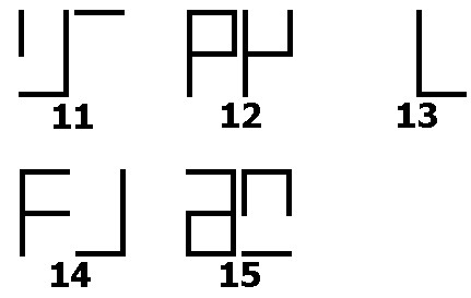
It's interesting that the GTX radios that have an LCD display should be capable of handling channel numbers above 10, but for some reason, they don't. I programmed my PrivacyPlus and a friend's LTR mobile radios with 15 conventional channels to see how they display. I've tried to represent the segments below. I'm sure that if you had even more channels in the radio it would come up with other strange displays. Other models may show different segments, and it could depend on the information in the code plug. Here is a graphical representation of the display for channels 11 through 15:
 |
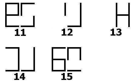 |
| PrivacyPlus mobile radio | LTR mobile radio |
900 MHz GTX radios normally transmit on 896-902 MHz (repeater inputs) and 935-941 MHz (called "talk-around" by Motorola and the commercial two-way world, or "simplex" or "direct" by amateurs). The radios will transmit throughout the 896-941 MHz range but RF output power is inconsistent from frequency to frequency. Values in RSS determine valid frequency ranges.
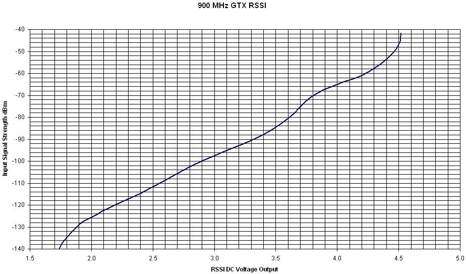
900 MHz GTX radios normally receive 935-941 MHz. The radios will receive well, and within spec, down to around 918 MHz but will be totally deaf by 912 MHz, so a stock GTX mobile will not make a good repeater receiver at 902 MHz, and in fact won't work down there at all (besides, a modified 800 MHz talk-around MaxTrac is much cheaper). The receiver's front-end filters are only so wide, and they will reject 902 MHz signals quite nicely. Most of this sensitivity loss is due to the 6 MHz wide ceramic front end filters tuned to 939 MHz. The receive VCO similarly has limited range and will cease to function if you go down that low. Rick NU7Z has come up with a mod that allows them to work well as repeater receivers. Contact him to find out what he currently charges to convert a radio (nu7z [ at ] aol [ dot ] com). There is no official COR signal available to the user, however the Audio PA Enable signal can be used instead. Unfortunately this line goes active any time the radio makes a beep sound, as when a button is pressed or the radio is turned on, but that's better than nothing. The PL/DPL is decoded internally by the microprocessor, which makes the decision whether to un-squelch the receiver or not. The graph below shows the input signal level required for a consistent Received Signal Strength Indicator (RSSI) voltage (think of the RSSI numbers as an analog S-meter voltage). Click on it for a larger image.
Modifications Required for Amateur Use:
All GTX 900 MHz radios can transmit on the 902-903 MHz repeater input frequencies and receive the 927-928 MHz repeater output frequencies with no hardware modifications at all. The RSS limits what frequencies can be programmed into the radio, so the only "mod" required is a software patch that changes the band edge limits in the RSS (see below).
These radios, as-is, aren't suited for working 12 MHz split repeaters or systems running 5 kHz deviation. They have narrow-band filters in the receiver, which makes the distortion quite noticeable above 2.5 kHz input deviation. The receiver will make it down to 920 MHz, but the transmitter may not make it up to 908 MHz.
The programming software limits the radios to the number of channels described above. However, through hex-editing, these numbers can be altered. People commonly increase the number of conventional channels to 15. If you end up with a radio that has more than 10 conventional channels, you will need to similarly modify your copy of the software to match, just to allow you to read the radio. Otherwise you will get error messages from RSS.
900 MHz Manuals and RSS Products:
These items cover the GTX LTR, GTX Privacy Plus, and GTX LCS2000 series of radios on 900 MHz unless otherwise stated. Some of these manuals are available as PDF files; see the main GTX Info page. Some are No Longer Available (NLA) from Motorola.
Programming:
There is nothing adjustable inside the radios. All alignment and settings are done with RSS: output power, deviation, low frequency compensation, frequency warp, and squelch. Power and deviation are aligned at eight frequencies in each of the 895.5 to 902.5 MHz, and 935.5 to 941.5 MHz bands.
One program handles the 800 MHz and 900 MHz GTX mobiles and handhelds, all variations. It does seem to be Windows-friendly, however I have not programmed a radio by running it in anything other than pure MS-DOS. The software permits programming of all conventional and some trunking features, viewing of all trunking controlled parameters, and contains some helpful service aids for troubleshooting purposes. The Motorola GTX Radio Service Software (RSS) Privacy Plus (PP) / LTR currently supports the following model radios:
'Standard' full-featured models. Handhelds have keypad and display.
Model Number Description Band & Power
M11UGD6CB1_N GTX/PP Mobile
800 MHz, 15 watt
M11WGD4CB1_N GTX/PP Mobile
900 MHz, 12 watt
H11UCD6CB1_N GTX/PP Handheld
800 MHz, 3 watt
H11WCD4CB1_N GTX/PP Handheld
900 MHz, 3 watt
M11UGD6CU1_N GTX/LTR Mobile
800 MHz, 15 watt
M11WGD4CU1_N GTX/LTR Mobile
900 MHz, 12 watt
H11UCD6CU1_N GTX/LTR Handheld
800 MHz, 3 watt
H11WCD4CU1_N GTX/LTR Handheld
900 MHz, 3 watt
'Standard' full-featured 'High-Power' mobiles.
Model Number Description Band & Power
M11URD6CB1_N GTX/PP Mobile
800 MHz, 35 watt
M11WRD4CB1_N GTX/PP Mobile
900 MHz, 30 watt
M11URD6CU1_N GTX/LTR Mobile
800 MHz, 35 watt
M11WRD4CU1_N GTX/LTR Mobile
900 MHz, 30 watt
'Basic' model handhelds have no keypad or display.
Model Number Description Band & Power
H11UCC6DB1_N GTX/PP Handheld
800 MHz, 3 watt
H11WCC4DB1_N GTX/PP Handheld
900 MHz, 3 watt
H11UCC6DU1_N GTX/LTR Handheld
800 MHz, 3 watt
H11WCC4DU1_N GTX/LTR Handheld
900 MHz, 3 watt
There are several versions of programming software "out there". As with many other Motorola radios, once you use a newer version of software (such as R04) to program the radio, you can't use an older version (such as R01) to read or write the code plug.
An early version of lab software is also "floating around". This can be used to blank a GTX radio. Any version of RSS can initialize a blank radio, but the process requires that you load an existing, known good, code plug that will be written to the radio. This means that the code plug you use to initialize the radio must have been saved with the same version of software you're now about to use. You can't go downwards in versions. If you wrote to the radio with R04 software, you can only read and write it subsequently with R04 software. If you have a code plug you saved with R01 software, then you can write that back to the radio if you initialize it with R01 software. There is more information about the version incompatibility issue in the RSS article elsewhere on this web site.
You may encounter error E06 if something goes wrong during programming. You should first try writing the code plug again. If that doesn't fix things up, make sure you've saved the code plug to disk, then go into the Service Menu (F2), select Alignment, and choose either Transmit Power or Warp Frequency. Adjust the setting up or down by one value and write it back to the radio with F8. Exit the Service Menu, read the saved code plug from disk, and try writing it to the radio again. If this doesn't fix it, you probably will hae to blank and initialize the radio, a procedure that requires lab software.
Hear-Clear:
Hear-Clear is a noise reduction system based on audio compression and expansion developed by Motorola that is only provided on their 900 MHz systems and equipment. It's probably similar to other manufacturer's techniques. Spectra radios call the circuit a compander. The system looks at the received signal strength and the high frequency noise at the receiver and adjusts the audio response to eliminate most of the flutter, pops, and clicks that are prevalent with motion. The transmitter audio is filtered and compressed to bring low levels up. The receiver applies similar expansion to return the audio to normal levels. This also tends to reduce the high frequency components and a lot of the noise along with it. The audio filtering tends to make the audio sound thin, but most of the energy is now in the normal communications-quality frequency range of about 400 to 2500 Hz. PL and DPL signals are unaffected.
In an all-Motorola repeater environment, Hear-Clear would be enabled on all user radios as well as the repeater. The repeater's receiver will adjust its action based on the signals it hears. The user's radio will adjust its action based on the signal put out by the repeater. Unfortunately, Hear-Clear is only available on 900 MHz products. In MaxTracs, the Hear-Clear component (one hybrid epoxy module) is mounted on the microphone jack circuit board and the 900 MHz logic board enables or disables the circuit on a channel-by-channel basis (configured through RSS). Hear-Clear is either enabled or disabled, and it always affects both receive and transmit audio. The connections to the Hear-Clear module are very simple: Power and ground, RX audio in and out, TX audio in and out, and an enable pin that switches the Hear-Clear function on and off. The hybrid modules are treated as "black boxes" in all the manuals; no documentation of the actual circuitry is shown anywhere.
A repeater without Hear-Clear can still be used. The repeater must pass clean audio and the user radios can have Hear-Clear enabled. Unfortunately, the part of the system that utilizes signal strength will be fooled by the constant strong signal coming from the repeater's transmitter, but the user radios will still benefit from the compression and expansion of the audio signal. Pops and clicks will be noticeably removed. Radios without Hear-Clear can also use the repeater, but the audio will sound strange if a mix of radios is used.
Several 900 MHz repeaters in my local area experimented with it. We ended up using de-emphasized audio from an 800 MHz MaxTrac modified to receive at 902 MHz that feeds a repeater controller that feeds a 927 MHz MaxTrac transmitter's pre-emphasized mike input. The result is relatively flat response. All users have Hear-Clear enabled on their radios for the repeater channels. Audio generated from within the controller (i.e. the IDer, synthesized speech messages, or the autopatch) sounds strange (mushy is the best way to describe it) because it hasn't gone through the same processing that incoming signals (with Hear-Clear) have. If you are going to be controlling a repeater with a DTMF-equipped GTX you may want to program one channel with HC and another identically but without HC, and use the second one to command the repeater. The next generation of repeater controllers will need a Hear Clear pre-processor for the internal audio source(s), and a Hear Clear "front end" for the DTMF decoder.
Modifying the GTX RSS for 900 MHz Amateur Radio Frequencies:
The GTX radios use a Radio Service Software program (RSS) for all programming. The GTX version R04.00.01a release is the latest one as of this writing (December 2007). One of the files included with the package is GTX.MDF, the Model Definition File. This file is 2024 bytes long. You will need a hex (or binary) editor to make changes to this file. I use, and recommend, a program called Hex Workshop by BreakPoint Software Inc.
NOTE: As mentioned above, before you start, make a copy of the original file, perhaps named GTXMDF.OLD, in case you make a mistake when editing it or your changes don't work. In particular, if the checksum is incorrect, the program will not let you do anything to your radio. In that case you can delete your non-working file, make a fresh copy from the backup, and start over. It's better to have a reserve copy that you don't need than to need one you don't have.
The first thing to do when you open GTX.MDF with Hex Workshop is to obtain the checksum of the entire file. You will need to maintain this value after you've made changes to the file. The data in the GTX.MDF file is authenticated by this value. To obtain the checksum, just click on the "Tools" menu and choose the "Generate Checksum" item. Pick the "Checksum (16 Bit)" option, make sure it operates on the entire file, and click "Generate". I get a value of 73F0, but it could be different if your version is not the same as the one I used. Write this number down somewhere.
The GTX.MDF file contains several frequency range entries. The one we're interested in starts at hex address 0290 and contains the following hex data:
0023 C224 0023 3C23 8624 C224 0A00
Each entry consists of several 16-bit numbers in Intel format. This means the byte order is reversed from what seems to make sense. When you see a value like 0A00, you need to flip the bytes in your mind to come up with the more normal value 000A, which is 10 decimal.
The first pair of values represents the frequency range that the RSS displays when working on 900 MHz GTX radios. The second pair of values controls the transmit frequency limits. The third pair of values controls the receive frequency limits. Hex Workshop will automatically display the decimal values of these 16-bit numbers. The decimal values of the data shown above is:
8960 9410 8960 9020 9350 9410 0010
In plain English, this means the radio can operate from 896.0 to 941.0 MHz, the transmitter's range is 896.0 to 902.0 MHz, and the receiver's range is 935.0 to 941.0 MHz. (The last value, 0010, is actually an index number for these entries. Other data in the file will choose band limits by using this reference number.) We can change a few bytes to change the ranges to allow the radio to operate in the amateur part of the band. The transmitter's upper limit will be changed and the receiver's lower limit will be changed. I'm going to make them both cover 896.0 to 941.0 MHz. This will let the radio be programmed to frequencies in the commercial and amateur bands. The necessary changes are shown underlined and in red below, along with the results:
Original Data: 0023 C224 0023 3C23 8624 C224 0A00
Modified Data: 0023 C224 0023 C224 0023 C224 0A00
This changes all the values to (decimal) 8960, 9410, 8960, 9410, 8960, 9410. We only had to change two of the six values. Now save the file. You shouldn't need to create a backup, since you did that step before you started editing the file.
Note that the file address of 0290 (hex) is appropriate for release 4 of the GTX RSS; if you have an older version, the location might be slightly different, but you should be able to find the byte string shown in the "Original Data" above somewhere close to hex address 0290.
After making these two changes, I generated the checksum again. It came out 73F0, just as it was before I edited the file. The checksum after editing MUST BE the same as it was on the unaltered file. It's purely coincidental that it worked out this way. You may now throw away that slip of paper on which you wrote the original checksum value.
The GTX MDF File Structure:
The MDF file has a specific layout, which is known by the RSS program. The beginning of the file is an index area. Once you understand the layout of the index, you can find the other areas with ease. This should allow you to hex-edit other versions of the programming software. Note that other RSS packages have similar file structures but may have more or less areas defined by the index.
This binary file contains six areas. The first area holds index information for the rest of the file and lets the program locate the five other areas following it.
Each index entry consists of three pieces of information:
All of these values are in Intel format. Here's what they are for the R04.00.01a version. All values are hexadecimal except those in parentheses, which are their decimal equivalents:
Index
AddressAddress of
area in MDFLength of
each entryNumber of
entriesWhat the data in
this area consists of
0000 2800 0000
0E00 (14) 1E00 (14)
Options
0008 CC01 0000
0E00 (14) 0400 (04)
Radio Series
0010 0402 0000
0E00 (14) 0E00 (14)
Frequency Ranges
0018 C802 0000
1000 (16) 1300 (19)
Unknown Data
0020 F803 0000
3200 (50) 1400 (20)
Model Parameters
Each 16-bit value has its bytes in what seems to be reversed order, so when you look at this data, you need to switch the bytes in your head; you still need to enter them in reversed order when using Hex Workshop. For example, at address 0010, you see 0402 0000. You can drop the 0000 part, but the 0402 is really interpreted as 0204. This means the frequency range list starts at address 0204 in the MDF file. Each entry is 000E bytes (or 14 decimal) and there are exactly 000E (or 14 decimal) entries in this table. If you notice, the first hex address in the index is 0028, and that's where the Options table starts, immediately after the index area.
The frequency range table consists of seven individual 16-bit (two byte) values, for a total of 14 (000E) bytes long. Each entry consists of the following fields:
Here's the full table as it exists in the MDF file. All values are hexadecimal. Remember that the individual values have their bytes reversed, so the first RSS Low value of E405 should be read by you as 05E4. If you convert this to decimal you'll find that it comes out as 1508; you'll see this in the table of decimal values following this one. Also, the frequency limit values have an implied decimal point between the 3rd and 4th digits, so the 1508 really means 150.8 MHz. If you wanted to change this to 123.4 MHz, you would convert 1234 from decimal to hex (04D2), then enter it in reverse order (D204) into the table with Hex Workshop.
Address
in MDFRSS
LowRSS
HighTrans
LowTrans
HighRecv
LowRecv
HighIndex
Num
0204 E405 5406
E405 5406 E405
5A06 0000
0212 9411 5C12
9411 5C12 9411
5C12 0100
0220 5005 5406
5005 5406 5005
5A06 0200
022E B405 CC06
B405 CC06 B405
CC06 0300
023C BE0F CC10
BE0F CC10 BE0F
CC10 0400
024A 1C11 5C12
1C11 5C12 1C11
5C12 0500
0258 5C12 8813
5C12 8813 5C12
8813 0600
0266 4C13 5014
4C13 5014 4C13
5014 0700
0274 0000 0000
0000 0000 0000
0000 0800
0282 7C1F D421
7C1F 1220 3E21
D421 0900
0290 0023 C224
0023 3C23 8624
C224 0A00
029E E40C 740E
E40C 740E E40C
740E 0B00
02AC 200D 600E
200D 600E 200D
600E 0C00
02BA 600E 6E0F
600E 6E0F 600E
6E0F 0D00
Here's the same table. The Address column is the actual hex address. The limit values are shown as decimal numbers. The Index Number is also a hex value:
Address
in MDFRSS
LowRSS
HighTrans
LowTrans
HighRecv
LowRecv
HighIndex
Num
0204 1508 1620
1508 1620 1508
1626 0000
0212 4500 4700
4500 4700 4500
4700 0001
0220 1360 1620
1360 1620 1360
1626 0002
022E 1460 1740
1460 1740 1460
1740 0003
023C 4030 4300
4030 4300 4030
4300 0004
024A 4380 4700
4380 4700 4380
4700 0005
0258 4700 5000
4700 5000 4700
5000 0006
0266 4940 5200
4940 5200 4940
5200 0007
0274 0000 0000
0000 0000 0000
0000 0008
0282 8060 8660
8060 8210 8510
8660 0009
0290 8960 9410
8960 9020 9350
9410 000A
029E 3300 3700
3300 3700 3300
3700 000B
02AC 3360 3680
3360 3680 3360
3680 000C
02BA 3680 3950
3680 3950 3680
3950 000D
If you look carefully, you'll see the entry at 0290 is the one described in the previous section. As you move the cursor across the hex values in the table, you'll see the decimal values displayed in the lower left section of the screen, if you've got Hex Workshop set up the way I have mine.
The index number is used in the Model Parameters section of the MDF file. You'll find the various radio model numbers in this section, and as this RSS package is for the 800 and 900 MHz radios, all of the entries will specify frequency index 09 or 0A.
See the companion article in this section of the web site for more detailed information.
Acknowledgements and Credits:
Some of the information about hex-editing this file was obtained from Bruce KC7GR and other sources on the web.
MaxTrac, GTX, PL, DPL, Radius, GM300, RSS, "Radio Service Software" and Hear-Clear (and a bunch of other things) are registered trademarks of Motorola, Inc.
Schematics, specifications, and other scanned data sheets came from Motorola manuals and documents. Copyright on these items is retained by Motorola.
Contact Information:
The author can be contacted at: his-callsign [ at ] comcast [ dot ] net.
Back to the top of the page
Up one level (GTX index)
Up two levels (Moto index)
Back to Home
This page originally posted 03-Dec-07.
Article text, photographs, and hand-coded HTML
© Copyright 2007 By Robert W. Meister WA1MIK.
This web page, this web site, the information presented in and on its pages and in these modifications and conversions is © Copyrighted 1995 and (date of last update) by Kevin Custer W3KKC and multiple originating authors. All Rights Reserved, including that of paper and web publication elsewhere.