Up two levels (Moto index)
Back to Home
Radio Information,
Notes, and Tips
-Handheld Section-
By Robert W. Meister WA1MIK

|
Up one level (GTX index) Up two levels (Moto index) Back to Home |
GTX 900 MHz Radio Information, Notes, and Tips -Handheld Section- By Robert W. Meister WA1MIK |
|
 "Basic" handheld Photo by W6JK |
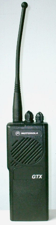
 "Standard" handheld |
 With stubby antenna Photo by XE2DAK |
Model Specifications:
Model Number Charts:
There are GTX handhelds without the display and keypad. These are sometimes called the "basic" model. A typical model number for one of them is H11WCC4DU1AN; the second "C" indicates no display. The 16-position rotary switch on the top of the radio gives you the ability to select one of 12 trunking channels (3 talk groups on each of 4 systems) and 4 conventional channels. The trunking channels are useless to amateurs, so the stock radio is effectively a four-channel radio to a ham. It is possible to hex-edit the RSS to get up to 15 conventional channels on the basic radio. Bruce KC7GR also has hex-edited the RSS to get more conventional channels; see his web page for details on that modification.

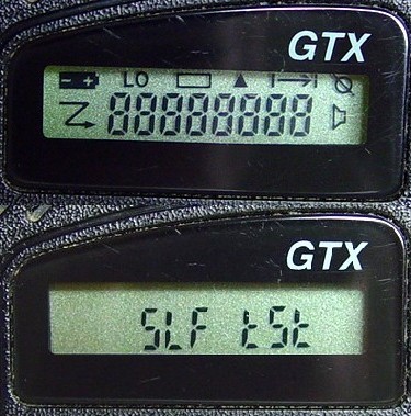
Standard Model Display:
The GTX standard model has an LCD display capable of showing eight seven-segment characters plus eight icons around the outside. All segments and icons will be shown when the radio is first turned on; then the display shows "SLF tSt" (self test), and it finally displays the last used channel number. These first two screens are shown in the photo below:
The various icons, starting at the lower left corner and working clockwise, are:
Programming:
The GTX handheld requires a two-wire cable that connects to a programming foil and ground on the back of the radio. Motorola makes two adapters that fit between the battery and the radio, allowing the battery to still operate the radio. One adapter has a microprocessor inside that can read a code plug and write it to several other radios as a "clone" operation. The other adapter (shown below) does not have this intelligence built-in. Both have a power cord attached but take care not to exceed 7.5 VDC as there is an SCR inside which will fire if the applied voltage exceeds this amount. You can make your own adapter and power the radio externally. There are clones available from various sources. This adapter, also used by the GP300, is HKN9857A (programming cable).
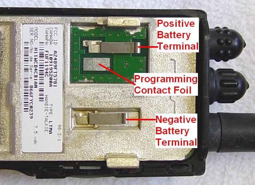
Here's a photo of the back of a radio showing the two battery terminals and the foil that makes contact with the spring-loaded pin on the programming adapter:
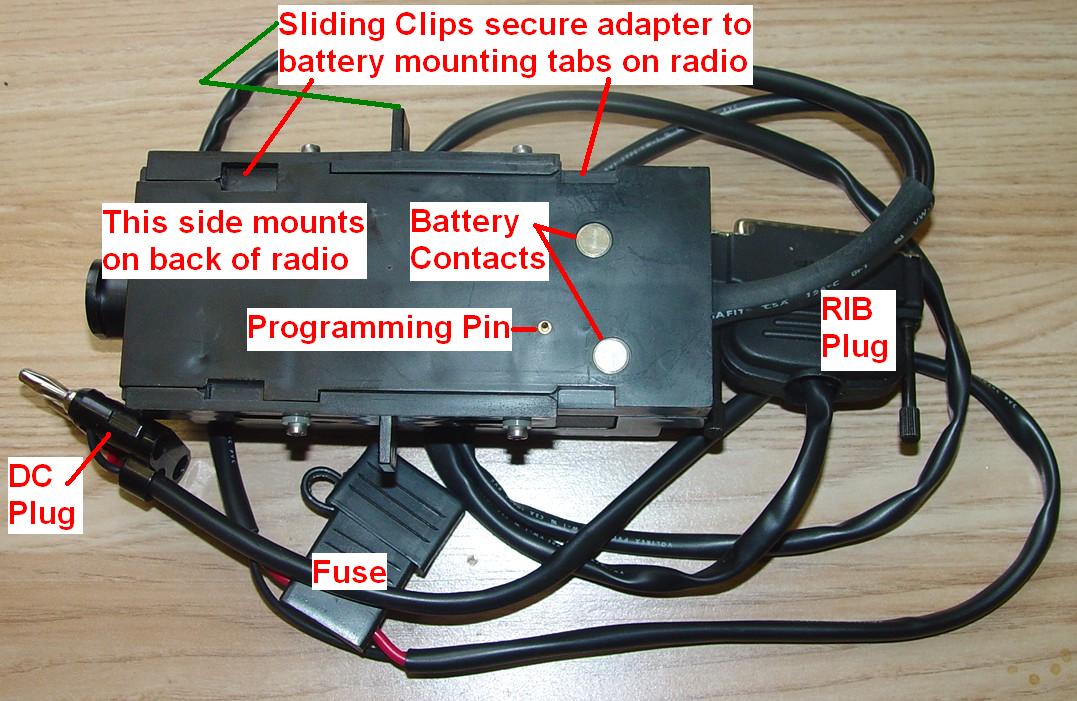
Here's a photo of the side of the programming adapter that mounts onto the back of the radio. You remove the battery and install this adapter in its place. Sliding clips on each side lock the unit to the battery mounting tabs on the radio:
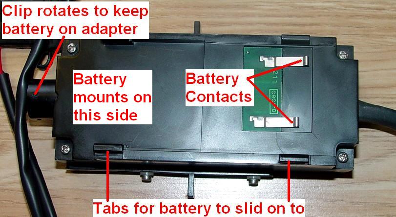
You can then slide the battery onto the back of the adapter if you don't have other power available. A rotating mechanism at the bottom of the unit keeps the battery latched in place:
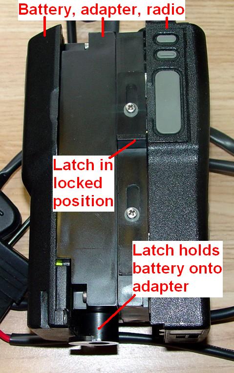
Here's what the whole thing looks like when in use:
There is nothing adjustable inside the radios. All alignment and settings are done with RSS: output power, deviation, low frequency compensation, frequency warp, and squelch. Power and deviation are aligned at eight frequencies in each of the 895.5 to 902.5 MHz, and 935.5 to 941.5 MHz bands.
One program handles the 800 MHz and 900 MHz GTX mobiles and handhelds, all variations. It does seem to be Windows-friendly, however I have not programmed a radio by running it in anything other than pure MS-DOS. The software permits programming of all conventional and some trunking features, viewing of all trunking controlled parameters, and contains some helpful service aids for troubleshooting purposes. The Motorola GTX Radio Service Software (RSS) RVN-4150, Release 04.00.01a (06-Oct-00) for Privacy Plus (PP) / LTR currently supports the following handheld radio models:
'Standard' full-featured handhelds have keypad and display.
Model Number Description Band & Power
H11UCD6CB1_N GTX/PP Handheld
800 MHz, 3 watt
H11WCD4CB1_N GTX/PP Handheld
900 MHz, 3 watt
H11UCD6CU1_N GTX/LTR Handheld
800 MHz, 3 watt
H11WCD4CU1_N GTX/LTR Handheld
900 MHz, 3 watt
'Basic' model handhelds have no keypad or display.
Model Number Description Band & Power
H11UCC6DB1_N GTX/PP Handheld
800 MHz, 3 watt
H11WCC4DB1_N GTX/PP Handheld
900 MHz, 3 watt
H11UCC6DU1_N GTX/LTR Handheld
800 MHz, 3 watt
H11WCC4DU1_N GTX/LTR Handheld
900 MHz, 3 watt
The code plug is stored in the microprocessor electronics, which resides inside the plastic housing. If you swap housings and this board, your model number, serial number, and code plug information goes with it.
Operating Deficiencies or Restrictions:
The GTX handhelds don't have any power output problems, however the deviation varies greatly with frequency, probably because the algorithm works the same as it does for output power on the mobiles.
On the handhelds with a keypad and display, channel selection is done via the up/down buttons on the keypad and the detent knob on the top selects the talk group. The knob is useless for amateur use with conventional channels. On handhelds without a keypad or display, the detent knob on top selects one of 16 channels: 12 trunking (3 talk groups in 4 systems) and 4 conventional.
Scan lists must be set up via RSS. Scanning is enabled with a button on the front panel or keypad. You can lock out channels from the front panel but if they're not selected ahead of time, you can't add them manually (like you can do with the MaxTrac). There's no "priority" channel either. Unfortunately, the one mandatory trunking channel will also be monitored when you enable scanning.
The keypad on GTX handhelds can send DTMF tones. You must enable the keypad - every time you turn the radio on - by pressing the button labeled "HM" first. You can then either press the required digits, which will cause the radio to begin transmitting automatically, or press and hold the PTT button and press the required digits. The radio will remain transmitting for a second or so after you stop dialing. Note that the radio will only generate the standard 12 digits used for making telephone calls; even though there are 16 buttons, the right-most column does not generate tones - they always perform their indicated functions. The tones are generated internally, not from the keypad, so a 16-digit modification is not possible.
The DTMF keypad must also be enabled on each mode you wish to use it on. You do this in the RSS on the mode screen. There's a field on the right side of the screen labeled "PHONE"; enable or disable this as desired for each mode. You must enable this AND activate the keypad on the radio before any DTMF tones will be sent.
On the GTX handhelds, there are two small buttons on the side above the PTT button. On radios with the keypad and display, the upper button toggles MONITOR mode, which puts the receiver into carrier squelch, and the lower button is the SELECT button which chooses menu options. On radios without the keypad and display (often called the BASIC model), the upper button toggles SCAN mode on and off and the lower button toggles MONITOR mode, which puts the receiver into carrier squelch. Pressing the MONITOR button will put the receiver into carrier squelch and a small loudspeaker icon will appear on the display when this is done. You can not force open the squelch on the receiver by twisting a knob or pressing or holding a button (like you can do with the MaxTrac). The MON button and the speaker icon only operate under specific circumstances:
On the GTX handhelds, there's an LED on the top panel. This lights up GREEN when the radio is detecting activity on the channel. It lights up RED when the radio is transmitting. On radios without the keypad and display, it also gives a double YELLOW flash about once every four seconds to let you know that scanning is active. You're almost flying blind without that front panel display.
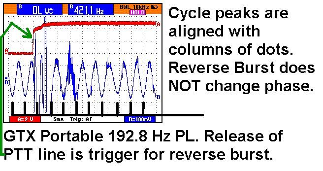
The GTX PrivacyPlus handhelds have a problem generating the PL reverse-burst tone used to squelch a receiver without any audible noise burst. It works - sometimes. The LTR models work properly all the time. I looked at the demodulated audio with a storage oscilloscope and found that there's a big spike when the PTT button is released, but the post-release tone is still completely in phase with the pre-release tone. Therefore, the receiver doesn't close its squelch because there's no reverse-burst transmitted. The DPL algorithm is different and works perfectly. The mobile radios do not have any problem with PL or DPL (this is one good reason why you may want to use DPL on your 900 MHz repeater input. DPL takes just a bit longer to initially detect than tone PL, and under some circumstances it will drop out more frequently than tone PL, but it's highly immune to intermodulation noises.) Here's a scope trace of the PTT signal on a GTX handheld (red trace, low = PTT depressed) and the flat RX audio (detected PL) from a nearby GTX mobile (blue trace). Note that the phase of the PL signal is the same before and after PTT is released. A true reverse-burst signal would have 120-240 degrees of phase shift, which would be quite noticeable on the scope.
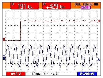
For comparison, below is a similar photo taken from a UHF MSF5000 base station. The top (red) trace is the PTT line being released. The bottom (blue) trace is the audio (100.0 Hz PL) being sent to the RF tray. Notice how the reverse-burst phase shift begins 20 mS after the release of PTT. The actual peak of the next full cycle shows 13.2 mS delay. Since each cycle of PL takes 10 mS (100.0 Hz PL is very scope-friendly), this offset is 32% of 360 degrees, or just about 120 degrees, which is what the reverse-burst is supposed to be. Too bad the designers of the GTX handheld got it wrong.
GTX Handheld Accessories:
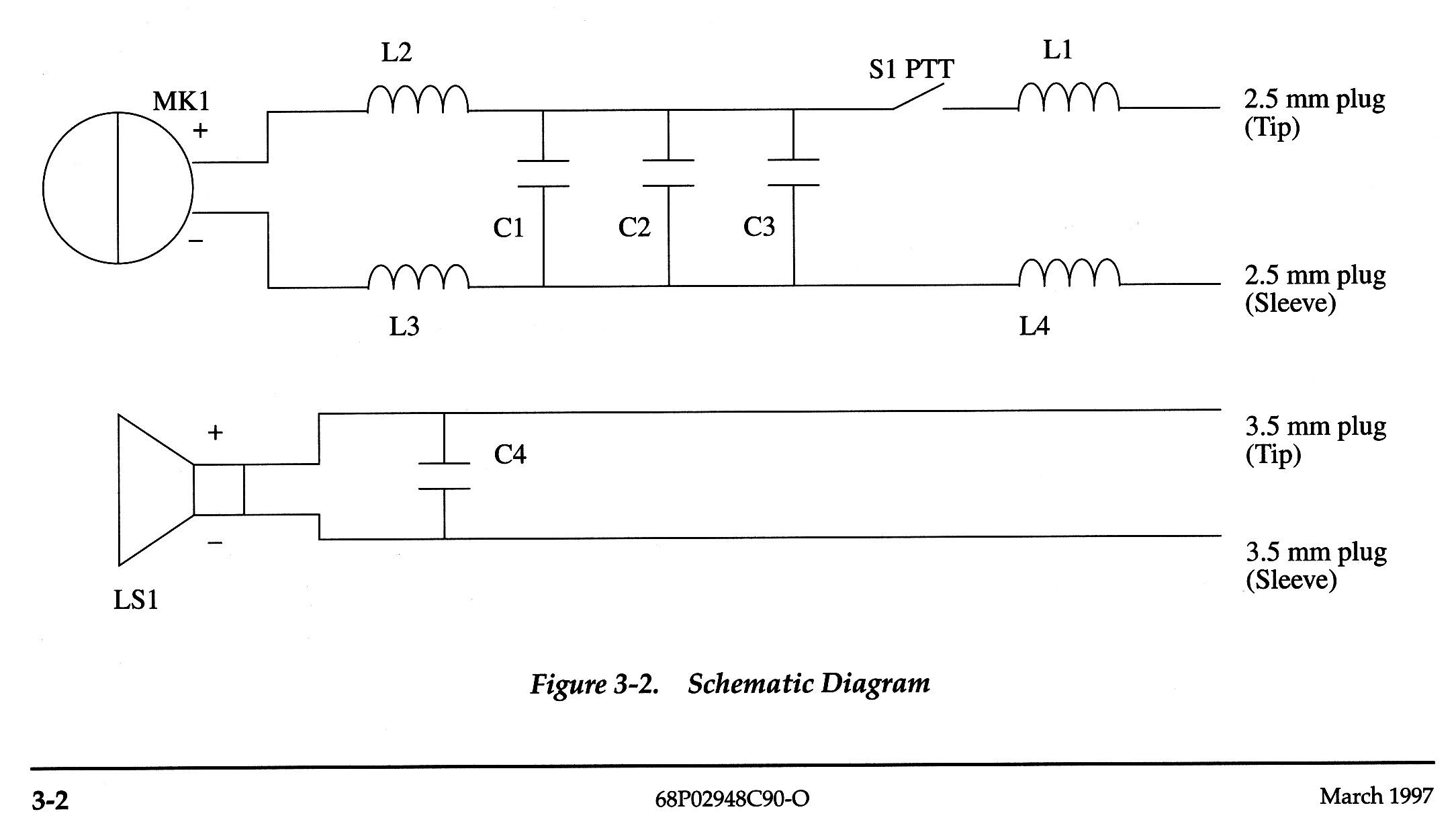
The GTX handheld can use many of the same accessories as the GP300 radios. The mike input jack is a 2.5 mm (3/32 inch) tip/sleeve connector with DC on it. External Audio should be capacitor-coupled. A 33k resistor across the microphone plug will activate the PTT line. The speaker output jack is a 3.5 mm (1/8 inch) tip/sleeve connector. You can insert two separate plugs or one molded assembly of two plugs, 7.6mm (0.300 inches) center to center. Here's a photo and schematic of an HMN9026:
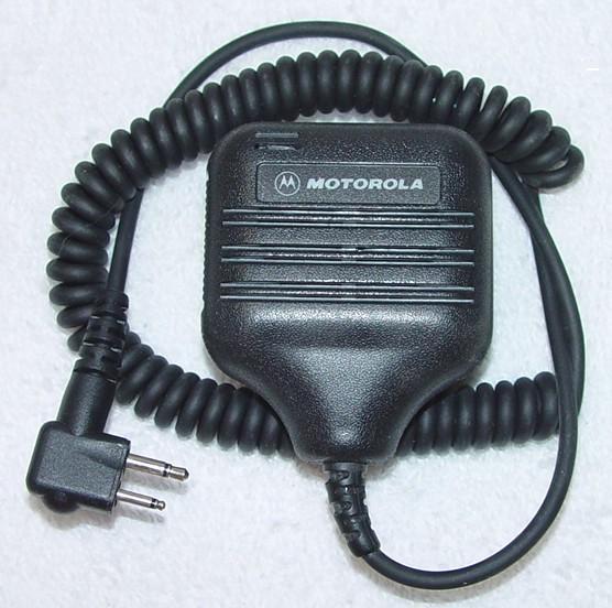
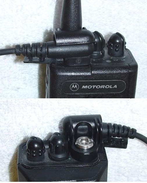
The speaker/mike tends to unplug itself during use. Here's a photo of the above unit when plugged in:

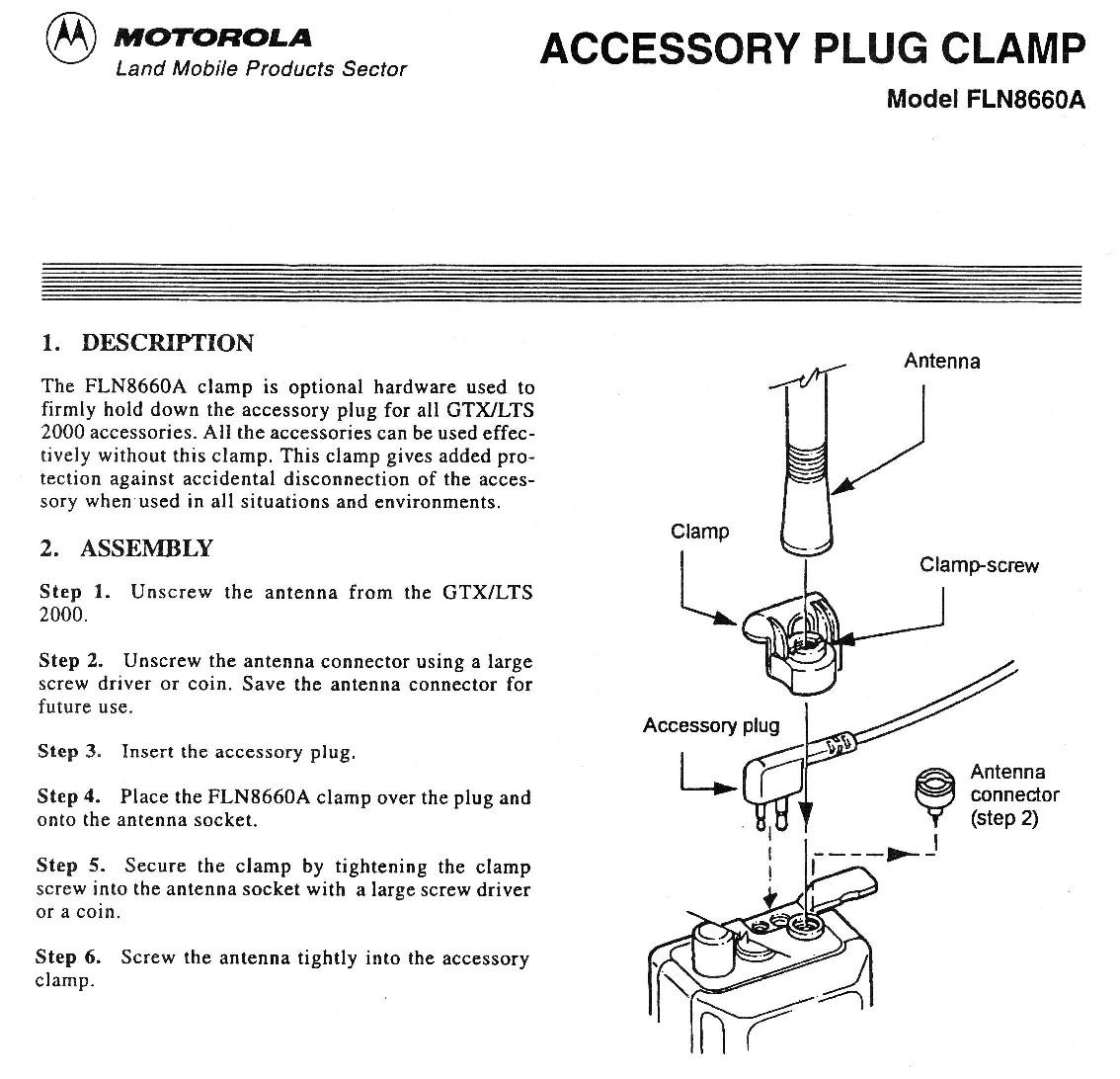
Motorola came up with an accessory clamp (FLN8660A) to hold the speaker/mike plug securely to the radio. Here's the instruction sheet that comes with it:
It replaces the antenna adapter (shown below) and securely holds the remote speaker/mike into the radio:
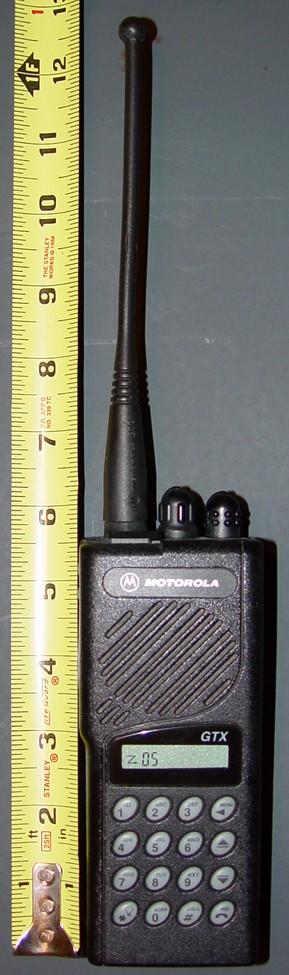
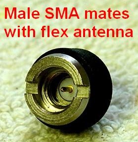
The antenna on these radios is a half-wave flexible dipole or a stubby quarter-wave vertical. The radio is 6-1/4 inches tall, and the antenna adds another seven inches. The long SMA connector has an inner contact and outer threads. An antenna adapter is required between the flexible antenna and the radio itself. The adapter part number (in case yours is missing) is now (in January 2007) 5880636V01 (it was 5880376L01); it costs about $9 and is only available from Motorola, or possibly an eBay seller. The flexible antenna with an SMA female connector screws into the top of it.
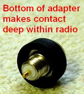
The other end screws into the radio. The radio case threads are NOT the same as SMA threads, and the contact point for RF is deep within the radio itself. The center pin makes contact with a brass strip about 3/8 of an inch from the top of the radio.
There are commercially available BNC and N adapters that will screw into the antenna adapter on top of the radio, in place of the flexible antenna.
The GTX handheld runs on 7.2 volts (nominal) DC. If you want to power it externally, you will need to regulate the voltage down to this level. It can draw about 1.3 amps when transmitting (spec sheet says 1.5 amps maximum). If you are going to use one while mobile then building up a cigarette lighter adapter might be a good idea.
There are slow and rapid-charge, single and multiple unit battery chargers available for these radios. The slow charge single unit is model HTN9702A and can be identified by a single "Charging" LED on the front, which will light up red whenever a battery is being charged. The power pack for this unit puts out 12 Volts DC at 0.2 amps and is part number 2580955Z02. Here's a photo of a slow charger:
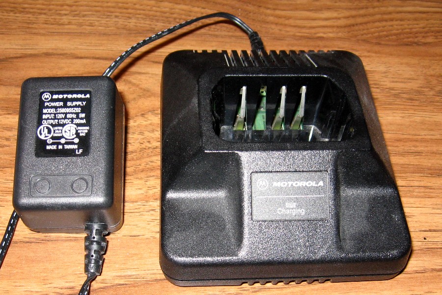
Photo by Joe N1LES.
If you lose the power pack for your slow charger or it dies, you can make something yourself. The connector is available through RadioShack: part number 274-1571. This coaxial connector is 3.5mm diameter outside, 1.3mm diameter inside; it's their type/size "H". The center terminal is positive. You will need 12 volts DC at 200mA. The Jedi series charger has the same connector and power requirements. This information was provided by Jeff W6JK.
The rapid charge single unit, model HTN9042A, can be identified by a single "Charging / Complete" LED on the front panel. The LED lights up red during the rapid charge cycle and green when the charge is complete (90 minutes), at which time the battery will be trickle-charged. Some documentation for this charger says it will charge all NiCd and NiMH packs, although I have not seen a Motorola NiMH battery for GTX radios. The power pack for the rapid charger puts out 13.8 Volts DC at 0.9 amps and is part number 2580600E01. The single unit chargers can handle a loose battery without a radio. Here's a photo of a rapid charger:
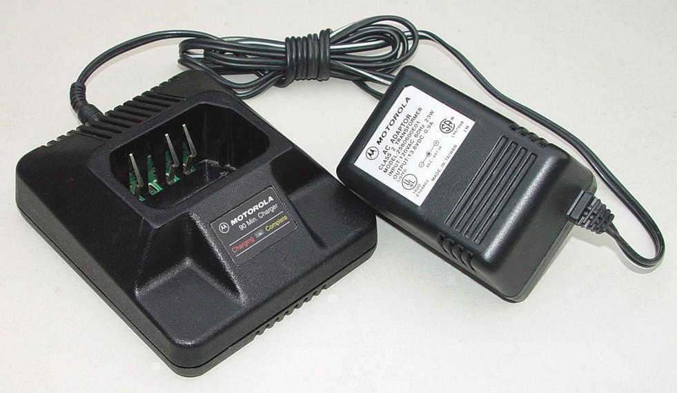
If you lose the power pack for your rapid charger or it dies, you can make something yourself. The connector is available through RadioShack: part number 273-1573. This coaxial connector is 5.5mm diameter outside, 2.5mm diameter inside; it's their type/size "N". The center terminal is positive. You will need 13.8 volts DC at 900mA. This connector also fits the Jedi rapid charger, but the Jedi needs 13.8 volts DC at 1.5 amps; that power pack is part number 2580162R01. This information was provided by Jeff W6JK.
I've only used Nickel-Cadmium (NiCd) batteries in my rapid charger. Motorola batteries come in 600 and 1200 milliamp-Hour (maH) capacities. Other vendors sell larger capacity batteries.
There's also a vehicular charger available, p/n RLN4833A that operates on 12VDC and draws up to 800mA. An electronic module plugs into a standard vehicular accessory (cigarette lighter) socket, then you slip your GTX portable into the stand, and the stand sits in a bracket that's mounted in the vehicle (not shown in the photo below). You can see this unit in the GTX Portable Parts catalog, available on this web site. According to Motorola's sales information:
"The vehicular traveling charger ensures constant communication while on the road. It allows rapid charging of the battery while using the radio. Users can talk immediately once the charger is connected and transmit from a previously "dead" battery in just five minutes. The vehicular travel charger includes a voltage-regulated adapter, custom charger base, mounting bracket and coil cord. It's ideal for public safety, utility and construction markets."
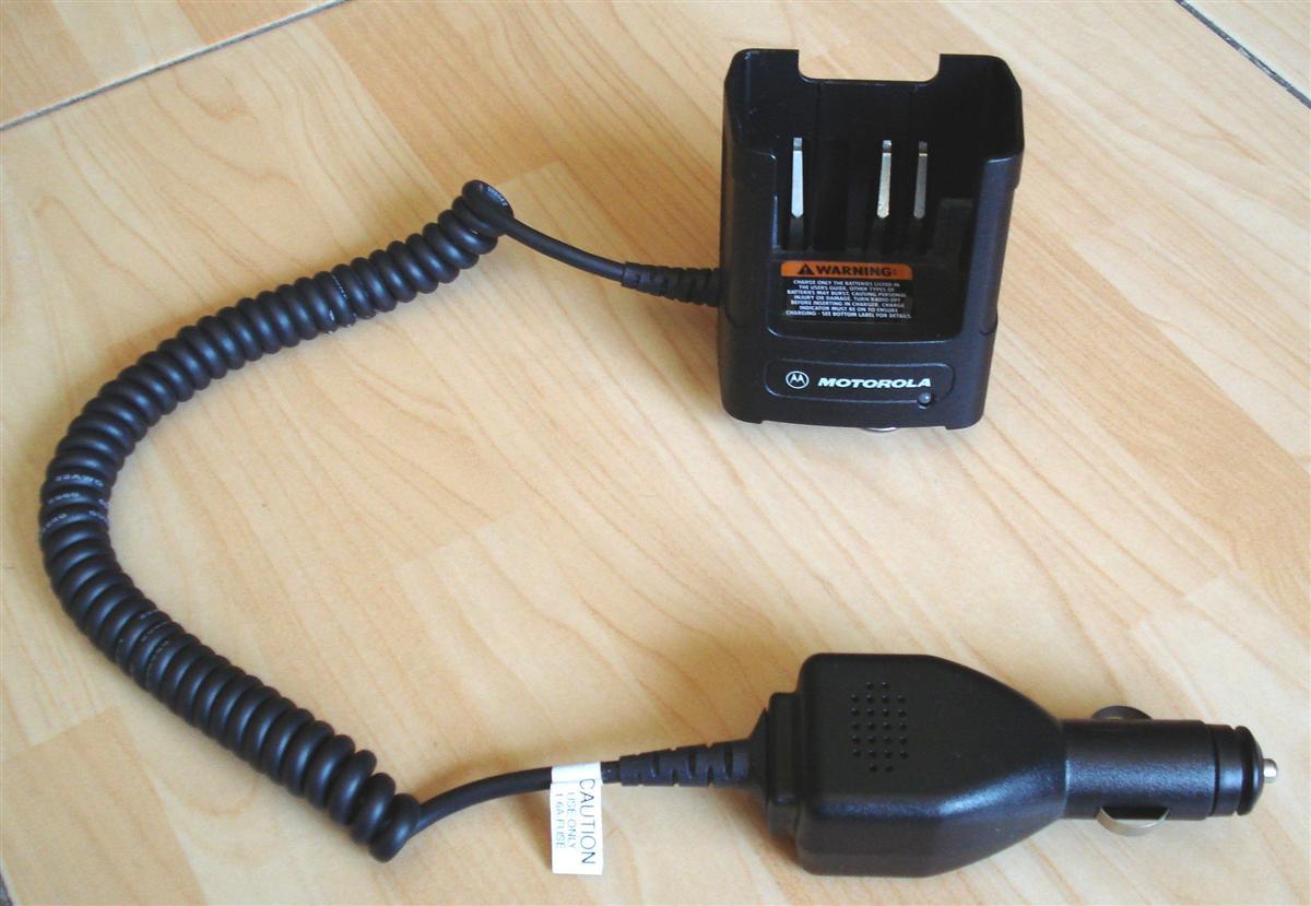
Photo by David XE2DAK.
The printing on the keypad membrane is easily worn off. You can buy just the keypad membrane for about $3 as part number 7580427K01 (for GTX/LTR; this part is NLA, and has been replaced by 7585650L01) or 7580428K02 (for LTS2000). Note that this part does NOT come with the housing kits FHN5873A (for GTX/LTR), FHN5874A (for LTS2000), FHN5874B (for LTS2000 Full SmartZone), or FHN6001A (for LTS2000 SmartZone Plus), which costs around $38 each.
A replacement 900 MHz flexible antenna is p/n 8505241U04. It's the same for all models of the 900 MHz GTX handheld and will set you back about $30 new from Motorola. They're no longer available from Motorola but you can find them on ebay (US sellers) for about $10 (in May 2018). The HT1000, Saber, and Visar radios apparently use the same antenna.
There's also a stubby flexible antenna, p/n 8505241U06, that's considerably shorter. The photo below shows it next to a U.S. quarter.
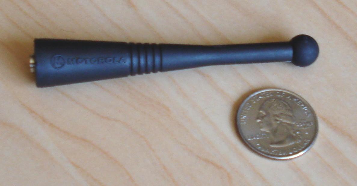
Photo by David XE2DAK.
Acknowledgements and Credits:
Some of the information about hex-editing this file was obtained from Bruce KC7GR and other sources on the web.
MaxTrac, GTX, PL, DPL, Radius, GM300, RSS, "Radio Service Software" and Hear-Clear (and a bunch of other things) are registered trademarks of Motorola, Inc.
Jeff W6JK gave me useful information about the "basic" model handheld radio and supplied the photo of that unit. He also provided the information about the power requirements and coaxial power connectors used by the handheld chargers.
Joe N1LES supplied the photo of the slow charger for the handheld radio.
David XE2DAK supplied the photos of the stubby antenna, vehicular charger, and the radio with the stubby antenna.
Schematics, specifications, and other scanned data sheets came from Motorola manuals and documents. Copyright on these items is retained by Motorola.
Contact Information:
The author can be contacted at: his-callsign [ at ] comcast [ dot ] net.
Back to the top of the page
Up one level (GTX index)
Up two levels (Moto index)
Back to Home
This page originally posted 03-Dec-07.
Unless otherwise noted, article text, photographs, and hand-coded HTML
© Copyright 2007 By Robert W. Meister WA1MIK.
This web page, this web site, the information presented in and on its pages and in these modifications and conversions is © Copyrighted 1995 and (date of last update) by Kevin Custer W3KKC and multiple originating authors. All Rights Reserved, including that of paper and web publication elsewhere.