Up two levels (Moto index)
Back to Home
Radio Information,
Notes, and Tips
-Mobile Section-
By Robert W. Meister WA1MIK

|
Up one level (GTX index) Up two levels (Moto index) Back to Home |
GTX 900 MHz Radio Information, Notes, and Tips -Mobile Section- By Robert W. Meister WA1MIK |
|
Model Specifications:
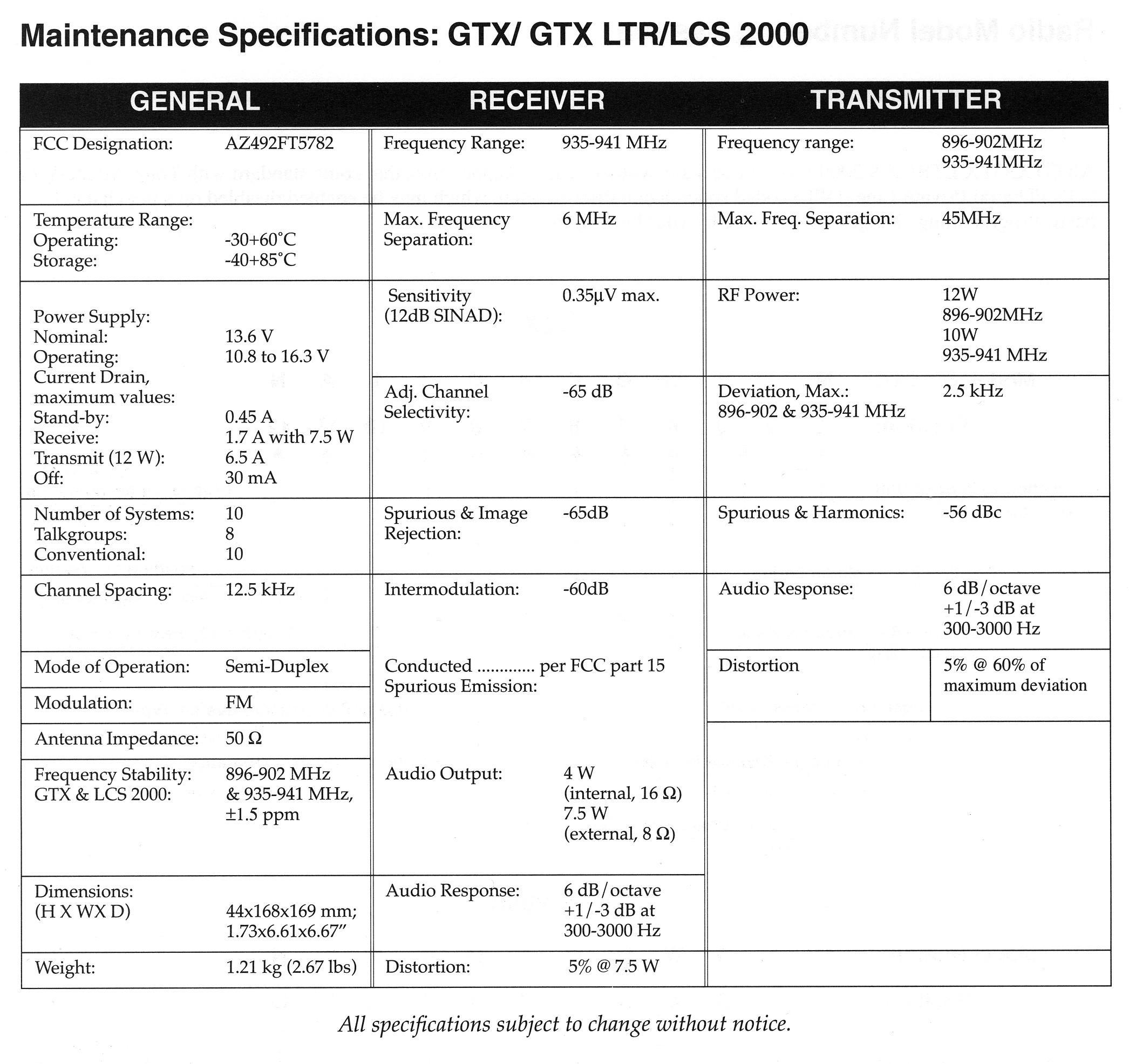
These are the specs from the GTX service manual that included the LCS2000 models:
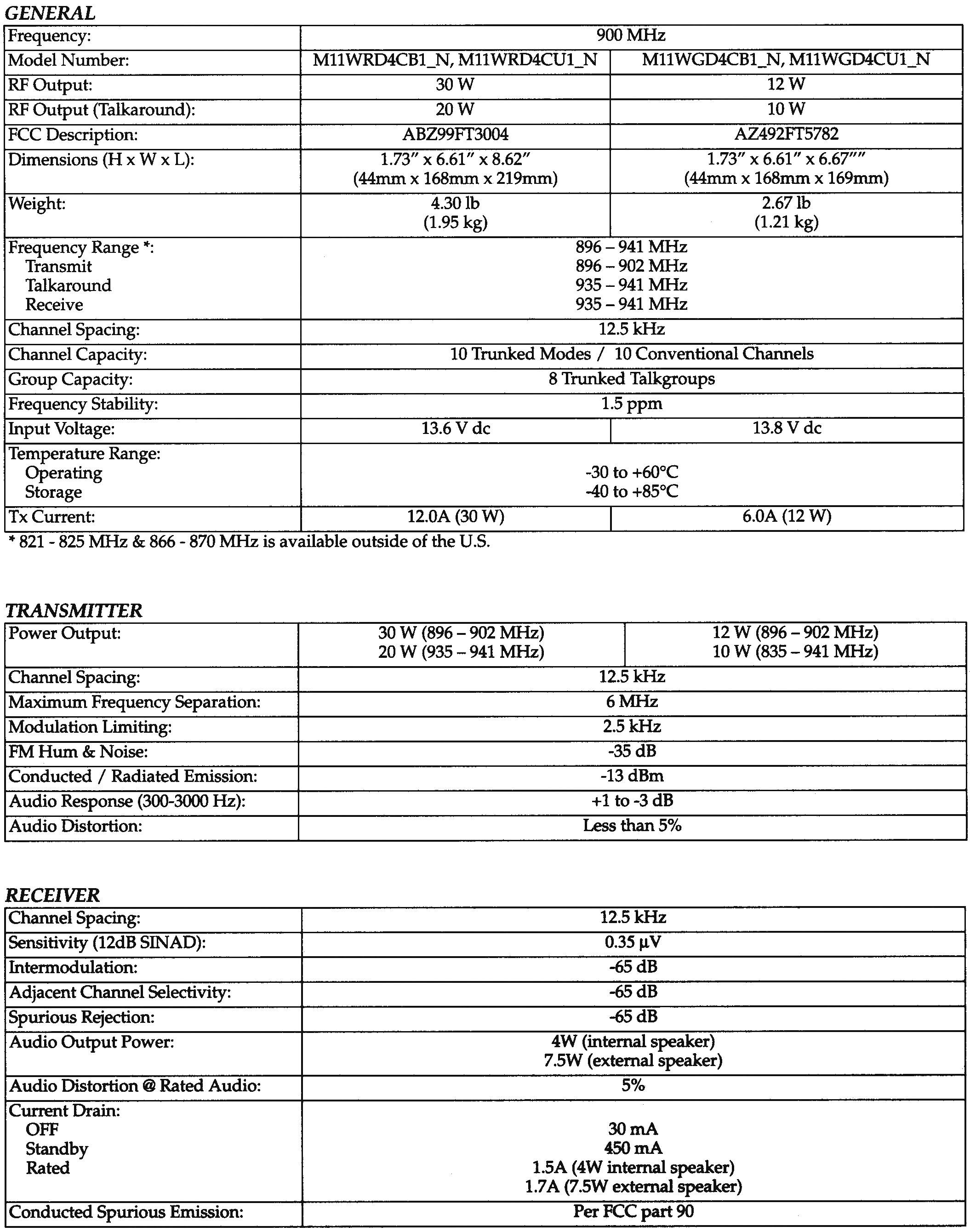
These are the specs from the newer GTX LTR/PP-only service manual:
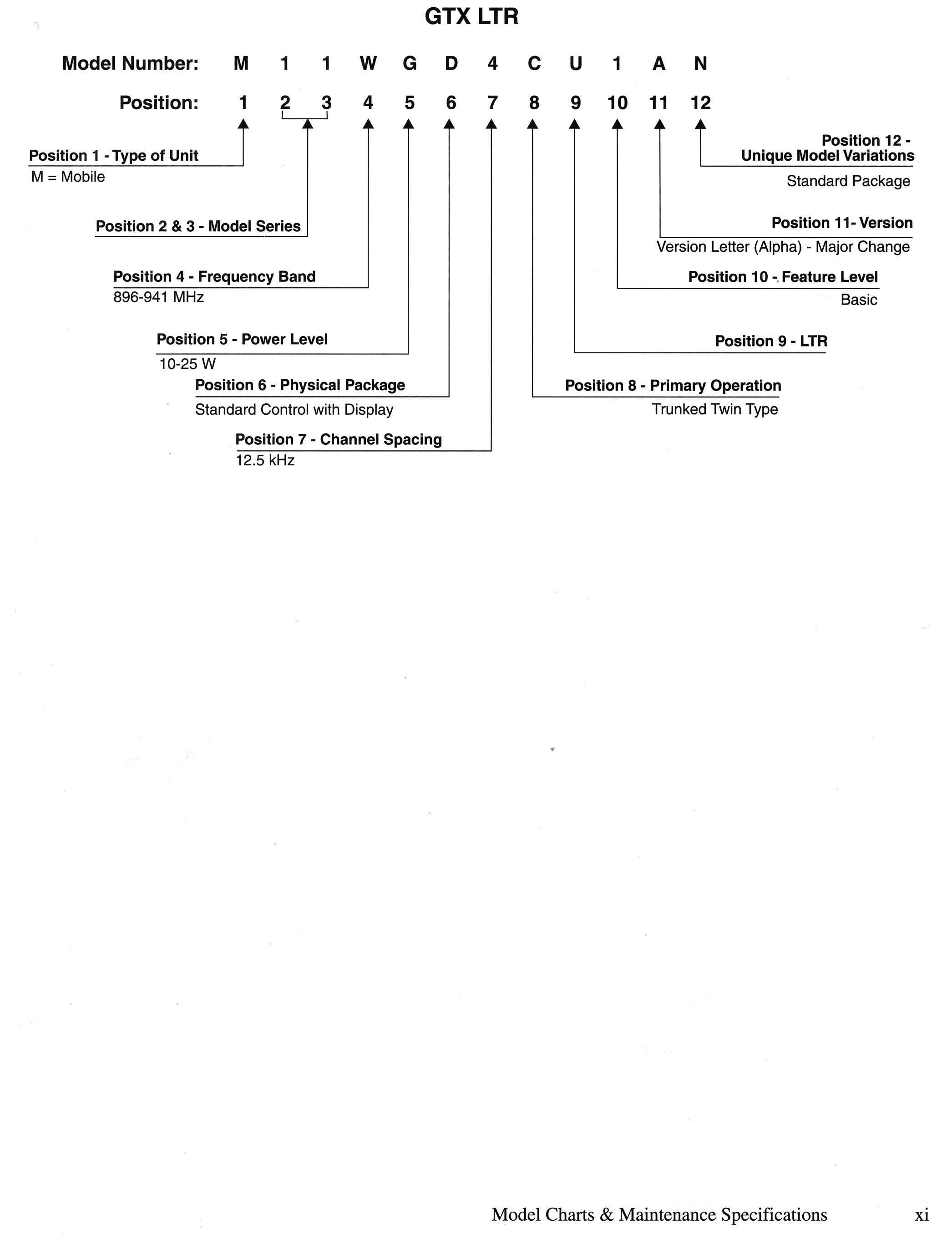
Model Number Charts:
A typical GTX 12-watt mobile model number is M11WGD4CB1AN. The 4th character of the model number must be "W" for use in the 900 MHz band. The "M11Uxx..." models cover radios that operate in the 800 MHz band. Conversion is very difficult if not impossible due to the extensive use of surface-mount components on both sides of the circuit board and the lack of field-installable or upgradeable firmware. 800 MHz MaxTracs can be successfully converted to 900 MHz service, but not 800 MHz GTXs. There are also high-power 30-watt versions; these have the letter "R" in the 5th position of the model number instead of "G".
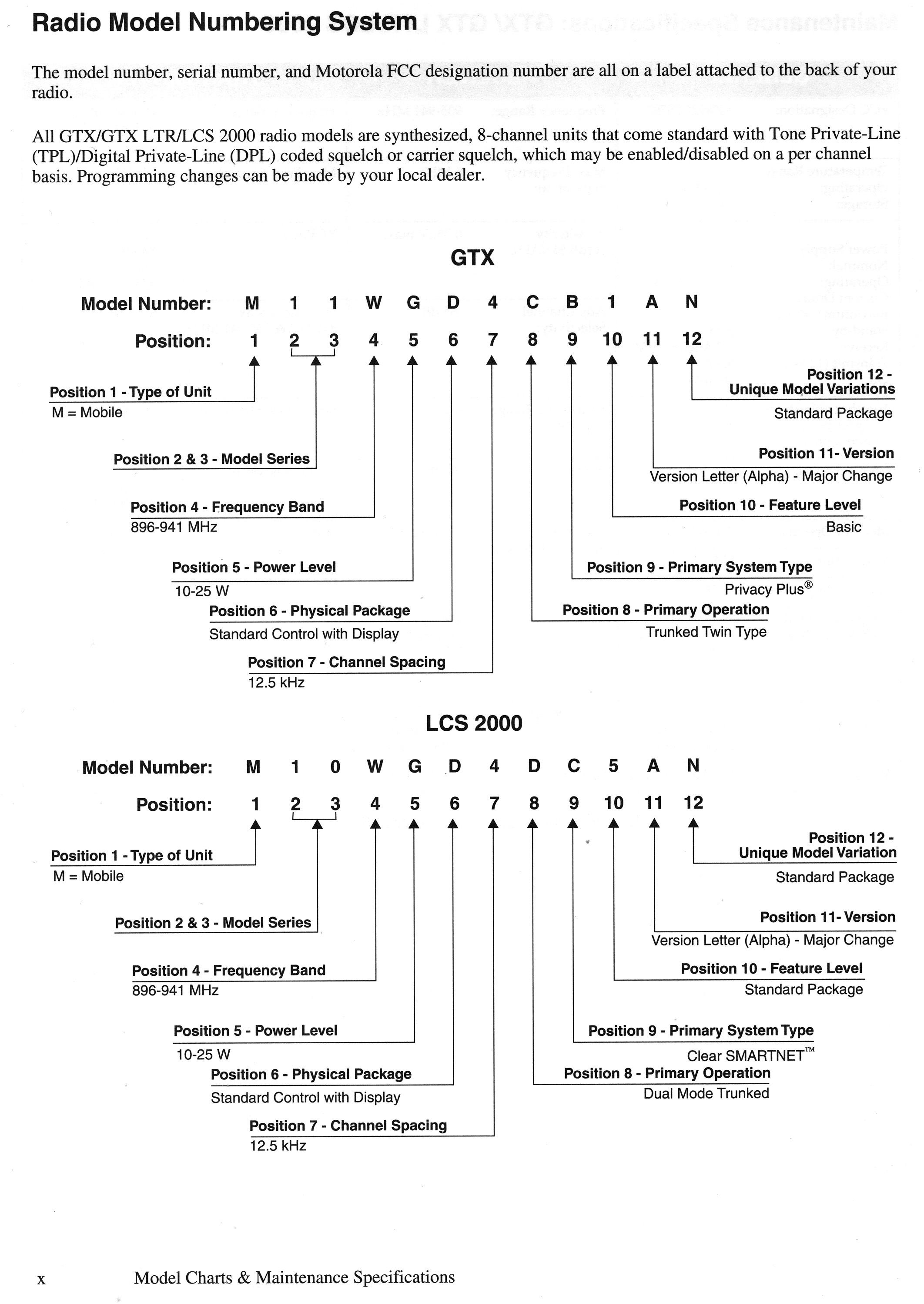
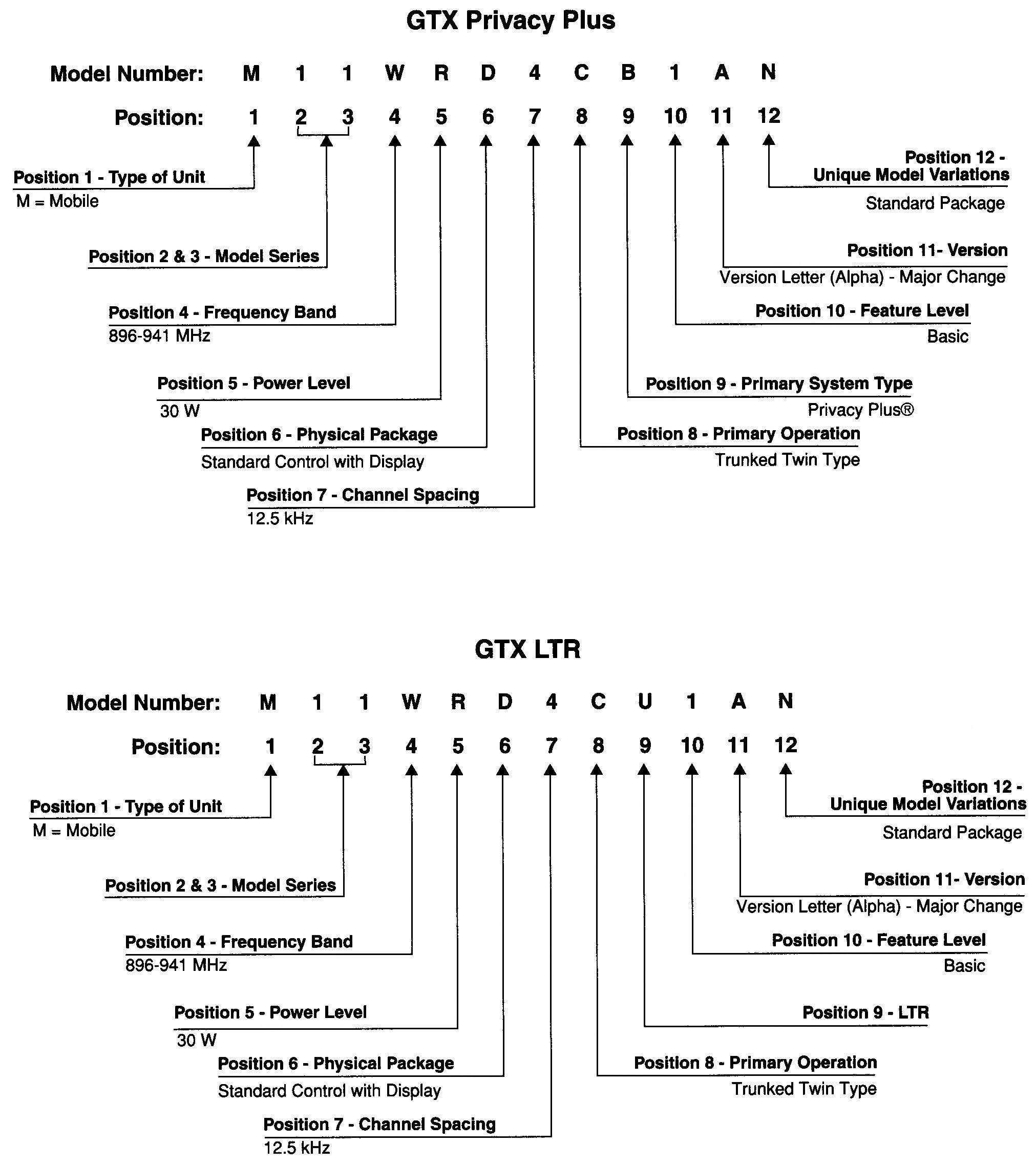
These are the model number sheets from the newer GTX LTR/PP-only service manual:

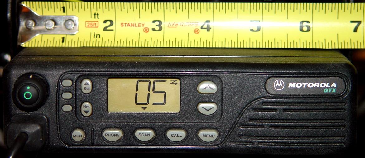
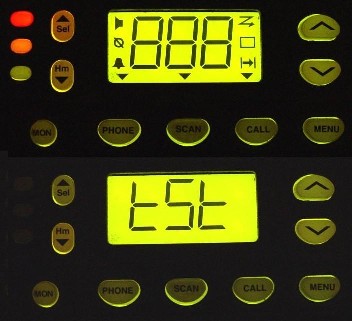
Display:
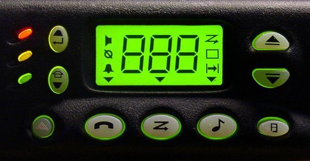
The GTX mobile radio has an LCD display capable of showing three seven-segment characters plus nine icons around the outside. All segments and icons will be shown when the radio is first turned on, then the display shows "tSt", then it displays the last used channel number. These first two screens are shown in the photo below:
The various icons, starting at the upper left corner and working counter-clockwise,
are:
To the left of the display there are three other colored indicators, which
are all lit upon power-up. From top to bottom, they are:
Programming:
The GTX mobile uses the same RIB cable as for a MaxTrac, Radius, GM300, SM50, etc., and it still plugs into the front panel RJ-45 MIC jack.
There is nothing adjustable inside the radios. All alignment and settings are done with RSS: output power, deviation, low frequency compensation, frequency warp, and squelch. Power and deviation are aligned at eight frequencies in each of the 895.5 to 902.5 MHz, and 935.5 to 941.5 MHz bands.
One program handles the 800 MHz and 900 MHz GTX mobiles and handhelds, all variations. It does seem to be Windows-friendly, however I have not programmed a radio by running it in anything other than pure MS-DOS. The software permits programming of all conventional and some trunking features, viewing of all trunking controlled parameters, and contains some helpful service aids for troubleshooting purposes. The Motorola GTX Radio Service Software (RSS) RVN-4150, Release 04.00.01a (06-Oct-00) for Privacy Plus (PP) / LTR currently supports the following mobile radio models:
'Standard' full-featured 'Low-Power' mobiles.
Model Number Description Band & Power
M11UGD6CB1_N GTX/PP Mobile
800 MHz, 15 watt
M11WGD4CB1_N GTX/PP Mobile
900 MHz, 12 watt
M11UGD6CU1_N GTX/LTR Mobile
800 MHz, 15 watt
M11WGD4CU1_N GTX/LTR Mobile
900 MHz, 12 watt
'Standard' full-featured 'High-Power' mobiles.
Model Number Description Band & Power
M11URD6CB1_N GTX/PP Mobile
800 MHz, 35 watt
M11WRD4CB1_N GTX/PP Mobile
900 MHz, 30 watt
M11URD6CU1_N GTX/LTR Mobile
800 MHz, 35 watt
M11WRD4CU1_N GTX/LTR Mobile
900 MHz, 30 watt
Operating Deficiencies or Restrictions:
The GTX mobile has a MON button on the front panel. Pressing it will put the receiver into carrier squelch and a small loudspeaker icon will appear on the display when this is done. You can not force open the squelch on the receiver by twisting a knob or pressing or holding a button (like you can do with the MaxTrac). The MON button and the speaker icon only operate under specific circumstances:
Squelch level is adjusted with a soft-pot on one of the RSS screens. There is no physical (i.e. user-adjustable) squelch pot, and while it would be nice to have one, adding one is not practical as the discriminator audio output and the RSSI signal are fed to a custom audio IC which is tied to the microprocessor. Firmware in the radio decides when to squelch or un-squelch the audio. All the decision work is done in the special IC and the microprocessor. I'm sure someone could kludge something into the circuit to fake it out, but the surface mounted components are quite tiny and are on both sides of the board. The interior of a GTX mobile looks like they took a handheld and unfolded it onto one circuit board.
The GTX mobiles do not properly regulate or control their output power when the radio is transmitting outside the 896-902 or 935-941 MHz ranges. For example, if the radio is aligned with RSS to put out 12 watts, it will continue to do so on 902.4125 MHz and 902.4875 MHz. However, it might output 0.8 watts on 927.5000 MHz and 19 watts on 927.4875 MHz. It might also output 10 watts on 927.6000 MHz. Whatever it decides to make is what you'll get. The problem seems to always occur, regardless of code plug hacks, if scanning is enabled. Deviation doesn't seem to suffer this kind of irregularity but the deviation will usually be lower on the talk-around frequencies. A companion article exists for adding manual power control to a GTX mobile.
Speaking of power, the 900 MHz GTX mobile uses an RF power amplifier module, MHW2821-2, to develop up to 19 watts of output power. I have found these for sale on a popular auction site for about $20 each. The -1 part is for the 800 MHz radio and won't work properly in the 900 MHz radio. One radio I had would only make 6 watts, and even at that level it would drop off after 15 seconds of transmission. Replacement didn't take long, but getting the old module out is difficult. It's well-soldered to the back of the main circuit board and it takes a heat gun to remove it; all of this heat also tends to destroy the bad module, and if you're not careful, the solder on nearby components will also melt and parts WILL go flying off the board.
There are two sets of up/down buttons on the mobile front panel: the larger ones on the right of the display choose the talk group; the smaller ones (unfortunately) on the left side of the display choose the channel.
Scan lists must be set up via RSS. Scanning is enabled with a button on the front panel. You can lock out channels from the front panel but if they're not selected ahead of time, you can't add them manually (like you can do with the MaxTrac). There's no "priority" channel either. Unfortunately, the one mandatory trunking channel will also be monitored when you enable scanning.
The transmitter output power settings can be adjusted through the board replacement procedure, such that you can get an error if you later try to adjust the output power through the alignment menu. RSS shows an error message on the screen, similar to this:
WRONG COMPENSATION ADDER VALUES
MUST READJUST COMPENSATION ADDERS
Your only choice is to press F2 to continue, which puts you right back into the service menu. The compensation adders seem to be related to the 16 individual settings for the output power in the board replacement procedure.
You can blank and reinitialize the board, which will fix it, but that's rather drastic. Another solution that seems to have worked for several people is to go back into the board replacement menu and run through all of the adjustment sections in order, pressing F8 to accept what's already there, except for the output power calibration screen: adjust each value to about mid-scale on each of the 16 alignment points. After saving the alignment data, go back to the output power setting on the service menu and it should operate normally, without any error messages. You can go back and readjust the individual alignment points if necessary; just don't push them to vastly different values. Typical numbers are about 2/3rds of full scale.
I discovered another strange condition. One of my radios has seven modes programmed, two of which have HearClear enabled (01 and 05). These two modes are also the only entries in the radio's scan list. I added one more mode (07) that duplicates one of the scanned ones, but with HearClear DISabled. If the radio is scanning and hears activity on mode 01, I manually change to the non-HearClear mode (07), while leaving everything else the way it is. For some reason, the radio still has HearClear enabled, even though the mode I've manually selected does not. Additionally, if I manually select the non-HearClear mode (07), turn on scanning, and the radio hears a signal on the non-HearClear mode (07), it will stop scanning on that mode but will still have HearClear enabled. If I turn off scanning, HearClear gets turned off and the mode operates as it's been programmed. What's more interesting is that if I'm transmitting, I can still turn scanning off via the front panel button and even change modes. Either operation properly sets the HearClear setting on the non-HearClear mode. I haven't tried scanning two modes where HearClear is enabled on one but disabled on the other.
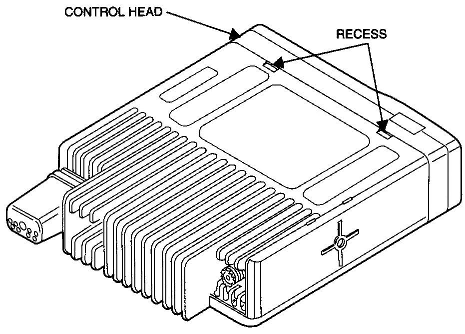
Visible Model Differences:
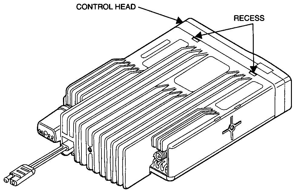
The low-power radio has a two-pin DC power connector mounted to the main circuit board. It sticks out through the heat sink on the rear of the radio. Here's an image of the bottom and rear of the low-power radio:
The high-power radio has a two-pin DC power connector mounted on a short DC cable that fits through a molded grommet in the heat sink. The wires are soldered to the main circuit board. The heat sink itself also has more fin area to assist in cooling the radio. Here's an image of the bottom and rear of the high-power radio:
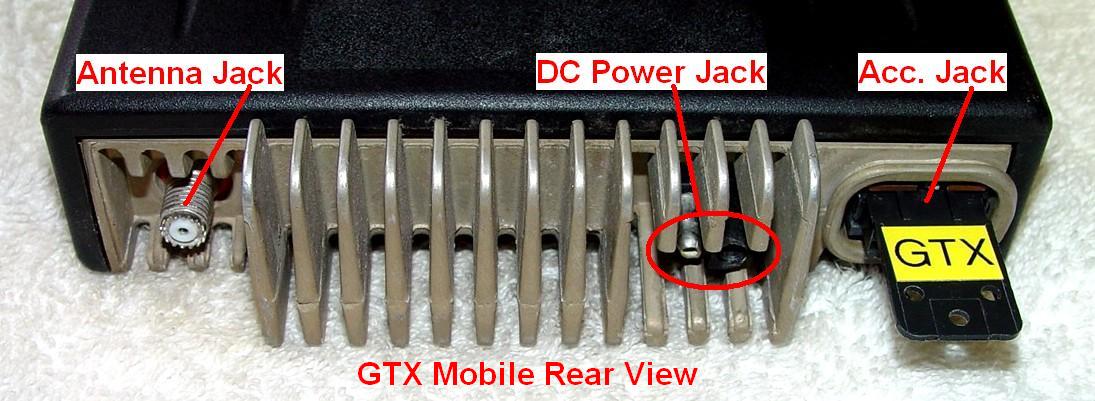
Mobile Accessory Jack Configuration:
The physical accessory jack on the back of the GTX mobile has 16 pins and is the same one used on MaxTracs, Radiuses, and GM300s, and probably other Motorola radios. The functions are similar to those used on the above radios. The pin assignments, however, are quite different. You must not put an accessory plug configured for a MaxTrac into a GTX radio without changing the jumpers. Here's a view of the back of the radio with an accessory plug inserted (click on the image for a larger view). Note that the plug in the photo has been prominently labeled for use in a GTX radio:
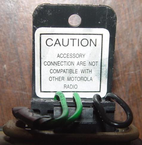
I found this label on a GTX radio's accessory plug. All grammar aside, it conveys the message rather plainly:
This view is looking at the radio accessory connector on the back of the radio, with the bottom of the radio (finned heat sink) down. Pin 1 is in the lower left corner, pin 2 is in the upper left corner, pin 15 is in the lower right corner, and pin 16 is in the upper right corner.
| GTX Mobile Accessory Jack Pin Orientation Looking From The Rear |
|||||||
|---|---|---|---|---|---|---|---|
| Top of radio housing | |||||||
| 2 | 4 | 6 | 8 | 10 | 12 | 14 | 16 |
| 1 | 3 | 5 | 7 | 9 | 11 | 13 | 15 |
The table below summarizes the location and usage of each pin. See the Internal Configuration Switch section for more information on the rows with red text, as these signals may have alternate functions in some radios.
| GTX Mobile Accessory Jack Pins and Signals | ||
|---|---|---|
| Pin # | Signal Name | Description and Usage |
| 1 | EXT SPKR - | Connect to an external speaker with pin 16 |
| 2 | EXT MIC AUDIO | Microphone-level audio input |
| 3 | EXT PTT | Push-to-talk input |
| 4 | EXT ALARM | Active low output to drive a relay |
| 5 | FLAT TX AUDIO | Line-level audio input |
| 6 | SCI DATA IN | Not used |
| 7 | GROUND | Ground for PTT and audio - NOT FOR SPEAKER |
| 8 | SCI DATA OUT | Not used |
| 9 | EMG SWITCH | Low input activates alarm functions in radio |
| 10 | IGNITION CTRL | Must be pulled high to let radio turn on |
| 11 | FLAT RX AUDIO | Flat receive audio output |
| 12 | GP I/O | Not used |
| 13 | INT SPKR | Connect to pin 16 to activate internal speaker |
| 14 | HOOK | Low input to activate RX PL/DPL |
| 15 | RSSI BUF | Analog output of rcvd signal strength: 1.5 - 4.5 VDC |
| 16 | EXT SPKR + | Connect to an external speaker or pin 13 |
NOTE: Clarification on the use of speaker pins 1, 13, and 16:
Simultaneous use of both an internal and external speaker is not recommended.
Here's part of the schematic showing the accessory jack circuitry. Note that the rear audio inputs are only activated when the rear PTT line is grounded. The microphone on the front panel is only live when its PTT button is pressed.

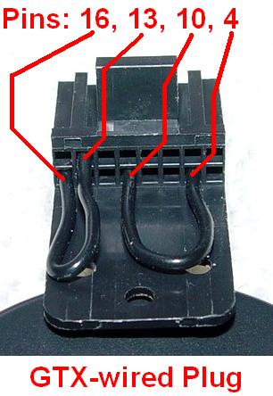
In addition to the jumper from pin 13 to pin 16 mentioned above (which enables the internal / front panel loudspeaker), you will also need to supply +13 volts to the Ignition Control input, pin 10, to get the radio to turn on. This may be left on all the time or connected to a vehicle's ignition circuit through a 1A fuse to turn the radio on and off with the ignition. If you do not use or want ignition control, you can jumper pin 10 to pin 4, the External Alarm output (an active low signal), which has a pull-up resistor on the main board and which will satisfy the Ignition Control input logic. Here's a detailed photo of these two jumpers underneath the accessory plug:
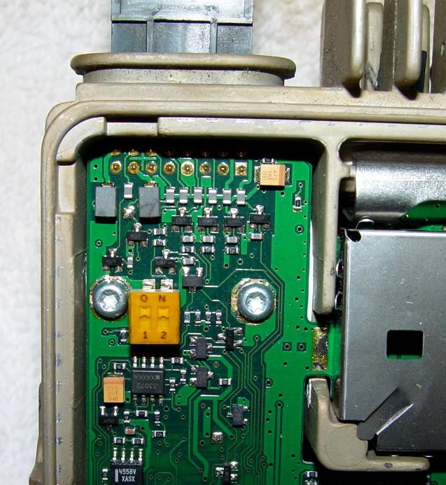
Internal Configuration Switch and Other Differences:
The newer radios have a two-section DIP-switch mounted inside on the main circuit board, behind the accessory jack. Section 2 (pins 2-4) connects a resistor to the Ignition Sense line (accessory jack pin 10), which pulls that line to a source of continuous battery voltage, eliminating the need for an external jumper on the accessory plug. Section 1 (pins 1-3) alters the function of several accessory jack signals for use with certain accessories. These changes are detailed in the table below. When looking down at the radio, section 1 (pins 1 and 3) is closest to the outside (left) edge of the radio, and the ON position is towards the rear. Here's a photo of that switch, with both sections ON, on a 12w radio owned by Ken N1KN:
| GTX Mobile Accessory Jack / DIP-Switch Configuration | |||
|---|---|---|---|
| Pin # | In/Out | Section 1 OFF | Section 1 ON |
| 3 | Input | Data PTT (Low) | PTT (Low) |
| 4 | Output | Transmitting (Low) | External Alarm (Low) |
| 11 | Output | Flat RX Audio | Muted/De-Emph RX Audio |
| 12 | Input | Speaker Mute (Low) | Public Address (Low) |
For operation with a Remote Desk Set, Public Address, or External Alarm, section 1 should be ON. For operation with a Data Modem, section 1 should be OFF.
Pin 15 now indicates System Busy (directly from the Audio_PA_Enable) and is low when the radio is passing receive audio. This is as close to a COR as the radio is ever going to be able to provide. To have the DC RSSI signal on this pin, a couple of internal components must be removed and inserted. The service manual has the details. It seems that RSSI is now a Special Application signal.
Other Common Gotchas:
In the partial schematic above, notice the components attached to the EXT_PTT signal on pin 3. There's a 5.1V Zener diode, VR0425, that's directly across this line, and a 4.7k pull-up resistor, R0423. The EXT_PTT line is active when pulled to ground by an external source. If you pull it up to +12V, you WILL instantly destroy VR0425 with over-current. It will short out, grounding the EXT_PTT line. The shorted Zener will put the radio into constant transmit mode as soon as you turn it on. The Motorola designer forgot to put a current limiting series resistor between the input signal connector pin and the rest of the radio - that one addition would have prevented this problem. If you remove the main board and look underneath near the accessory jack, you will see a small, yet obviously damaged, component - this will be VR0425. You can remove it by touching the contacts with a soldering iron; once out the radio will return to normal operation. I've seen or heard about this problem on at least four radios so far, and each has been returned to active duty once VR0425 was removed. Note that removing it and not replacing it removes the protection the diode is there to provide, so you need to take better care of the radio next time you hook it up. On the MaxTrac accessory jack all input signals run through transistor inverters with built-in input resistors. On the GTX some input signals go directly into the ASIC or microprocessor with only a shunt Zener for protection. If you plan on using the accessory jack for repeater controller interfacing (or anything else) you might want to add the series resistor(s) to your radio before something happens. It's as easy as cutting a trace and bridging it with a 1K (or so) resistor. Yes, removing the Zener restores operation of the radio, but also leaves the EXT_PTT line completely unprotected for over-voltage, static, or anything else. What would you do if you popped the ASIC or microprocessor chip (they aren't socketed)? Personally I'd figure out some way to place a resistor in series with any logic input pin plus tack a replacement Zener diode in place. Some protection is better than none.
Pin 12 (GP I/O) goes to the Audio Special Function Integrated Circuit (ASFIC) in the radio, which is managed by the internal microprocessor. The RSS makes no mention of accessing this signal. The service manual just says it's one of six signals that come out of the AFSIC which are used to enable/disable internal circuitry. There's no way to program this pin to do something useful, such as PL/DPL or Carrier Detect.
While the descriptions in the table above mention several useful signals, not all of them operate the way you'd expect. For example, the FLAT TX AUDIO input doesn't seem to work at all on my radios; maybe it's reserved for special (SP) applications.
GTX Mobile Accessories:
The GTX mobile radio uses the same two-pin DC power connector as MaxTracs, GM300s, and Radiuses. It draws about five amps when transmitting at 15 watts. This connector is on the end of a short cable on 30-watt radios. The antenna connector is the same mini-UHF female jack used by other recent Motorola products.
The GTX mobile radio can use the same microphones as MaxTracs, GM300s, and Radiuses. Probably any Motorola base or hand-held microphone with an 8-pin RJ-45 plug will work. The MIC connector pin-out is the same as on the above radios. (Microphones wired for a Desktrac base will not work.) Of the eight pins, six (pins 2 through 8) are the same as on MaxTracs with the following exception: the headset audio output (pin 8) is NOT at a constant level; it varies as the front panel volume control is rotated. Pin 1 (spare on a MaxTrac) is pulled to filtered A+ (+13V) through a 1k resistor. Pin 2 (spare on a MaxTrac) goes nowhere. There are no spare wires in the cable between the control head and the radio. These microphones are specifically listed for use with the GTX mobile radios:
External loudspeakers must be connected between accessory jack pins 1 and 16. Do not ground either of these pins as the audio amplifier IC drives both pins, and it will be damaged if you ground them. (This is not the same as a MaxTrac where one side is grounded.) Anything with 3.2 ohm impedance or greater will work.
The mounting bracket for the 12/15 watt GTX mobiles is only available as part of the GLN7317 Trunnion Kit, which includes two thumbscrews to hold the radio and several sheet-metal screws for attaching the bracket to a vehicle. The kit costs around $22. The GTX is 6-5/8 inches wide (1-3/4 inches tall and 7 inches deep including the knobs) but the MaxTrac is 7 inches wide, so the MaxTrac brackets won't really fit the GTX radio. (I suppose you could use it with some washers as spacers.)
The mounting bracket for the 30/35 watt GTX mobiles is only available as part of the HLN9640 Trunnion Kit, which includes two thumbscrews and appropriate hardware. This bracket also supports the rear of the radio at the heat sink. The retail price is about $20 in late 2007.
Differences between the GTX and the LCS2000:
This entire section, including photos, was submitted by Mark N9WYS.
The LCS2000 front panel looks a lot like the GTX, but the two radios are distinctly different.
These differences are that the GTX buttons across the bottom of its panel are labeled in text. The LCS2000 uses graphic depictions and the order is slightly different. Going from left to right on the GTX, the functions are labeled: MON, PHONE, SCAN, CALL, and MENU.
The LCS2000 function buttons are labeled: Red Diamond ("EMERGENCY"), Phone handset ("PHONE"), the "Z" Motorola uses to depict "SCAN", a musical note ("CALL") and what looks like a double-hung window ("MENU").
Depending upon what functions you have enabled in the radio, the MENU button does several things. It toggles PL on and off. It also will DELete a channel from a Scan List (known by Motorola as "Nuisance Delete"). It also displays the function "SPG" for viewing the Scan ProGram. These are some of the screens you may see when pressing the MENU button:
PL OFF:
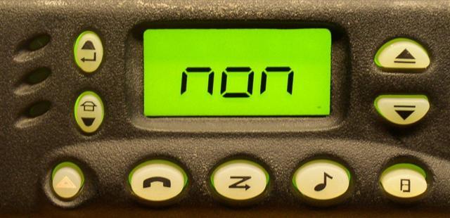
Or
PL ON:
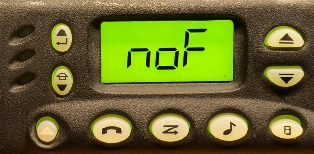
Once you get to this point, you will need to press the "Channel-Up" button to the left of the display, the one with the arrow that points down and left (like the ENTER key on your computer) to accept the change and return the display to "normal" to see your channel number. If you have the User's Guide for the GTX mobile radio, the menus and displays are identical.
Programming the LCS2000 is about as straight-forward as the GTX, but of course, it uses a different RSS (RVN4156B), which will need to be hacked for out-of-band frequency entry.
In order to make this radio fully operational, you will need to jumper the same connections on the accessory jack as the GTX: Pins 4 and 10 for Ignition Sense, and Pins 13 and 16 for Internal Speaker. You can also jumper Pins 7 and 14 to enable PL operation without a microphone hang-up box (HUB) or clip, depending on the microphone you decide to use.
Acknowledgements and Credits:
Some of the information about hex-editing this file was obtained from Bruce KC7GR and other sources on the web.
MaxTrac, GTX, LCS2000, PL, DPL, Radius, GM300, RSS, "Radio Service Software" and Hear-Clear (and a bunch of other things) are registered trademarks of Motorola, Inc.
Dave N1OFJ and I have both repaired mobile radios that were stuck on transmit.
Ken N1KN owns the radio with the DIP-switch inside. The radio was loaned to me for programming.
Mark N9WYS submitted the LCS2000 section and corresponding photos.
Schematics, specifications, and other scanned data sheets came from Motorola manuals and documents. Copyright on these items is retained by Motorola.
Contact Information:
The author can be contacted at: his-callsign [ at ] comcast [ dot ] net.
Back to the top of the page
Up one level (GTX index)
Up two levels (Moto index)
Back to Home
This page originally posted 03-Dec-07.
Article text, photographs, and hand-coded HTML
© Copyright 2007 By Robert W. Meister WA1MIK.
This web page, this web site, the information presented in and on its pages and in these modifications and conversions is © Copyrighted 1995 and (date of last update) by Kevin Custer W3KKC and multiple originating authors. All Rights Reserved, including that of paper and web publication elsewhere.