Back to Home
TPN1154 and TPN1136
Desktop Power Supplies
By Robert W. Meister WA1MIK

|
Motorola index Back to Home |
Improving the Motorola TPN1154 and TPN1136 Desktop Power Supplies By Robert W. Meister WA1MIK |
|
Background:
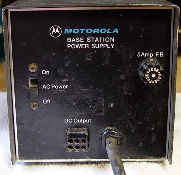
The Motorola TPN1154 is a 14-amp desktop power supply. The Motorola TPN1136 is an 8-amp desktop power supply. The two units are very similar.
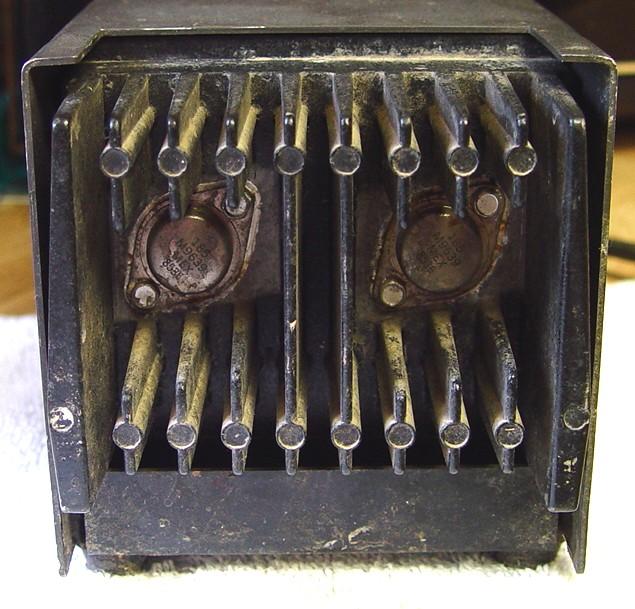
I acquired one of the 14 amp units with three Maxar-80 VHF mobile radios. Here are front and rear photos of this unit.
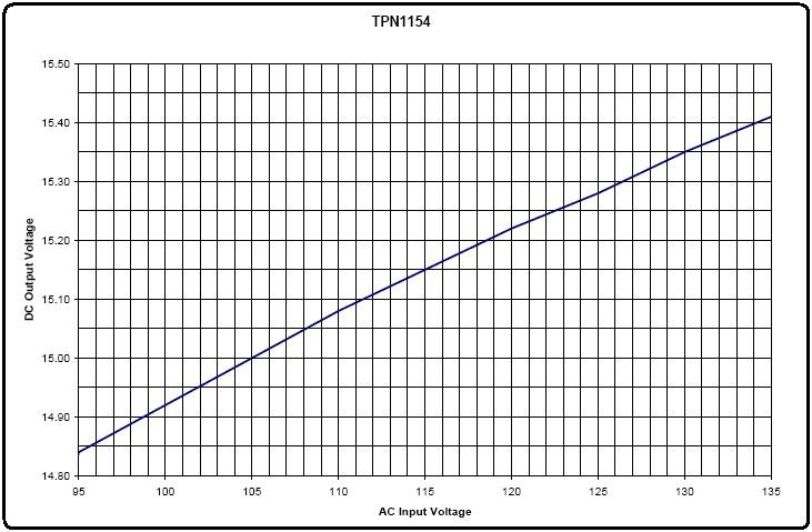
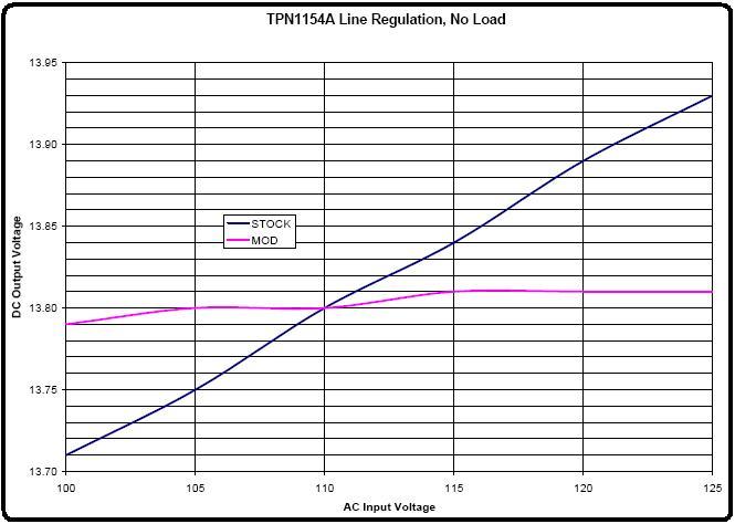
While the supply worked, the regulation was very poor. The regulated output voltage varied as the unregulated DC voltage changed, and that changed as the load current or the incoming AC line voltage was varied. There was no easy fix to the existing circuit that would solve this problem. Eric WB6FLY had already run some load tests on these supplies and mine acted just like his did. The problem is that the unit is designed poorly. The unregulated DC voltage is used to provide power for the regulator circuit and that voltage decreases as the load current increases, so the regulation suffers. Varying the incoming AC line voltage also changes the unregulated DC voltage, so it too has just as much effect on the regulated output voltage. The graph below shows how bad things are.
I did some investigation and noticed that the line regulation spec for the common LM7812 three-terminal regulator is in the order of tens of millivolts, far better than what the Motorola power supply was ever capable of producing. The downside is that these three-terminal regulators are only capable of about 1 amp of current, far less than the Motorola power supply was designed to do.
Studying the data sheet, I think I figured out a way to use an LM7812 regulator in place of most of the original regulator circuitry. I tried to implement this as a drop-in replacement, where the original circuit board is removed and a new one with a few simple parts is installed. The original supply was non-adjustable; I decided to make mine adjustable, at least within about +/- 15% of the nominal 14VDC output. I did all of this for a parts cost of under $7US.
The Original Power Supply:
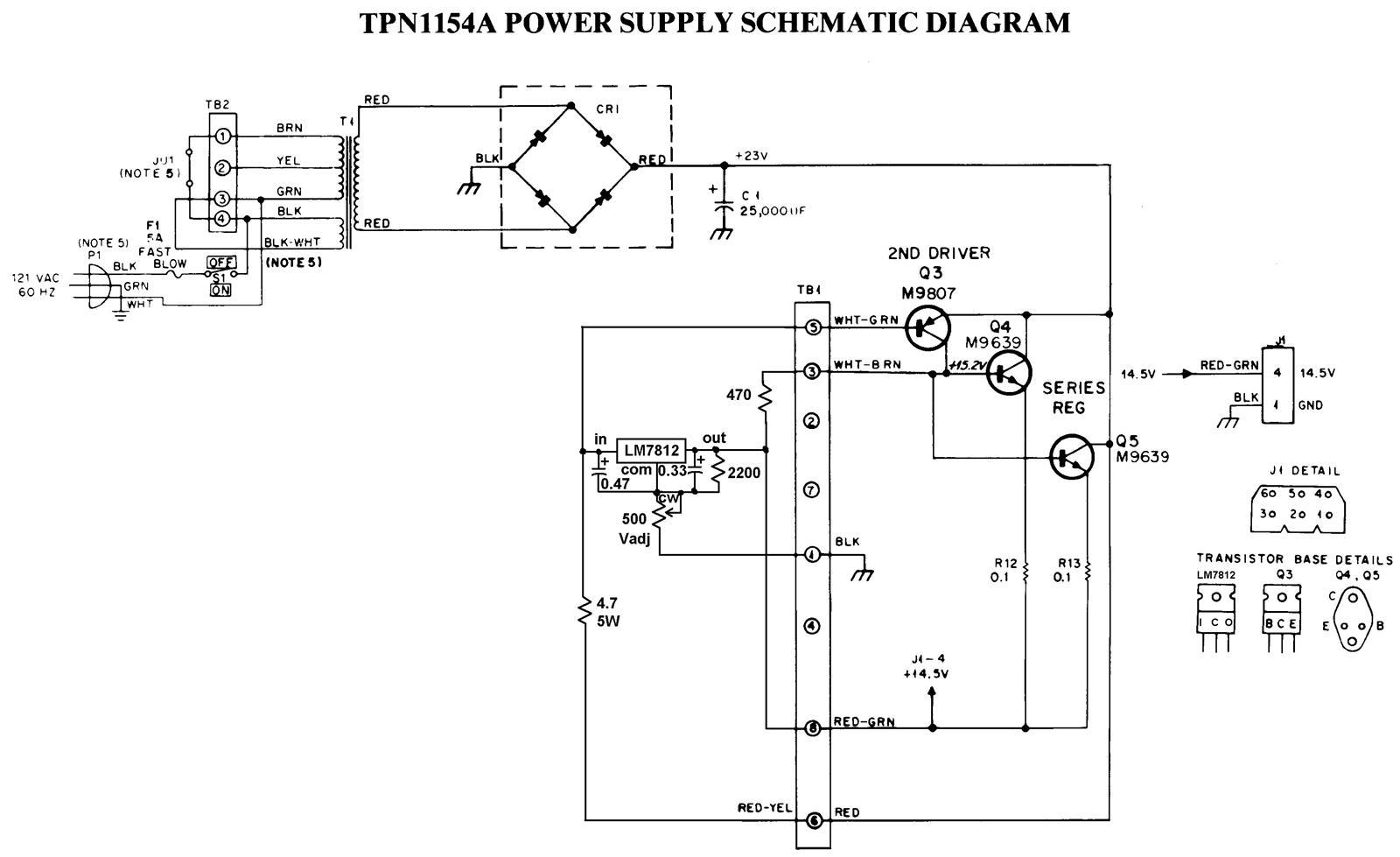
Here's the original schematic of the 14-amp power supply, taken from the Maxar-80 manual. The 8-amp supply has only one series regulator transistor (Q4) that feeds the output directly; it does not have R12 or R13, or Q5 mounted to the heat sink. The regulator circuit board components are shown in the schematic to the left of the terminal strip, in the area surrounded by dotted lines.
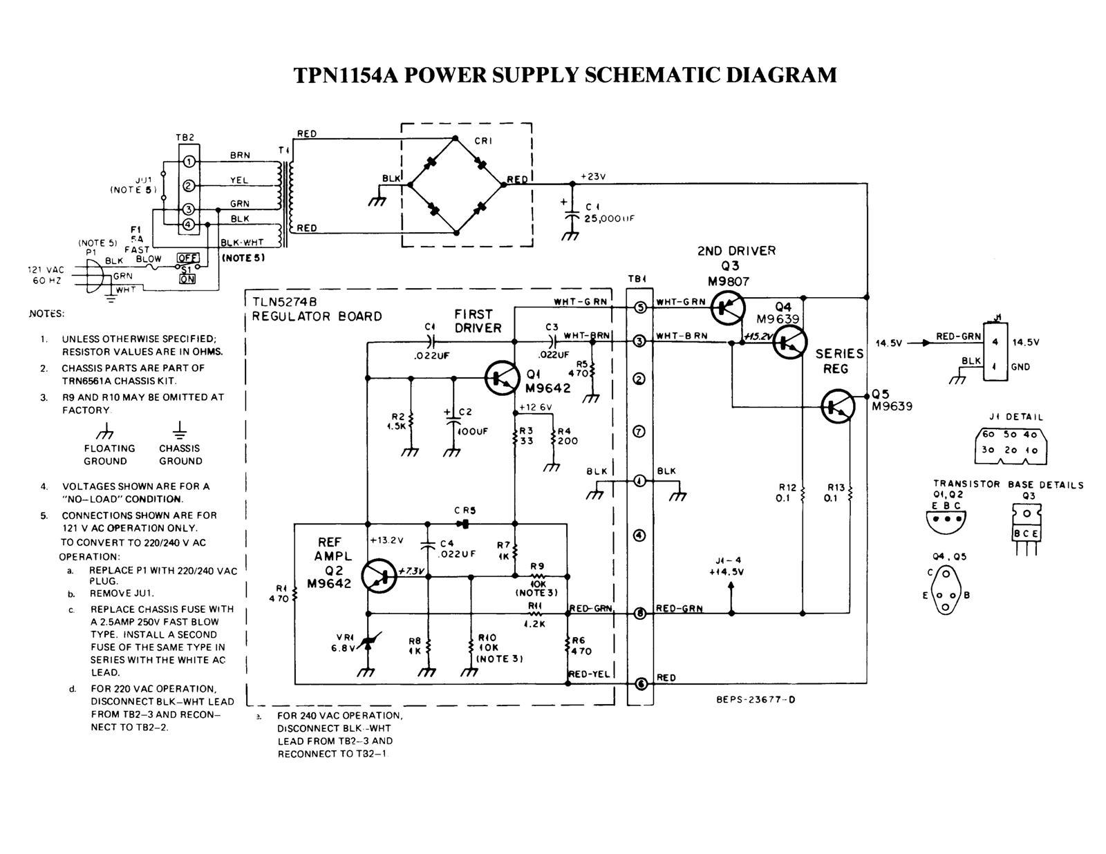
Here's a photo showing the terminal strip and the original regulator circuit board. The terminals are numbered sequentially from 1 to 8, starting at the front of the supply (left side of photo). Lugs 2 and 7 are used to mount the terminal strip, which grounds them. Lug 4 is unused.
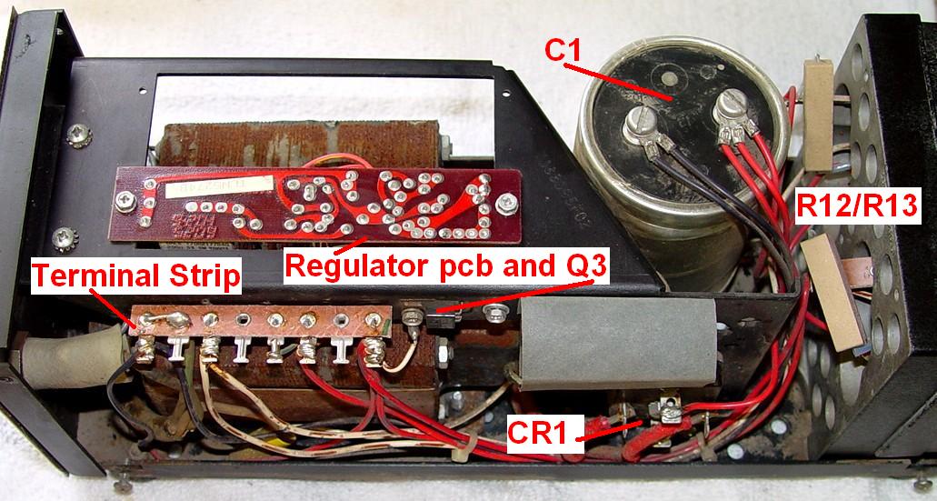
The terminal strip lugs have the following use or function. Note that the Wire Color is the color of the wire that goes from the terminal strip to the regulator circuit board.
| Lug# | Signal or Function | Wire Color |
|---|---|---|
| 1 | Ground | Black |
| 2 | Mounting (Not Used) | |
| 3 | Series Reg Base | White-Brown |
| 4 | Spare (Not Used) | |
| 5 | 2nd Driver Base | White-Green |
| 6 | Unregulated A+ Input | Red-Yellow |
| 7 | Mounting (Not Used) | |
| 8 | Regulated A+ Output | Red-Green |
Theory of Operation (Original Design):
The regulated output voltage enters the regulator circuit board at pin 8. If this voltage is too low, Q2 will draw less current through R1 and its collector voltage will rise. This causes Q1 to draw more current, pulling the base of Q3 lower, causing Q3 to draw more current, which pulls the bases of Q4 and Q5 higher, causing them to pass more current to the load, which causes the voltage at pin 8 to rise. This returns the circuit to equilibrium. If the regulated output voltage rises, Q2 turns on more, Q1 draws less current, Q3 draws less current, Q4 and Q5 pass less current, and the output voltage decreases, restoring equilibrium. Unfortunately the unregulated input voltage that comes into the board at pin 6 also has an effect on the regulated voltage. This can drop because the incoming AC voltage goes lower, or when the load current increases. Thus the current feeding VR1 varies as a function of both the load current and the line voltage; hence the poor regulation.
Modifying the Power Supply:
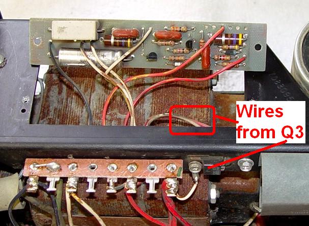
I just unsoldered six wires at the circuit board so I could attach them to the new regulator circuitry. On my unit, Q3 was a TO-220-style transistor but its White-Brown collector lead went to a circuit board pad where the other White-Brown wire coming from the terminal strip was attached, rather than going directly to lug 3 of the terminal strip as implied in the schematic, so I attached the White-Brown wire to lug 3. Leave the other wires going to Q3. See the close-up of Q3, the terminal strip, and the component side of the old circuit board below.
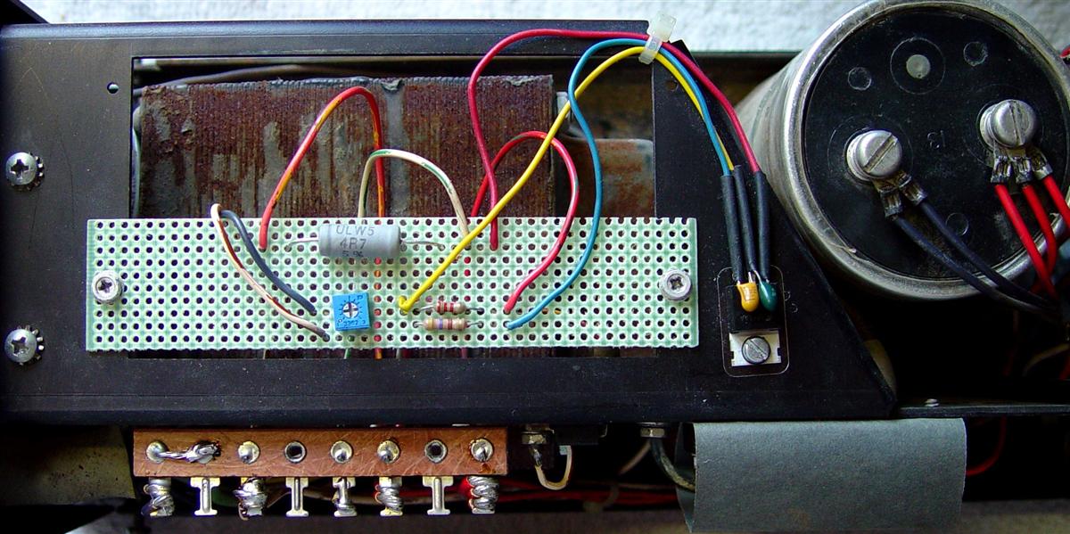
I constructed the new regulator parts on a piece of perforated fiberglass circuit board material cut to the same size as the original circuit board, about 4-3/4 by 1 inch. I used the original mounting holes and hardware. You can use whatever you have or can get, although you may need to be creative in mounting it. I had to drill one #4-40 clearance hole (1/8 inch) to mount the LM7812 to the top of the chassis. It was in line with one edge of the circuit board cutout area and 3/4 inch from the rear edge. See the photo below.
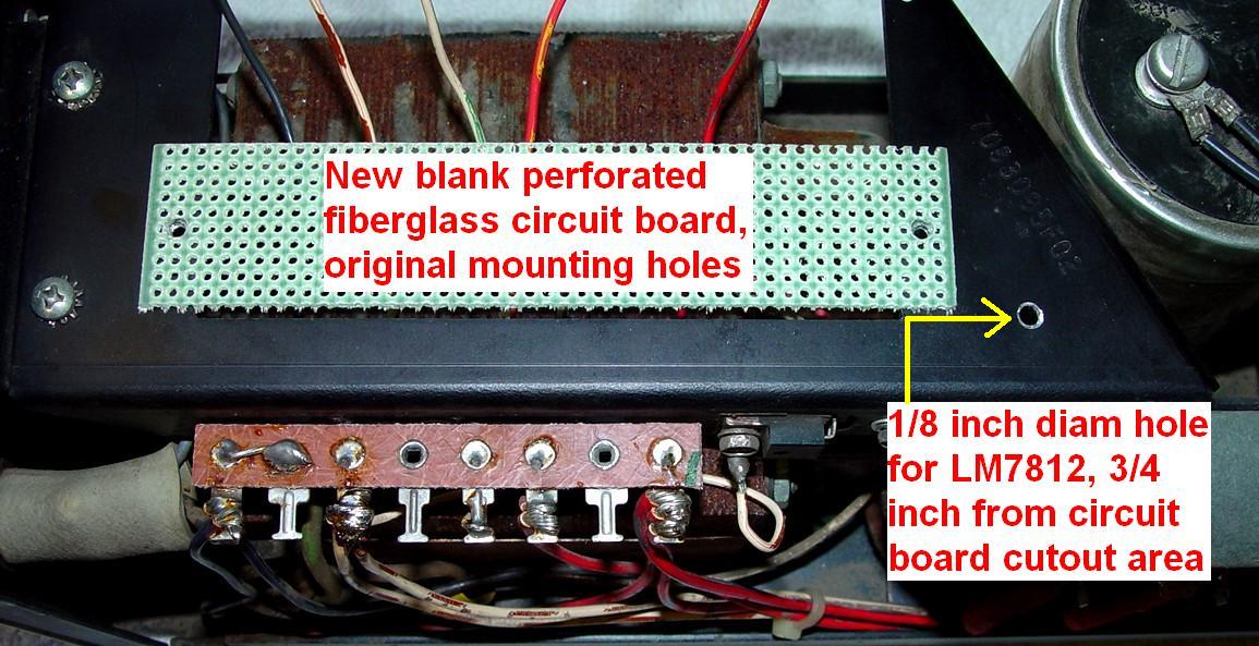
You can also see the five wires coming from the terminal strip after I unsoldered them from the original circuit board; they're in the same order as the lug numbers. From left to right: Black/1, White-Brown/3, White-Green/5, Red-Yellow/6, Red-Green/8.
THE LM7812 MUST BE MOUNTED TO, AND INSULATED FROM, THE CHASSIS. If its case touches ground, you'll only get about 12 volts out of the supply and it won't be adjustable. Parts placement is not critical however you should leave plenty of space around the 4.7 ohm resistor; it's the only part that might get warm. Here's the schematic diagram showing the new regulator circuitry within the dotted lines.
There's over an inch of clearance below the circuit board but only 1/2 inch above it. Connect the five wires coming from the terminal strip lugs to the appropriate spots on the new circuit board. I also elected to extend the leads of the LM7812. Here's a photo of my completed supply:
I could have flipped the circuit board over and mounted it with the components facing down; the wires were long enough. The only issue with that is the pot could not have been adjusted that way. A different style pot would have been required, or I could have mounted it on the other side of the perforated board.
Construction was straightforward; I checked, re-checked, and checked again my wiring. I set the pot to minimum resistance, which produced just under 12VDC output. There was no smoke or other surprises when I turned it on, although I did run it through my Variac just to be safe.
Theory of Operation (New Design):
The new circuit relies on a three-terminal regulator to provide vastly improved immunity to variations in the unregulated DC input voltage, hence improved line regulation. The circuit operation is not entirely intuitive though. Voltage regulation is provided by the LM7812 and I won't go into how that works. The regulated output power is supplied through two paths: out of the LM7812 via pin 8, and through Q3, Q4, and Q5, which also feed pin 8. At low load currents (under about 0.15A), the unregulated DC input goes through the 4.7 ohm resistor and the LM7812 to feed the load on pin 8. As the load current increases, the voltage drop across the 4.7 ohm resistor increases. Q3 will begin to turn on when this drop approaches 0.7V. When it does, Q3 starts supplying current to Q4 and Q5, and they begin to supply current to the load. This continues up to the maximum rated load current. The LM7812 never has to supply more than about 0.2A of current.
The Results:
The output voltage regulation was vastly improved and I would say it's near perfect. Measured at the terminal strip, it doesn't vary more than 25 millivolts as the load or input voltage changes. Initially there was an issue with regulation at no load; I discovered the LM7812 was oscillating so I soldered a small tantalum capacitor (pale orange) directly across the output and ground terminals of the device; that cured the problem. Most data sheets suggest these capacitors and I usually automatically install them, but for some reason I didn't initially plan for one. Luckily it's very easy to add one. I used small diameter heat-shrink tubing over all three leads but never actually shrank it, so it can be slid off if needed.
I sent the redesigned supply to Eric WB6FLY for load tests. When he got it, his readings were quite different from mine. He still saw oscillations on the output voltage, so he added a small tantalum capacitor (dark blue) across the input and ground terminals of the LM7812 and that cured the problem. It's shown in the new schematic diagram and parts list.
Line regulation is the change of output (DC) voltage with a change of input (AC) voltage. Here is the data from the original TPN1154A power supply that has been adjusted for a nominal 13.9 VDC output:
| Load Cur. | Input AC Voltage | |||||
|---|---|---|---|---|---|---|
| 100 V | 105 V | 110 V | 115 V | 120 V | 125 V | |
| 0 A | 13.71 | 13.75 | 13.80 | 13.84 | 13.89 | 13.93 |
| 5 A | 13.42 | 13.50 | 13.56 | 13.62 | 13.66 | 13.70 |
| 10 A | 12.90 | 13.26 | 13.35 | 13.42 | 13.47 | 13.51 |
| 15 A | 11.69 | 12.55 | 13.11 | 13.20 | 13.27 | 13.32 |
| 20 A | 10.26 | 11.19 | 12.09 | 12.85 | 13.07 | 13.14 |
Note that the supplies probably aren't rated for more than 15 amps of load and at 100 VAC input the unregulated DC voltage is too low to let the regulator circuit operate. My modified power supply did marginally better:
| Load Cur. | Input AC Voltage | |||||
|---|---|---|---|---|---|---|
| 100 V | 105 V | 110 V | 115 V | 120 V | 125 V | |
| 0 A | 13.79 | 13.80 | 13.80 | 13.81 | 13.81 | 13.81 |
| 5 A | 13.65 | 13.65 | 13.66 | 13.66 | 13.67 | 13.67 |
| 10 A | 13.31 | 13.53 | 13.53 | 13.53 | 13.53 | 13.53 |
| 15 A | 12.33 | 12.99 | 13.32 | 13.39 | 13.40 | 13.41 |
| 20 A | 11.12 | 11.91 | 12.61 | 13.02 | 13.22 | 13.24 |
It looks a lot better graphically. This is the no-load variation: 200mV vs 20mV over the range listed above.
Eric's very thorough and complete DC load test results are available as small 32kB
PDF files.
Here are the results of the stock TPN1154A power
supply.
Here are the results of my modified TPN1154A power supply.
Most of the data for the two supplies was not different enough to report, but my modified
supply did just slightly better.
Parts List:
I purchased the parts from Digikey, mainly because I had to get some other stuff that Mouser didn't have. Almost any supply house will have these; none are really critical.
| Digikey Part # | Description | Price |
|---|---|---|
| LM7812ACT-ND | 3-terminal 12V regulator | $0.69 |
| 4724K-ND | TO-220 mounting hardware kit | $1.90 |
| 399-3538-ND | 0.33uF 35V tantalum capacitor | $1.06 |
| 399-3617-ND | 0.47uF 35V tantalum capacitor | $1.06 |
| CF12JT470RCT-ND | 470 ohm 1/2w carbon film resistor | $0.14 |
| CF12JT2K20CT-ND | 2200 ohm 1/2w carbon film resistor | $0.14 |
| 3362P-501LF-ND | 500 ohm 1/2w trim pot | $1.05 |
| 985-1012-1-ND | 4.7 ohm 5w resistor | $0.42 |
The total cost for the above parts is $6.46US.
By the way, the mating DC output connector is Molex part # 03-09-2062, and the 14-20 gauge pins are Molex part # 02-09-2103. Mouser part numbers are 538-03-09-2062 and 538-02-09-2103.
Acknowledgements and Credits:
Maxar-80 is probably trademarked by Motorola, Inc.
Eric WB6FLY was kind enough to run load tests on my modified power supply. He had already run the same tests on his original supply. Those can be found in the parent article.
Contact Information:
The author can be contacted at: his-callsign [ at ] comcast [ dot ] net.
Back to the top of the page
Up one level (Motorola index)
Back to Home
This page originally posted on Monday 09-Jul-2012.
This web page, this web site, the information presented in and on its pages and in these modifications and conversions is © Copyrighted 1995 and (date of last update) by Kevin Custer W3KKC and multiple originating authors. All Rights Reserved, including that of paper and web publication elsewhere.