Back to Home
for the Motorola
MaraTrac Mobile Radio
By Robert W. Meister WA1MIK
and David W. Malicki N1OFJ

|
MaraTrac index Back to Home |
Manual Power Control for the Motorola MaraTrac Mobile Radio By Robert W. Meister WA1MIK and David W. Malicki N1OFJ |
|
Background:
Dave acquired a 29.7-36 MHz MaraTrac that he wanted to use on 29.6 MHz. It programmed right up (after hex-editing the software) but the output power was erratic. We were discussing this and the idea of manual power control came up. Both of us had seen and dealt with this problem on MaxTrac radios. How hard could it be to make the same modification to a MaraTrac?
The MaraTrac and M400 radios have the same lack of power control problem that the MaxTrac and Radius radios suffer from: when operating above or below their intended frequency range (band split), the output power is uncontrolled and can be anything from 1 watt to over 150 watts. Some radios are worse than others. The fix is the same: add a manual power control adjustment. This same modification can be done on any MaraTrac radio (UHF or VHF) so it operates a bit better out of its normal operating range. They all use the same logic board.
If you are new to manual power control, now might be a good time to learn a bit more about it. Click here to read the article for the MaxTrac radios then continue reading about the MaraTrac version.
What We'll Be Doing:
The MaraTrac uses a logic board that's just about identical to the MaxTrac HLN5172 or HLN5173; same circuitry but a couple of parts are different or missing because the MaraTrac has an external audio amplifier that drives the loudspeaker. The schematic below details the modification. Click on any of the images for a larger view.
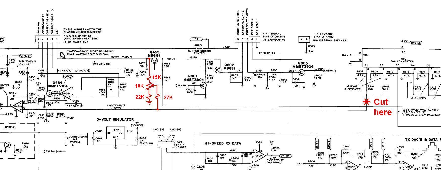
The four resistors attached to U801 pins 2 and 4: R808, R809, R810, and R811, are all on the other side of the logic board, under U801. The junction conveniently comes back to the top of the board as a trace between U801 pins 8 and 9, making it very accessible.
You should verify that the radio works properly on frequencies appropriate for the band the radio was manufactured for, before doing this modification. All work can be performed on the radio without removing any boards.
What You Will Need:
I've already done the analysis and experimentation. You will need the following
parts:
Modifying The Radio:
Disconnect the control cable and the antenna and remove the radio from the vehicle. Turn the radio over and remove the bottom plate with a Torx T-15 driver to access the logic board. To make access a bit easier, unplug the 5-pin connector going to the exciter board and the 14-pin connector going to the front interconnection board.
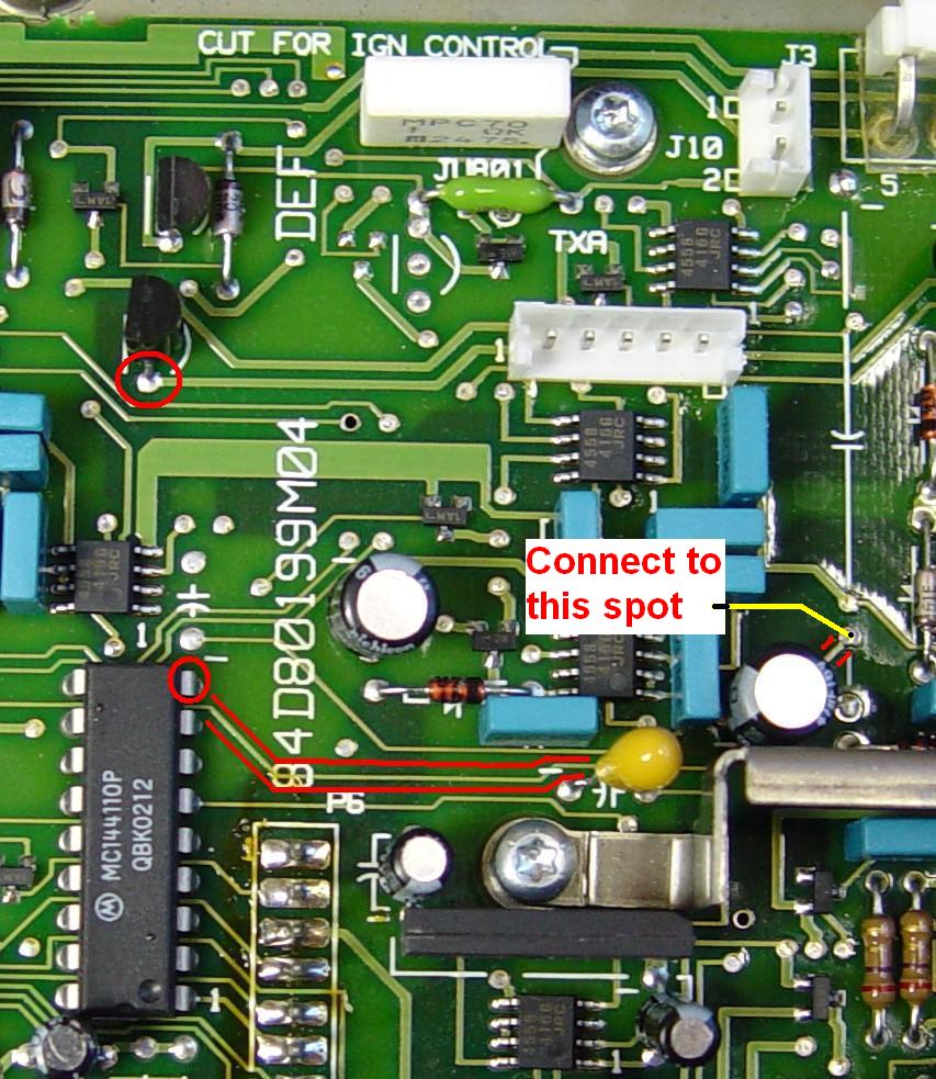
The microprocessor controls the transmitter's output power by varying the voltages coming out of U801, pins 2 and 4. You need to disconnect this circuit and add your own manual adjustment in place of U801. Locate the foil to be cut; it's outlined in the photo below. I'd recommend cutting it close to U801, the 18-pin digital-to-analog converter (DAC) integrated circuit. A sharp knife or even small diagonal cutters can chop right through that foil. Just make sure it's completely cut. If it isn't, the manual power control will fight with the radio's built-in power control and the results will be unpredictable. Leave some trace visible so you can bridge it with a wire in the future if you ever want to remove the manual power control components and put the radio back to stock.
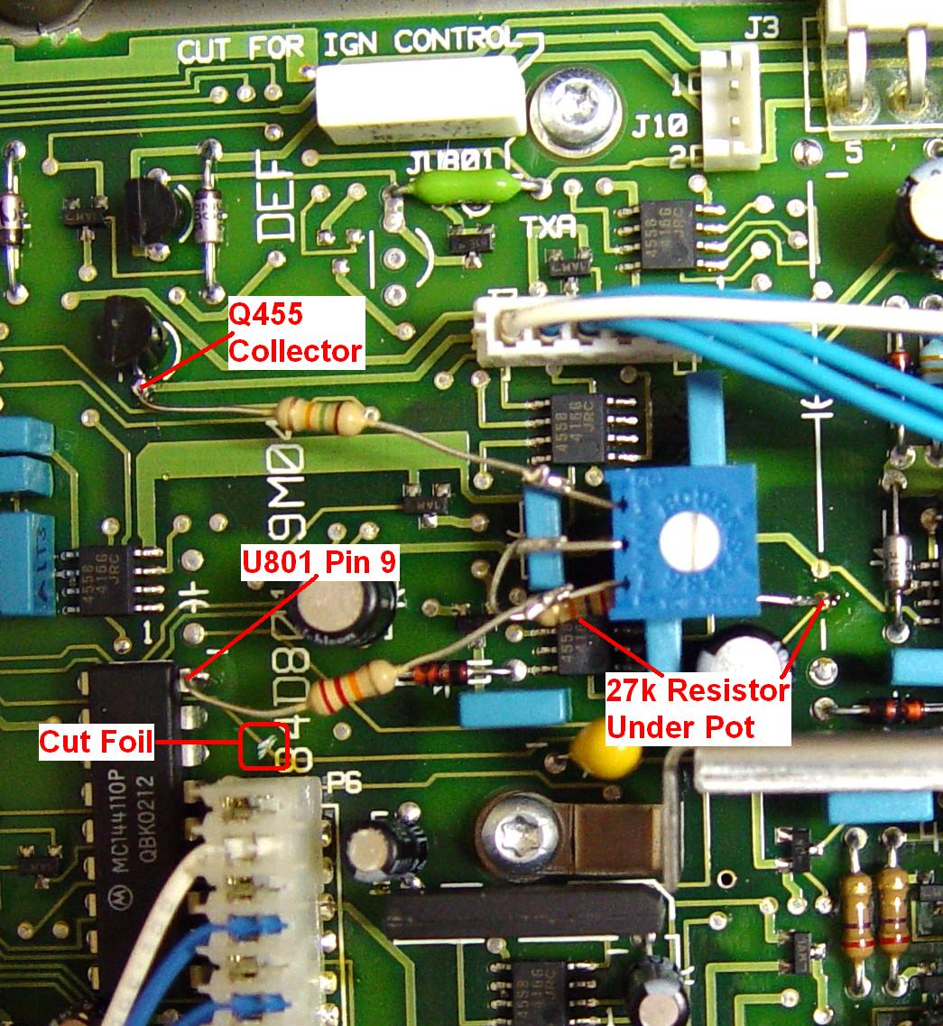
The 10k pot can be glued to the top of the blue capacitors just above the stiffening bracket to the right of U801. I'd recommend a pot such as the Bourns 3386X series, a 3/8 inch single-turn square pot with an easily accessible screwdriver slot for adjustment and leads coming off one side. Place the pot in position and orient the leads so they point to the left. You can then attach the other parts directly between the pot and the other points indicated in the photos and diagrams. I put the 27k resistor under the pot because the leads weren't long enough to place it around the side.
The values of the resistors have been chosen to limit the power adjustability range to 45-135 watts on a low-band radio. You may have to change the values of the upper and lower fixed resistors to alter this range.
The 15k resistor goes from the upper end of the pot, to Q455's collector. Increase this value if you want a lower maximum power value. Q455 is located directly above U801 and the collector lead is the one closest to U801. This point is circled in red. A foil runs from this lead to the 5-pin connector socket to its right. By using switched 9.6V, the power control circuitry will be disabled in receive.
The 22k resistor goes from the lower end of the pot to ground. Reduce this value if you want a lower minimum power value. A convenient spot is pin 9 of U801. This point is circled in red.
The 27K resistor going to the arm of the pot has to go to the circuitry after the cut in the circuit board. A convenient spot is the feed-through hole at the end of the trace you cut earlier, just above the stiffening bracket, under the spot where a 1000uF capacitor used to be (this is present on the MaxTrac but is removed for the MaraTrac). This spot is marked on the picture above; just follow the red outlined foil all the way to the right and you'll see the solder-filled hole. The X-ray view below shows this location a bit better. All the connection points are indicated with green circles and the foil to be cut has a green line on top of it.

I have installed the parts and tested the radio and the manual power control. It works fine. I have not yet adhered the pot to the blue capacitors that it's resting on top of. Here's a photo of the completed radio, showing the attachment points, cut foil, and all components.
Adjustment:
Reinstall the two cables and put the radio back into service with a wattmeter attached to the antenna connector. Set the pot to the middle of its range. With the mike keyed, adjust the pot for the desired output power on the out-of-band frequencies the radio will be operated at. It might also be useful to turn the power level in RSS down to a low level, such as a setting of 50-60, so the microprocessor doesn't try to do anything nasty to the radio if it ever realizes it's no longer in control. Reinstall the bottom cover and place the radio back in service.
Oh, it turns out that Dave's radio actually worked fine on 29.6 MHz; he had a bad RF cable going from the wattmeter to the dummy load, and at high power this was causing the power indication to go nuts. He replaced the cable and the stock radio is now rock-solid on 10 meters and it doesn't need a manual power control pot. But at least we now have a method and an article on how to deal with this problem in the future, so not all is lost.
Another Experience:
Mark KC8QVX wanted a bit more adjustability on his MaraTrac, so he used slightly different resistor values but achieved a power range of 35 to 125 watts. He mounted a much larger pot on the casting next to the logic board, behind the antenna relay, and put a knob on it and labeled it to indicate that this controlled the output power. He supplied both photos below.
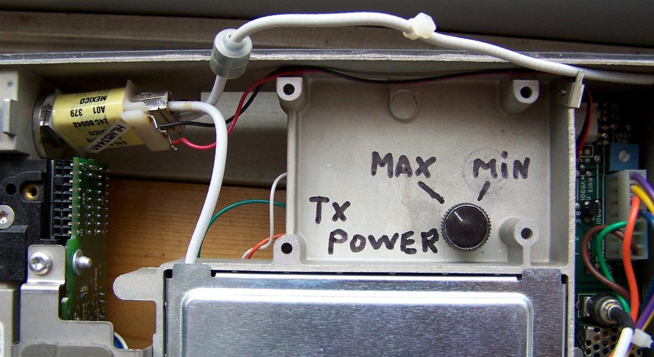
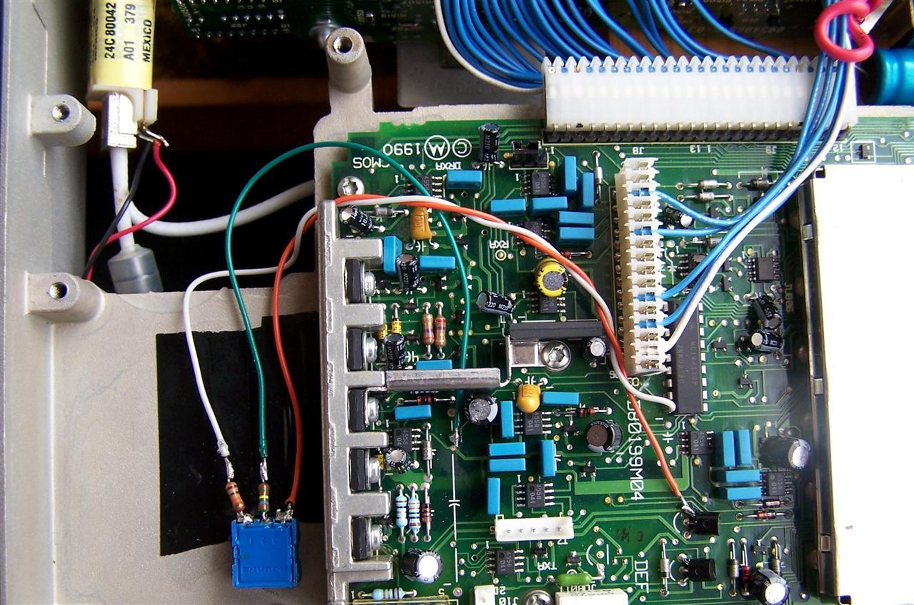
He used a 10k pot, a 27.4k resistor in series with the arm of the pot, and a 10.9k resistor on the low end of the pot to ground. The high end of the pot connects directly to the Transmit 9.6V (Q455 collector). The photo below shows his actual wiring.
Contact Information:
Bob can be contacted at: his-callsign [ at ] comcast [ dot ] net.
Dave can be contacted at: his-callsign [ at ] hotmail [ dot ] com.
Back to the top of the page
Up one level (MaraTrac index)
Back to Home
This article was conceived October 7, 2011.
Article text, photos, artistic layout, and hand-coded HTML © Copyright 2011 by Robert W. Meister WA1MIK and David W. Malicki N1OFJ.
This web page, this web site, the information presented in and on its pages and in these modifications and conversions is © Copyrighted 1995 and (date of last update) by Kevin Custer W3KKC and multiple originating authors. All Rights Reserved, including that of paper and web publication elsewhere.