Motorola index
Back to Home
and Radius Mobile Radios
for Manual RF Power
Adjustment/Control
By Robert W. Meister WA1MIK
|
Maxtrac Index Motorola index Back to Home |
Modifying the MaxTrac and Radius Mobile Radios for Manual RF Power Adjustment/Control By Robert W. Meister WA1MIK |
|
Background:
A while back I decided to see if I could put up a 900 MHz repeater. I started gathering the necessary pieces of equipment. My backup 445 MHz repeater had the enclosure, power supply, and controller, so I just needed a pair of radios, a duplexer, and an antenna. I bought a duplexer on eBay and obtained a vertical antenna, a converted 800 MHz MaxTrac (D25-series) for use as the receiver, and a converted 900 MHz MaxTrac (D27-series) for use as the transmitter. I chose an empty frequency pair of 902.4125 MHz input, 927.4125 MHz output, both with 100.0 Hz PL.
What I Started With:
I began by programming the frequencies and PL tones on both radios with the appropriate RSS package. Unfortunately, after modification, both radios were incapable of transmitting on their original frequency ranges. At 927 MHz, the transmitter was putting out over 25 watts, and the power control settings had absolutely no effect on the output power. The alignment screens tried to make the radio transmit in the 896-902 and 936-941 MHz bands, however the VCO modifications had already moved the active range of the radio to the 923-929 MHz, so the RF power control routine in the firmware threw up it's hands and gave up resulting in the transmitter running wide open. As this was only a 12-watt radio putting out over twice its rated power, I knew I needed to do something to lower the output power, and FAST!
Radio Analysis:
I started doing some research on controlling the power of MaxTrac radios under this situation. I found information about it on Repeater-Builder and other web sites, but the best one was found at the Sierra Repeater Association, K6SRA. It had pictures and a description of adding a manual power control adjustment. Armed with the service manual, I figured out exactly what was being done.
The transmitter's output power is controlled by a DC voltage that, according to the service manual schematic, ranges from 4 to 7 volts during transmit, and rests at 0.1 volts during receive. This voltage is developed by two digital-to-analog (D/A) converter outputs on the logic board (U801 pins 2 and 4). Other D/A outputs control deviation and frequency, and enable/disable Hear-Clear (companding) on 900 MHz radios. The K6SRA modification replaces the signal generated by the D/A converter through R810 and R811 (that feeds the control line labeled "TX POWER ADJUST"), with a variable voltage generated from the wiper of a potentiometer, which gives the user full manual control of the output power. This pot runs from ground to a source of 9.6 volts on transmit. Note that the component references are the same on all MaxTrac logic boards (VHF, UHF, 800 MHz, and 900 MHz).
Comments About This Modification:
Note that this mod only changes the source of the transmitter power control voltage; the rest of the PA deck has to properly respond to this voltage.
It's been said in many other articles on this web site, but bears repeating: Make sure that you have a properly working radio before you start modifying it. If it's a crystal controlled radio, try to acquire it with the crystals / channel elements / ICOMs. If it's a programmable radio (like a MaxTrac) and it comes erased, reprogram it on the previous frequencies (or near them). Either way, test the radio for receiver sensitivity, transmitter power, and a clean transmitter before you pick up the wire cutters or soldering iron. No sense modifying a radio and having it not work properly, because you won't know if the problem is in the original radio or in the modification.
That said, the original modification that started my journey has the following benefits:
Having said that, there are a few things that I wasn't happy with:
Taking Measurements:
I decided I could improve upon the technique a bit, and did some preliminary tests using a pair of unmodified 450 MHz radios as test platforms. I connected the radio to a wattmeter and dummy load; power was supplied by an Astron RS-12M power supply. I used a Fluke 189 DMM to measure the control voltage at the junction of R810 and R811, which is the sum of the output of the two D/A signals. I used the Astron's front panel meter to measure the supply current.
Using the output power adjustment screen on RSS, I started at zero, pressed F6 to cause the radio to transmit, took my readings, pressed F6 again to stop transmitting, bumped the value up by 10, and repeated this process until I hit the maximum value. The results are summarized in the table below. Note that the last three readings for the UHF radio are identical; originally I thought this was because the power supply went into current limiting, but further testing proved that the radio had reached its limit. If you want to experiment like this yourself, don't let the radio transmit for more than a few seconds at a time with power levels higher than 90 on the RSS screen.
| D34LRA7PA5AK (25 watt UHF) | D44MJA7DA5AK (45 watt UHF) | |||||
|---|---|---|---|---|---|---|
| Tuning Value RSS | Output Power Watts |
Control Voltage DCV | Input Current DCA |
Output Power Watts | Control Voltage DCV |
Input Current DCA |
| 0 | 0.00 | 1.138 | 0.5 | 0.00 | 1.154 | 0.5 |
| 10 | 0.00 | 1.335 | 0.5 | 0.00 | 1.598 | 0.5 |
| 20 | 0.00 | 1.850 | 0.5 | 0.00 | 2.131 | 0.5 |
| 30 | 0.00 | 2.380 | 0.5 | 0.54 | 2.659 | 1.5 |
| 40 | 1.72 | 2.908 | 2.0 | 4.74 | 3.196 | 2.8 |
| 50 | 5.88 | 3.440 | 2.9 | 12.32 | 3.735 | 4.0 |
| 60 | 12.25 | 3.977 | 3.8 | 22.00 | 4.238 | 5.2 |
| 70 | 20.10 | 4.500 | 4.5 | 35.00 | 4.774 | 6.5 |
| 74 | 23.50 | 4.711 | 5.0 | 44.70 | 5.146 | 7.5 |
| 80 | 28.60 | 5.029 | 5.5 | 48.00 | 5.311 | 8.0 |
| 90 | 35.90 | 5.566 | 6.5 | 57.00 | 5.839 | 9.8 |
| 100 | 41.20 | 6.088 | 7.5 | 70.00 | 6.366 | 11.5 |
| 110 | 45.20 | 6.662 | 9.0 | 70.00 | 6.900 | 11.5 |
| 120 | 47.50 | 7.147 | 9.6 | 70.00 | 7.114 | 11.5 |
Control Voltage Range:
The results of these tests showed that the usable control voltage range is about 2 to 6 volts, corresponding to RSS values of 25-95. Typically these radios put out rated power at RSS values of 70-80, which is equivalent to about 5 volts on the control line. The original circuit, with the pot running from ground to 9.6 volts, would have given me a dead band at the low end, and could have allowed the output power to reach dangerous levels at the high end, so I decided to limit the controllable range. The end result is a circuit that affords safety while providing adequate control over a reasonable power range. I chose my component values to give me a control voltage range of 2.4 to 6.0 volts.
Components:
I selected fixed resistors and a potentiometer to give me the voltage range I wanted. This ended up being a 6.8k resistor on the low side, a 10k 25-turn potentiometer, and a 10k resistor on the high side. I also used a 27k resistor in series with the arm of the pot, which duplicates the original R810 and R811 components. The pots were NTE part 500-0224, which seems to be a pair of individual NTE part 64X-103. They are about 7/16 inch square and have the name "Spectrol" on them. The pair cost me $3.97 from a local parts store; I'm sure something similar can be bought from Jameco or Mouser. I used a dab of Super Glue and stuck it to an otherwise empty area of the logic board, near the D/A converter. The resistors were soldered in place using insulating sleeving where necessary.
Modifying the Radio:
There's always more than one way to accomplish any task. The idea is to disconnect the D/A output from the power control circuit, and control the voltage manually. One method actually removes both R810 and R811. On the newer logic boards, these are surface-mount resistors on top of the board, very close to the D/A converter chip. Of course, once removed, they're easily lost and, should you ever decide to return the radio back to its original condition, they're not easy to replace. I chose to leave the components in place and make a small cut on the circuit board trace where the two resistors connect to a pad that goes to the rest of the power control circuitry. A couple of cuts with a sharp knife, and some scraping, did the trick. This left me with a convenient feed-through hole into which I could solder a resistor lead. The cut foil is easy to repair if/when necessary.
Making the Connections:
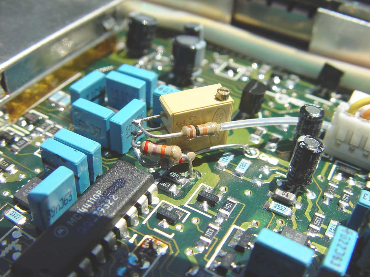
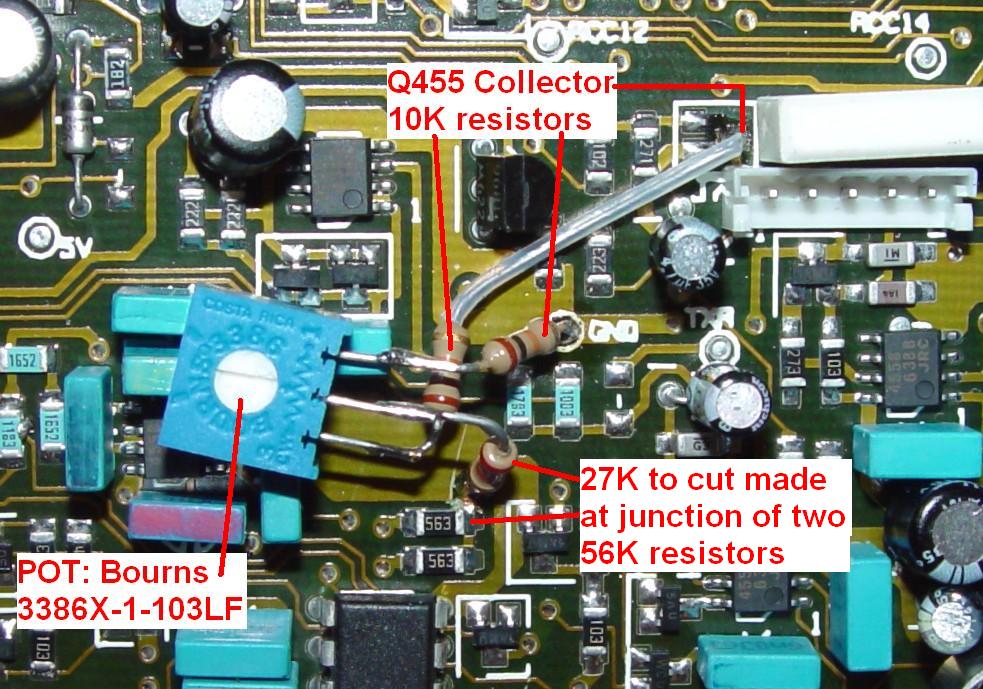
After gluing the 10k pot to the logic board, I ran the 6.8k resistor from a nearby ground foil to the low (counterclockwise rotation) end of the pot. I added the 27k resistor from the feed-through that used to connect to the junction of R810 and R811 to the arm of the pot. The final 10k resistor goes from the high (clockwise rotation) end of the pot, through some sleeving, to a source of 9.6 volts in transmit. This comes from the collector of transistor Q455 that supplies this voltage to pin 1 of the power amplifier connector. See Photos 1 and 2, and Schematics 1 and 2 below.
Photo 1 shows the 10k pot glued to the logic board and the three resistors that form the circuit. From top to bottom: 10k, 27k, 6.8k. You can barely see the cut in the foil that was made next to the lead of the 27k resistor.
Schematic 1 shows the D/A converter circuitry. X indicates the spot that needs to be cut. The new components are in red
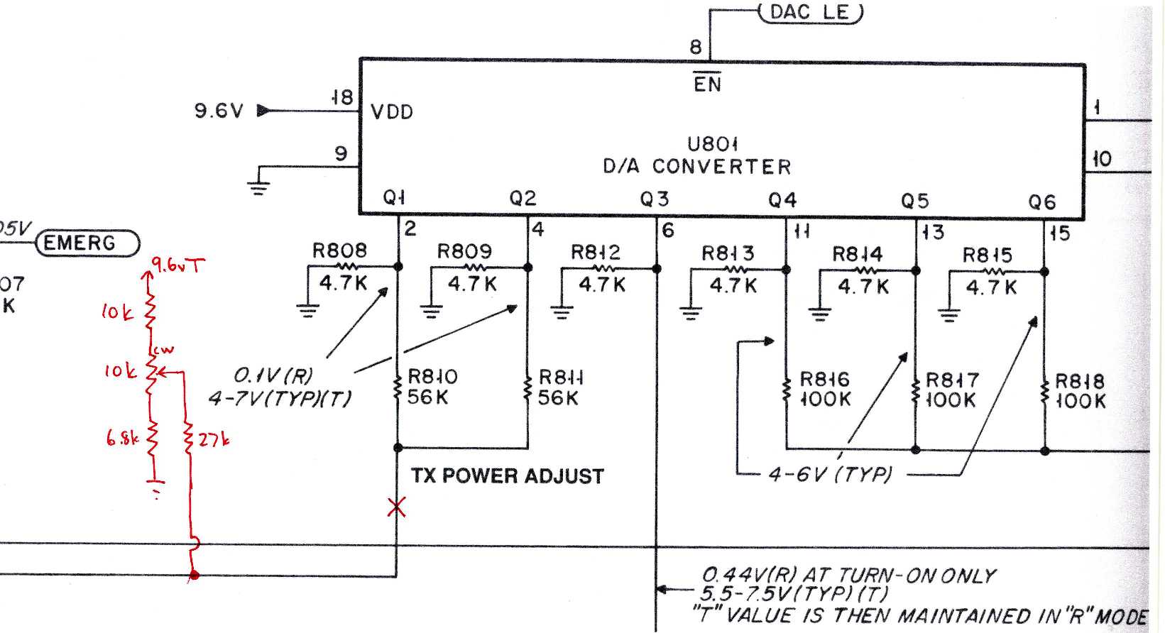
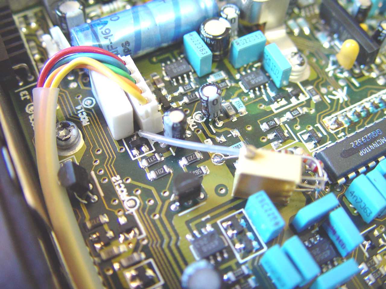
Photo 2 shows the connection to the collector of Q455 which supplies 9.6 volts on transmit. The yellow lead is pin 1 of J7 that feeds the power amplifier.
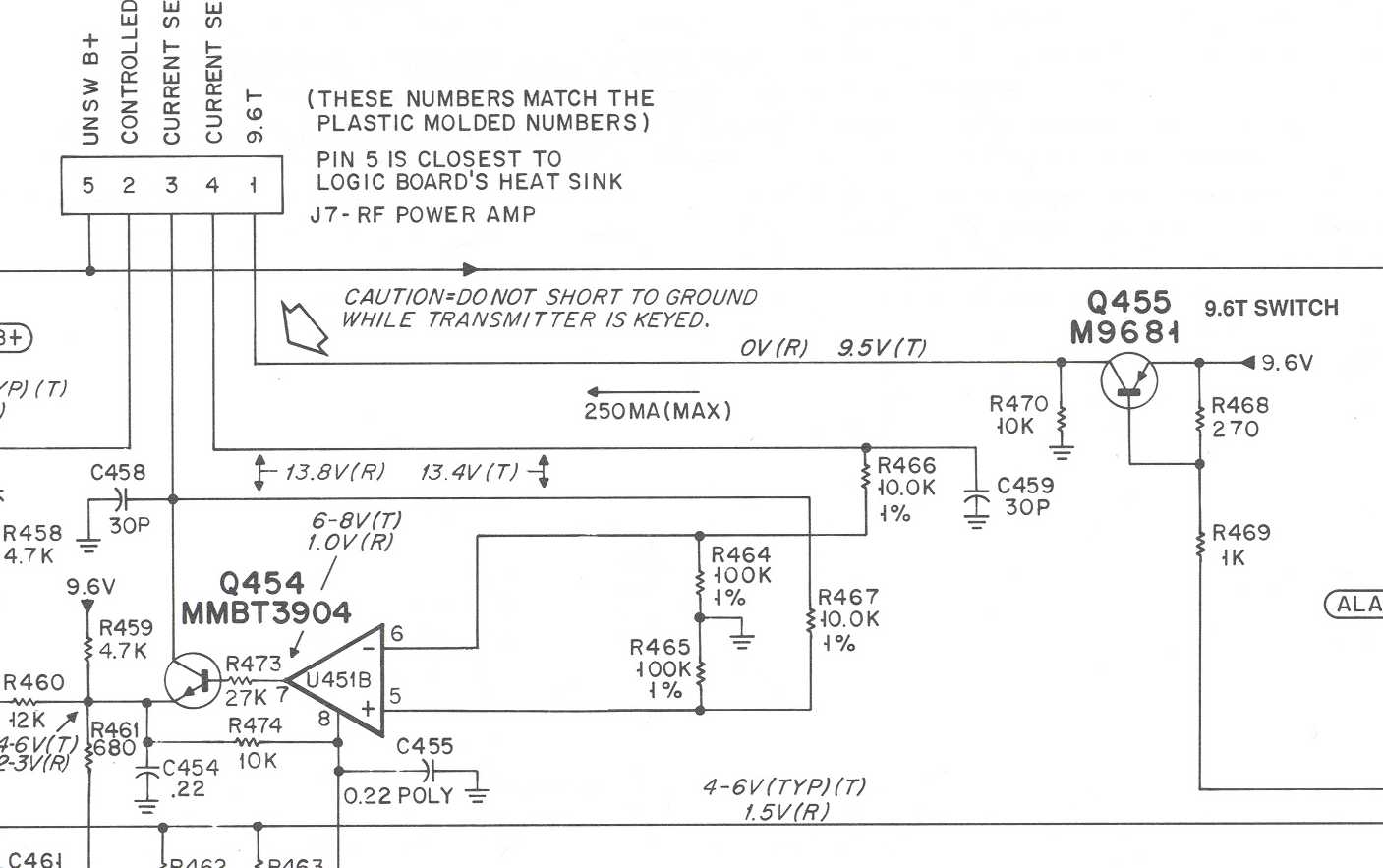
Schematic 2 shows the 9.6 volt source on J7 pin 1 that feeds the power amplifier on transmit. This is the point with the big arrow that cautions you not to short it to ground.
The Results:
While all my tests were done with unmodified 450-470 MHz MaxTracs, the radio I really needed this for was a 900 MHz MaxTrac. After modifying this radio with the power adjustment control components, I turned the pot all the way counter-clockwise, turned the radio on, and took some measurements to see how it actually worked. At the low end of the pot I got 0.25 watts output and 1.5 amps of current. At the high end of the pot I got 17.6 watts output and 5.0 amps of current. I set the power to 12.0 watts and 4.3 amps of current. The power is very adjustable and stable at all settings of the pot, which is not necessarily the case on an unmodified radio at low power levels. The pot is immediately visible and accessible, once the lower cover has been removed. If you needed access to the pot more often, it would be quite easy to drill a 1/4-inch hole in the bottom cover, through which you could stick a small screwdriver or plastic alignment tool. In fact I have done this on a few other MaxTracs.
I subsequently acquired another 12 watt 900 MHz trunking MaxTrac and converted it to a conventional radio. Part of this process requires initializing and aligning the radio, so I knew I had a good base to start with. I didn't have any more 10k pots, but I did have a 1k single-turn pot, so I used that. I scaled the other resistors down by a factor of 10, using a 680 ohm resistor to ground and a 1.1k resistor to the switched 9.6V source. The 27k resistor remained the same. While I didn't measure the low and high power values, I could easily set the output power to 12 watts, and it wasn't far from the center of the pot's rotation. A multi-turn pot is nice, but it's over-kill. I side-mounted the new pot, so it's not quite as easy to get to. Luckily, you don't have to adjust the power very often, so I didn't worry about it.
Later on I acquired a 30 watt 900 MHz MaxTrac, which I promptly blanked and initialized as a conventional radio. I performed a full alignment and it met specifications on the tuning frequencies, but (as with all MaxTracs) the output power was 10 watts on some channels, 30 on others, and even went over 30 watts on one or two frequencies. I took some measurements (similar to those in the two tables above) and determined that the radio was capable of making as little as 6 watts (at an RSS setting of 32) and as much as 42 watts (at an RSS setting of 87; my power supply went into current limiting above that). I played with a few resistor values and ended up with an 11k resistor at the top of the pot, a 10k pot, and a 10k resistor from the bottom of the pot. (I chose these values because they were the first ones I saw in my parts bin and I didn't remember what values I had used before. I should have read this article first!) This let me adjust the power between 12 and 40 watts. I left it at 30 watts and the radio draws 8 amps at this level. The power varies very slightly (maybe 1 watt) between the lowest and highest frequencies programmed into the radio: 902.4125 MHz and 927.6000 MHz. The stock radio is rated for lower power on the talk-around frequencies anyway.
I acquired yet another 30 watt 900 MHz radio. I had bought some other 10k pots and used a pair of 10k resistors at each end of the pot and a 27k resistor from the arm of the pot. I also measured the leads; these pots seem to operate opposite from what I'd expect. In other words, when turned fully counter-clockwise, the center (arm) lead has a low resistance to the lead at the right of the pot. I don't know how the pots are manufactured but this explains why the last radio I modified would increase output power when the pot was turned counter-clockwise. So this time, I took that odd operation into account and wired the clockwise (left) lead to 9.6V and the other (right) end to ground. Now the pot increases the output power when turned clockwise (the expected operation). The pot adjusts the power from 14 watts to 40 watts; I left it centered at 25 watts.
The Bourns 3386X pots were bought at Mouser; their part number is 652-3386X-1-103LF. I mounted it with some Super Glue on top of three nearby blue capacitors. This provides a stable mounting surface but still allows the pot to be removed if necessary. The photo below shows this pot mounted and wired:
Those of you who are using MaxTracs or Radiuses for repeater transmitters know all too well that the radio will try to protect itself if you keep it in transmit mode for 45 minutes or so. It lowers the output power, eventually to zero, even though you have adequate cooling air. I performed this same modification on my backup repeater transmitter to prevent this from happening again. I used the same pot and parts as in the previous paragraph, mounted the pot flat on the logic board (this was an HLE9123A "masked" board), and drilled a 3/16 inch hole through the plastic cover. I can now adjust the power from 0.75 to 30 watts (it's only a 25 watt radio) and it should never cut out again.
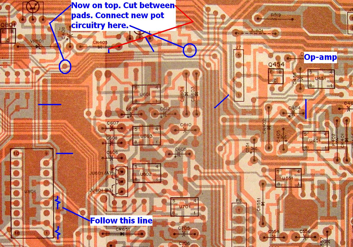
Here's a piece of the 9123A board's X-ray view showing the location of R810 and R811, which are underneath the board next to U801. The signal travels under the board to a feed-thru (circled on the image below). It then runs along the top of the board to another feed-thru (also circled). You can make your cut anywhere along this trace. Then connect the 27k resistor coming from the arm of the pot to this trace to the right of the cut, or at the rightmost feed-thru. The other signal points are obvious (ground and T9.6V). Click on the picture for a larger view.
Summary:
This modification was extremely successful and is highly recommended for any range MaxTrac that will be run out of its normal frequency range, especially one that refuses to control its output power when run out-of-band. The design and operation met all of my goals. The cost of the parts was under $3.00, and could probably be even less if you search through your junk box. I used 1/4-watt carbon-film resistors because that's what I had in the shack. The mod took me about 1/2 hour to perform, because I'm a stickler for details and actually tack-soldered the components into the circuit first by flying the components in the air, before putting them in their final position.
Acknowledgements and References:
Thanks go to Dave N1OFJ for providing and modifying the two MaxTracs to cover the 900 MHz frequencies. He's a whiz at making these things operate out-of-band.
The original power control modification that I started with was found at the Sierra Radio Association's web page, but that page and the k6sra.org web site have disappeared.
I also wish to thank the various people who reviewed this article and gave me several useful tips: John K1KSC, Scott KBØNLY, and Dave N1OFJ.
Scott KBØNLY suggested that I write a detailed article for the repeater-builder web site about doing this conversion. He was also helpful with the HTML conversion and getting this published.
Circuit information for the radios was obtained from Motorola's official service manuals.
Note from WA6ILQ:
This article was written to document a mod that prevents a runaway transmitter. The comments
in it could be taken to imply that you could have a high power 60w radio put out a stable
watt or two. They do not take into account the TX output spectrum. Most solid-state radios
get hot, dirty and squirrely when run below 1/2 power (with some models the rule of thumb is
2/3, some are 1/3). Basically, the efficiency of the transmitter drops at low power levels
due to impedance mismatches and it gets dirty when it gets hot, eventually burning itself
up. In other words, don't expect to be able to run your 60w radio at anything less than 30w
and stay clean, and the low point may be 40w or even 45w. If you are in the situation of
needing a lower powered transmitter, it's best to acquire another radio at no more than
twice the desired power level and set it where you want it. Above all, do a proper check
with a spectrum analyzer after you crank it down.
Contact Information:
The author can be contacted at: his-callsign [ at ] comcast [ dot ] net.
Back to the top of the page
Maxtrac Index
Motorola index
Back to Home
Article text, layout and hand-coded HTML © Copyright 2005 and date of last update by Robert W. Meister WA1MIK.
This web page, this web site, the information presented in and on its pages and in these modifications and conversions is © Copyrighted 1995 and (date of last update) by Kevin Custer W3KKC and multiple originating authors. All Rights Reserved, including that of paper and web publication elsewhere.