Back to Home
for the Motorola
MaraTrac Mobile Radio
By Robert W. Meister WA1MIK

|
MaraTrac index Back to Home |
Low Power Control for the Motorola MaraTrac Mobile Radio By Robert W. Meister WA1MIK |
|
Someone asked me what it would take to make a MaraTrac have a high/low power mode, such that when the site was running on battery the radio could transmit at a much lower power level. My curiosity got the better of me so I decided to experiment.
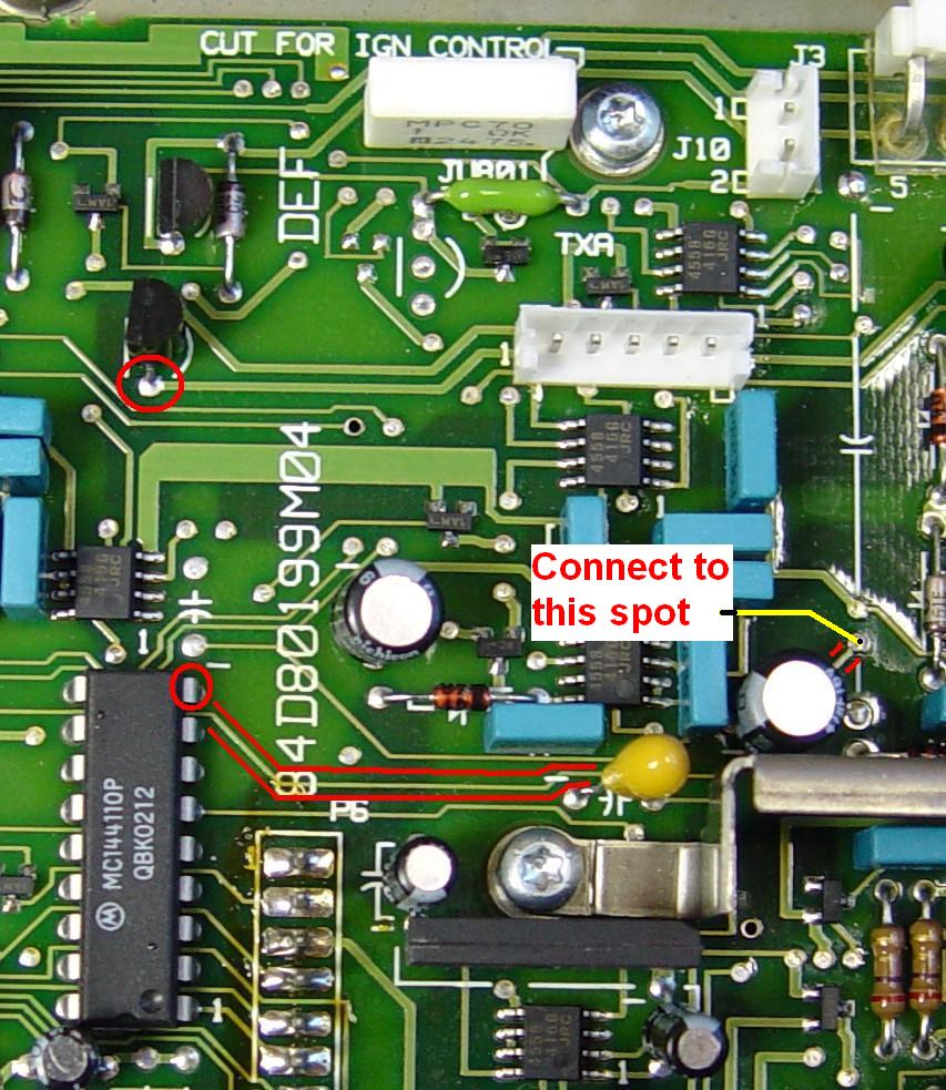
I used a MaraTrac previously programmed with 6-meter frequencies and chose 52.525 MHz as the test frequency. I adjusted the output power to 110 watts into a Bird 150w wattmeter terminated with a 50-ohm load. I used a radio that had previously been the test subject for manual power control; as such, it already had some modifications done to it that had been reversed. I wanted something simple that could be activated with just a simple ground connection. Refer to my MaraTrac Manual RF Power Control article here for further details. In the meantime, the photo below from the above article shows the spot where one end of the resistor goes; the other end goes to ground.
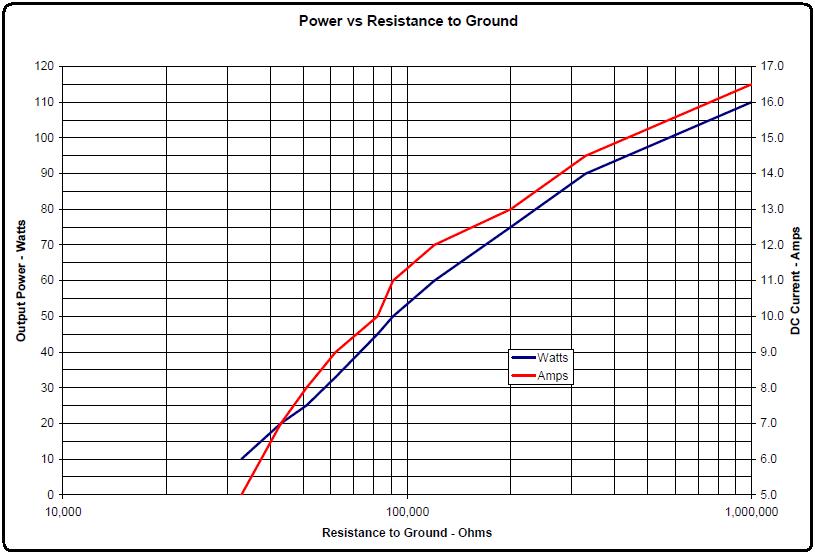
In the stock radio's logic board I just added resistance to ground from the point where the two 56k resistors join forces and would have been snipped out of the circuit. This has several advantages in that nothing else has to be done to the radio. No component changes, no cut foils, just one resistor and a means of grounding it. The resistor can be grounded with a dry relay contact, a simple transistor, or an open-collector IC output. Anything other than a dry relay contact will likely affect the resistance needed to reduce the output power. The initial power level set by RSS will also have an effect on the low power level. The table below shows the resistance value, output power, and DC current value as indicated on the Astron RS-35M power supply.
| Ohms | Watts | Amps | Notes |
|---|---|---|---|
| 33,000 | 10 | 5.0 | Do Not Use |
| 43,000 | 20 | 7.0 | Do Not Use |
| 51,000 | 25 | 8.0 | |
| 62,000 | 33 | 9.0 | |
| 82,000 | 45 | 10.0 | |
| 91,000 | 50 | 11.0 | |
| 120,000 | 60 | 12.0 | |
| 200,000 | 75 | 13.0 | |
| 330,000 | 90 | 14.5 | |
| 1,000,000 | 110 | 16.5 |
The two lowest resistance values caused strange behavior: the transmitter would initially jump to a high power level then suddenly go down to the value shown. For this reason, these lowest values are not recommended.
Here's a graph of the above table data.
The biggest problem with the MaraTrac is finding a way OUT of the inside of the radio. There are NO spare pins on the 19-pin control cable connector. The radio is very well sealed, top and bottom. You may have to drill a small hole somewhere and run a wire through it, or perhaps install a single-hole RCA jack and use the center contact wired to some external ground closure. I leave that "as an exercise for the student."
This same technique can be used on MaxTrac, Radius, and GM300 radios. Fortunately there ARE some unused pins on the MIC jack and Accessory connector to bring out such a signal.
Contact Information:
The author can be contacted at: his-callsign [ at ] comcast [ dot ] net.
Back to the top of the page
Up one level (MaraTrac index)
Back to Home
This article was conceived February 6, 2018.
Article text, artistic layout, and hand-coded HTML © Copyright 2018 by Robert W. Meister WA1MIK.
This web page, this web site, the information presented in and on its pages and in these modifications and conversions is © Copyrighted 1995 and (date of last update) by Kevin Custer W3KKC and multiple originating authors. All Rights Reserved, including that of paper and web publication elsewhere.