Up two levels
Back to Home
MaraTrac Squelch Circuit
By Robert W. Meister WA1MIK

|
Up one level Up two levels Back to Home |
Investigating the MaraTrac Squelch Circuit By Robert W. Meister WA1MIK |
|
The MaraTrac has an adaptive squelch circuit on its Audio/Squelch board. They do not use the squelch built into the RF board; that is used by the MaxTrac radio. Notes on the schematic diagram mention that the squelch closing time is short on strong signals (less than 10 milliseconds) and long on weak signals (up to 160 milliseconds).
How Squelch Circuits Work:
Detected audio comes in from the receiver. This signal is flat; no de-emphasis has been applied. In this case we want just the noise that resides in the frequency range of 5 kHz and above; any de-emphasis would have removed all of that. The audio is amplified and runs through the Squelch pot to adjust its level. High-pass filtering and additional amplification further clean up the noise. This noise signal is presented to a rectifier, which produces a DC voltage proportional to the amount of noise accompanying the signal. This DC voltage is compared to a fixed voltage at U1101A and if there's more noise voltage present, the squelch stays closed. As the signal strength increases and the noise level decreases, the noise voltage goes below the squelch threshold and the squelch opens.
The upper half of the schematic below is a standard squelch circuit with fixed opening and closing times. The lower half of the schematic adjusts the closing time based on the overall noise level of the signal. Click on the image below for a larger view. A much clearer view of the entire page extracted from the manual can be found here.
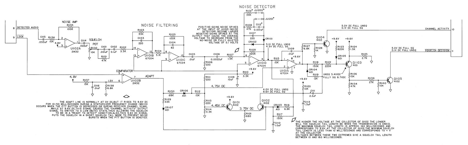
The ADAPT signal forces the squelch to close rapidly during scanning or when switching between receive and transmit. I will ignore this part of the circuit, as it has no effect on the receiver squelch timing that I'm testing.
Testing the Squelch Circuits:
All testing was performed on a stock MaraTrac low-band mobile radio on the 29-36 MHz split, tuned to 36 MHz. This radio did not have the remote squelch capability. It was the first radio I grabbed. I later repeated the tests with another low-band mobile radio on the 42-50 MHz split, modified and tuned to 52.525 MHz. This radio has the remote squelch capability.
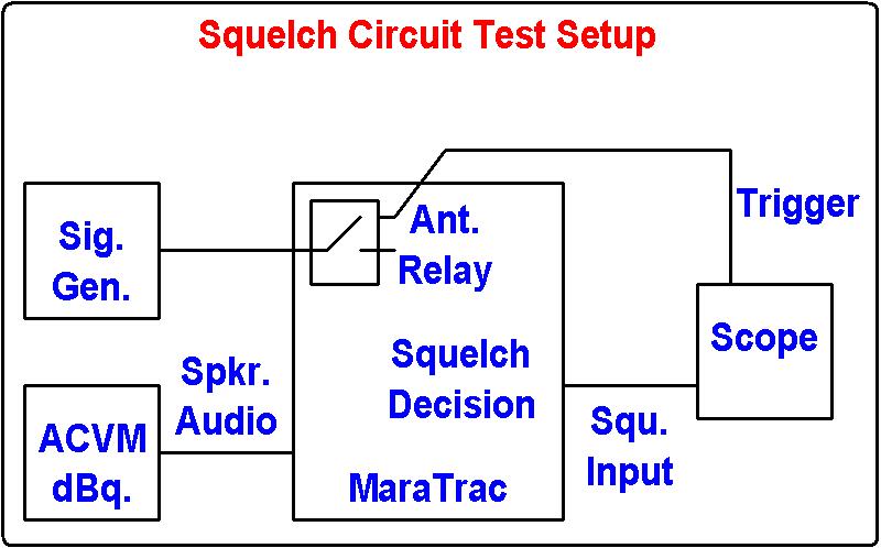
To test and measure the operation of the squelch circuits, I needed a way to turn the RF signal on and off and use that as the trigger to find out how long it took the squelch to open or close. None of my signal generators had a means of telling me when there was a signal present at the output or not, so I used the MaraTrac's antenna relay to do the switching.
I unplugged the antenna relay from the exciter board. I removed the bottom plate and soldered short wires to the points of interest.
I connected an RF signal generator to the antenna jack on the radio. This relay switches the antenna between the receiver and the transmitter. When energized, this relay disconnects the receiver input from the antenna and connects the transmitter output to the antenna. I connected one side of the coil to +9.6V in the radio at pin 7 of P21 on the A/S board; I just grounded the other side when I wanted to activate the relay. This ground also was used as a trigger signal to the oscilloscope. When the ground is connected and the relay is activated, no RF signal reaches the receiver and it squelches up. When the ground is released and the relay is de-activated, the RF signal passes through to the receiver and the squelch opens.
The AC voltmeter was connected to the loudspeaker output at the control head. I adjusted the volume for 0dBm on squelch noise with no signal. This is the reference level. When an input signal (without modulation) causes the meter to go to -20dBm, I know that the input signal is producing 20dB quieting in the receiver, and so forth. I actually determined the RF level required for several different levels of quieting first; then I reconnected the loudspeaker and measured the squelch timing using the RF levels previously determined.
The oscilloscope monitors the SQUELCH DECISION signal on the Audio/Squelch board at pin 11 of P21, the connector that goes to the interconnect board in the front of the radio. This signal is 5V (high) when the radio is squelched and 0V (low) when the radio is unsquelched. When the antenna relay is released (not grounded), the RF signal will be passed to the receiver, the scope will be triggered on the positive-going edge, and I can measure the squelch opening time as the time between the trigger and when the signal trace goes high. When the antenna relay is activated (grounded), no RF signal will be passed to the receiver, the scope will be triggered on the negative-going edge, and I can measure the squelch closing time as the time between the trigger and when the signal trace goes low. To repeat: when the relay is energized (its lead is grounded), the signal to the receiver is cut off and the squelch closes. The diagram below shows the test setup.
Test Results:
Rather than bore you with a lot of scope traces, I've tabulated the data instead. I measured the squelch opening and closing times for the receiver squelch at various levels of input signal quieting. The squelch pot was set to open at -130dBm, just a bit tighter than the squelch threshold, via the SQU pot on the A/S board. The input level is the signal strength in dBm that was required for the decibels of quieting being tested. All times are in milliseconds. I took five measurements for each condition and reported the fastest as Open to Closed and Closed to Open times.
| Input | dBq | O->C | C->O |
|---|---|---|---|
| -125.5 | 5 | 70 | 20 |
| -122.0 | 10 | 65 | 15 |
| -120.0 | 15 | 14 | 14 |
| -118.5 | 20 | 11 | 14 |
| -115.0 | 25 | 10 | 14 |
| -110.0 | 30 | 10 | 14 |
| -104.5 | 35 | 11 | 14 |
| -98.0 | 40 | 10 | 14 |
| -89.5 | 45 | 10 | 14 |
The receiver squelch open-to-close time is variable in the -122dBm to -118dBm input level range, representing 10-20dB quieting. The length of time increases as the signal gets weaker and the level of quieting gets lower. I stepped the input level in 1dB increments from -122 to -118dBm and the close times were 65, 25, 14, 14, and 11 milliseconds, respectively.
I was so surprised that the weak signal squelch closing time was so short that I repeated the tests on a second radio; I got similar results. The squelch opening time and fast closing time was 15 milliseconds and the longest squelch closing time was 80 milliseconds, even down into the noise around -128dBm. I didn't bother trying any other radios.
Conclusions:
The descriptions in the manual don't specify how fast the squelch opens, but my tests showed this to be a very consistent 14-15 milliseconds after carrier was applied. Analysis of the squelch circuit leads me to believe that the fast squelch closing time is equal to the squelch opening time. The squelch system seems to work about as described with a longer squelch tail taking effect between 15 and 20dB quieting. The fast closing time was 10-11 milliseconds and was very consistent. Surprisingly, on this radio, the long squelch closing time was far shorter than the advertised 160 milliseconds; in fact it didn't even reach half of that. The MaraTrac adaptive squelch system doesn't even come close to the performance of the famous MICOR M6709 squelch chip.
It's interesting to note that Motorola normally designs its systems so the squelch doesn't open until the signal strength produces 20dB quieting. Amateur radio operators usually adjust the squelch so it's right at the threshold.
Acknowledgements and Credits:
The squelch schematic came from the Motorola VHF Low-band MaraTrac Service manual.
Contact Information:
The author can be contacted at: his-callsign [ at ] comcast [ dot ] net.
Article text, photographs, and hand-coded HTML © Copyright 2015 By Robert W. Meister WA1MIK.
Up one level (MaraTrac index)
Up two levels (Moto index)
Back to Home
This article was created 27-May-2015
This web page, this web site, the information presented in and on its pages and in these modifications and conversions is © Copyrighted 1995 and (date of last update) by Kevin Custer W3KKC and multiple originating authors. All Rights Reserved, including that of paper and web publication elsewhere.