Motorola index
Back to Home
42-50 MHz MaxTrac
By Robert Meister WA1MIK
Maintained by Mike Morris WA6ILQ

|
Maxtrac Index Motorola index Back to Home |
99 Modes for a 42-50 MHz MaxTrac By Robert Meister WA1MIK Maintained by Mike Morris WA6ILQ |
|
Regular Motorola MaxTrac radios can have up to 32 modes (or channels) depending on the logic board, firmware, model number, and programmed features. Around 1990 Ontario (Canada) Hydroelectric power issued a Request For Quote (RFQ) for some small low-band radios with more than 32 modes. It must have been a large quantity as Motorola responded with a 99 mode special version of their 42-50 MHz MaxTrac to fulfill this need. Recently some of these "Ontario Hydro" low band Maxtracs have begun to show up on the surplus market.
To convert a standard MaxTrac to accept 99 modes, you need several important items:
The 99-mode firmware and software came on a CD in a plain brown package with no return address, just a typewritten note that said: "From the web, have fun". Don't even think of asking for it, and there's no way I'm going to make it available on any web or ftp site. If you find it somewhere, I'm not involved. The bigger EEPROM is a stock electronic component that can be purchased, along with a matching 28-pin IC socket, for under $4US.
Special Firmware:
The 99-mode firmware package is part number VLN5443A. (It did not show up on Motorola On-Line back in September 2008.) This PROM image is 32k bytes in size and will fit into a 27C256-20 EPROM. It has revision S5.37 embedded in it (I presume the "S" means "special"). For comparison, the regular MaxTrac full-featured, 32-mode firmware is revision 5.34. I already had a supply of EPROMs, but a new one would cost under $4US. Of course, you still need an EPROM programmer to write the image data to the chip.
Bigger EEPROM:
Some of the stock radio's code plug information is stored in a 24-pin, 28C16-12, which is a 2k byte parallel EEPROM. There is sufficient storage space in this device for the normal modes, but it's way too small for 99 modes, so a bigger EEPROM is necessary. The stock 2 kb EEPROM is soldered to the Maxtrac logic board. It must be removed to allow a 28C64 8K byte EEPROM to be installed, either directly soldered in or plugged into a socket. I purchased this part from Mouser, p/n 698-CAT28C64BLI-12 for $3.26US.
I opted to carefully remove the original 24-pin EEPROM, remove the solder from all 28 holes, install a 28-pin IC socket, and plug in a 28-pin, 28C64-12, which is an 8k byte parallel EEPROM that's equivalent to the original part. This probably has room for 128 modes, but as the MaxTrac control head can only display two digits, the limit is 99 modes. The socket was also purchased from Mouser, p/n 571-1-390262-2 for $0.32US.
Two soldered jumpers on the under-side of the logic board also need to be moved to deal with the bigger EEPROM and pin reassignments.
Specific Software:
The stock MaxTrac programming software didn't have sufficient storage space internally for a 99-mode code plug, so a special package was produced that did. It seems to be similar to the normal MaxTrac program, however there's only one low band entry in the MDF file, one that allows for 99 modes on the 42-50 MHz radio only. This special package goes by the product number RVN4020 or RVN4019 (depending on 3-1/2 or 5-1/4 inch floppy discs). As with all other MaxTrac packages, this only runs on a computer booted to pure DOS - no Windows or DOS Box. The program itself seems to restrict its use to just one particular model number (D51MJA9HA5_K) and seems to have been built on an older "lab" version (I found a menu item inside to blank a logic board, but I didn't find a way to access that menu item). I also found multiple references to 99 modes in the scan list. The special package had 1991 file dates.
Once running, it displays the following banner information (this is a transcribed representation of the actual screen text):
99 Channel MaxTrac Mobile
VERSION R05.20.01ACSP01
17-MAY-91
** CAUTION! This Software for use with 99 channel capable models only. **
Press Any Key To Continue
(C) Copyright MOTOROLA Inc. 1986 - 1990. All Rights Reserved.
Note the ACSP01 after the version number. Motorola often uses "AC" in the model number of some products to denote items made, or to be used, in Canada. "SP01" indicates a Special Purpose product.
I tried reading the code plug from an 800 MHz radio (that was the first one I grabbed). The program looked at the radio and displayed a strong warning message that the software will only deal with 99 channel radios, and if I try to proceed I risk corrupting the code plug. At least this proved the RIB and the communications path to the radio are working.
Programming Environment:
You will need an old, slow computer running MS-DOS to execute the programming software. It would NOT start up on my laptop computers equipped with an 850 MHz Pentium-III processor or even a 100 MHz Pentium-I processor, apparently it's from the era before the speed fix was made to the RSS. It ran just fine on a 25 MHz, 80486-based system running MS-DOS 3.3 and a color 40 MHz 80386-based system running MS-DOS 6.22. It probably requires a 25 to 40 MHz, 386 or 486-based computer to run properly, as these were the available models back in the early 1990s. Isn't modern technology wonderful?
I'm using an aftermarket RIB with a stock MaxTrac RJ-45 programming cable.
Radio Requirements:
Since the 99-mode version was only made for the 42-50 MHz radios, you need a working, 60 watt, multiple (more than two) channel radio with a 16-pin logic board. You should run through the Board Replacement procedure and write down any and all settings; that way you can just put them back into the radio if you don't have the required test equipment to align it fully. After replacing the EEPROM and firmware, the radio will have nothing valid or useful in its memory, so you will need to completely initialize the radio by re-entering those saved values when you go through the board initialization procedure. Doing a full alignment with test equipment takes longer, but it doesn't hurt to do this to the radio every once in a while anyway. There will also be no mode data in the radio, so you'll have to enter the various transmit and receive frequencies and coded squelch values from scratch as well.
Detailed Procedure:
You will have to almost fully disassemble the radio to do this. You'll need three Torx drivers: T15 for the control head, T10 for the plastic covers and board mounting screws, and T8 for the two flat-head screws that hold the logic board's heat sink to the chassis.
Remove the control head and plastic covers. Disconnect the control head and speaker from the logic board. Remove all the board shields. Unplug the two Taiko-Denki connector coax cables from the RF board. Remove the RF board (this makes it much easier to reinstall the logic board later). Unplug the PA power connector from the logic board. Remove the 16-pin accessory plug from the logic board. Finally remove the logic board, which is the only assembly you'll be working on. Clean the white heat-sink compound from the logic board's heat sink and the chassis. The following photo identifies the components you'll be working with on the original logic board:
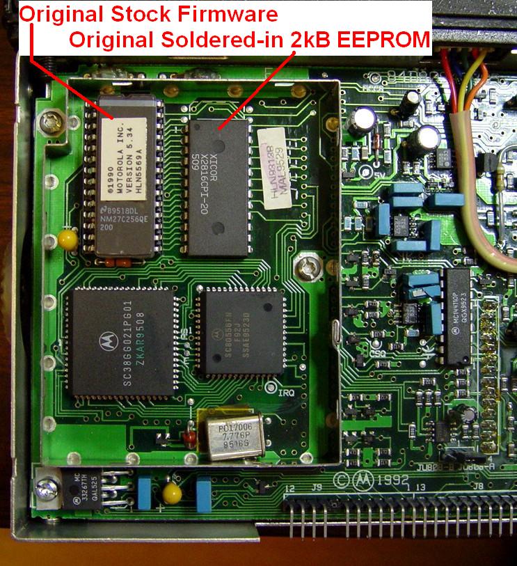
Starting in the upper left and moving clockwise, the labeled 28-pin socketed component is the NM27C256QE-200 firmware EPROM (U804), followed by the 24-pin X2816CPI-20 code plug EEPROM (U805), then the small square Motorola 6805 microprocessor, and finally the larger I/O expander chip. This article will deal with the two upper integrated circuits.
Remove (completely unsolder, or clip the pins and remove them separately) the parallel EEPROM (U805) from the logic board. Take the usual and customary static electricity precautions when working on this board. Remove the solder from the remaining four holes that were not occupied by the original EEPROM.
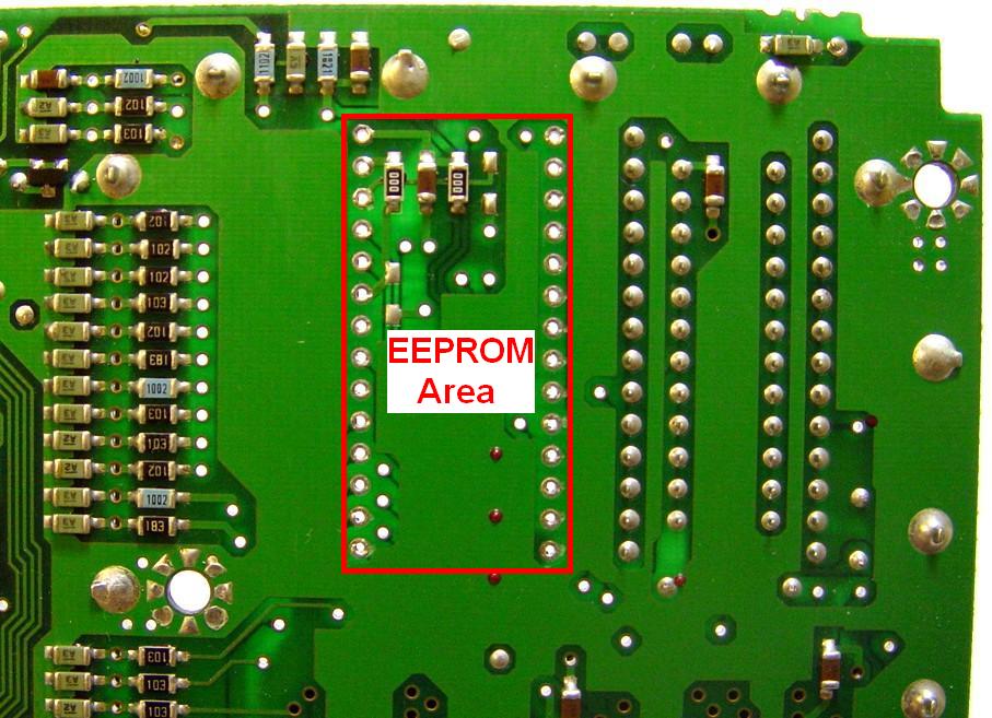
I usually use a 650F iron with a 1/16-inch tip and a vacuum-plunger style de-soldering tool. I've never had luck with Solder-Wick products; some people swear by them. As the solder melts, I push the IC pin towards the center of the hole with the iron then suck the solder out from the bottom. When done properly, the solder is removed from both sides of the circuit board. Afterwards I flip the board over and use a small screwdriver to slightly move the IC pins in the holes. This breaks the last little solder bond remaining. The IC usually falls out after that. Everyone has his/her own procedure; use what works for you. Below is a photo of the rear of the board prepared for the new socket. Note the three surface-mount components in the upper left corner of the highlighted area; we will be working with them shortly.
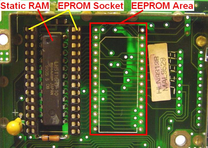
And here's the view from the front of the board. Note that the already socketed firmware EPROM (U804) has been removed. The smaller IC under the socket is the static RAM chip (U806) used by the microprocessor. Don't mess with that.
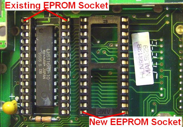
Clean both sides of the board (where you unsoldered the EEPROM) with flux remover or alcohol. Install the 28-pin socket into the board (you will install the new EEPROM later) or (if you're brave) solder the new EEPROM directly into the board. Make sure you install the socket and/or new EEPROM properly. Pin 1 is in the upper left corner of all the DIP ICs as viewed in these photos. The notch in the socket (if there is one) is on the Pin 1 end. In the photo below the notch is visible above the molded-in "28". Here's the socket installed:
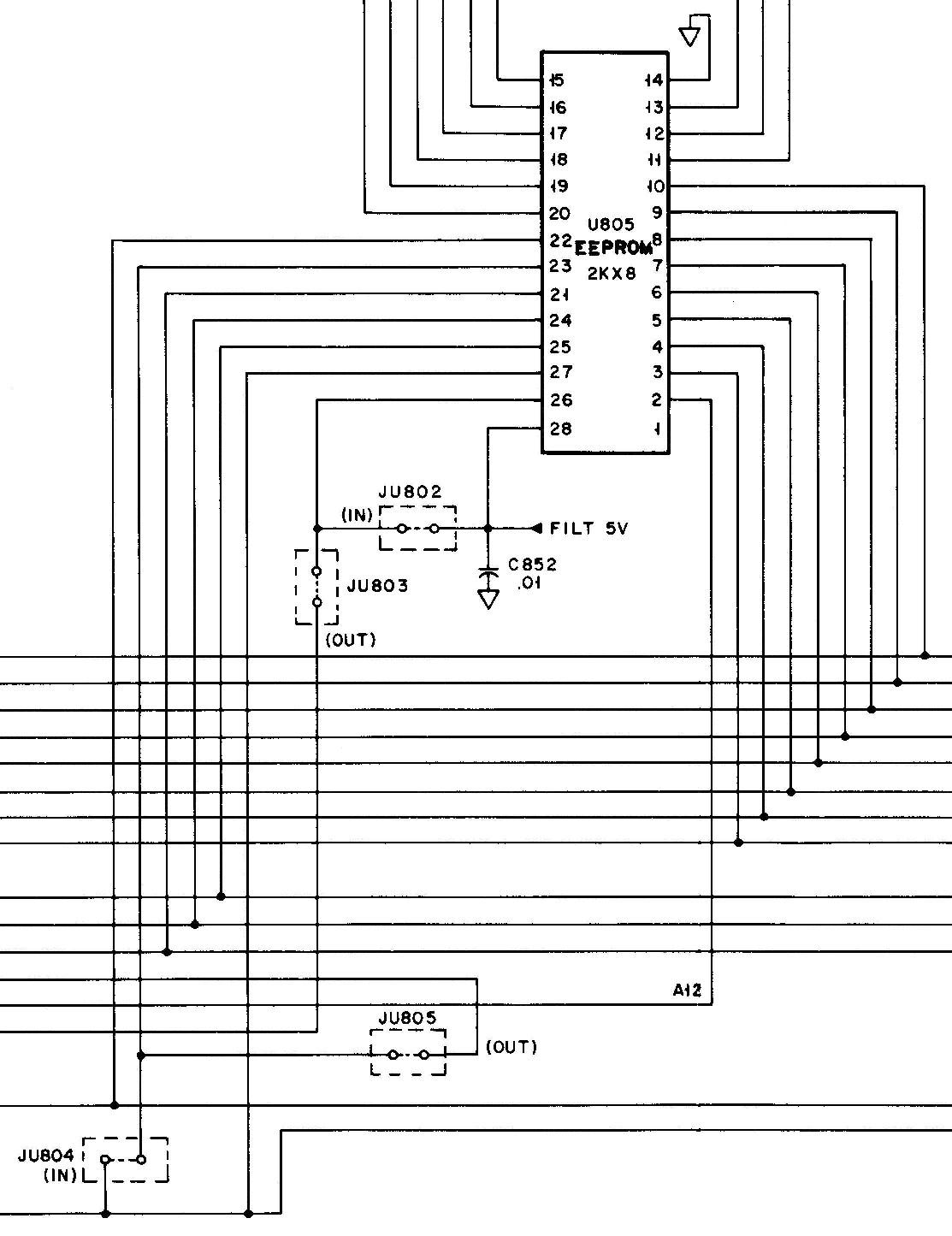
There are two pairs of jumpers on the solder side of the logic board, under the EEPROM, that need to be swapped or reversed. The normal configuration, for a 28C16 EEPROM, has JU802 and JU804 installed, and JU803 and JU805 removed. They need to be moved to deal with the additional pins on the bigger 28C64 EEPROM. The original schematic from the Service manual shows the stock configuration:
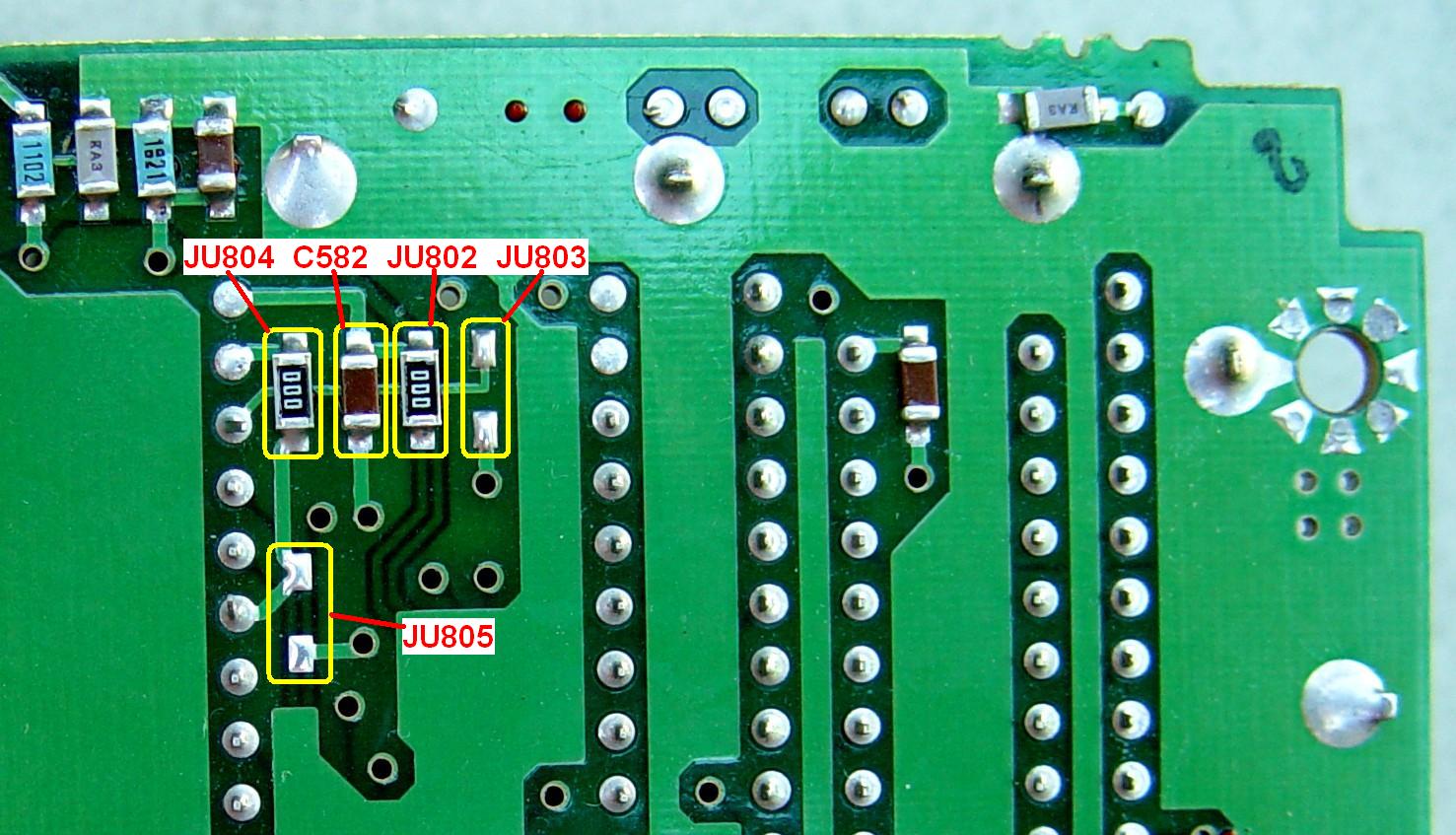
Remove the two installed jumpers JU802 and JU804, and put them into the spots reserved for JU803 and JU805. These are actually zero-ohm resistors and they're VERY small. Normally they're glued to the board but mine were rather loose, and I lost one. (I found it later when cleaning up.) You may find it easier to just remove JU802 and JU804 and install short bare wire jumpers, rather than reinstall the removed parts, where JU803 and JU805 would go, as I did. You must only have one pair of jumpers installed when you're finished: JU802/JU804 or JU803/JU805. The photo below shows the locations of these jumpers on the logic board before being changed:
Here's that same area of the board with the socket installed and the jumpers in their new location (JU803/JU805):

If you previously installed an IC socket, you can now plug the new 28C64 EEPROM into it. Make sure you properly orient it (pin 1 is marked on the logic board and is the furthest away from the microprocessor), it's fully seated, and no pins are bent over. The markings on the EEPROM were only visible when the IC was held at a critical angle to the light source. It IS stamped with the 28C64 part number; it just would not show up in any of my photographs.
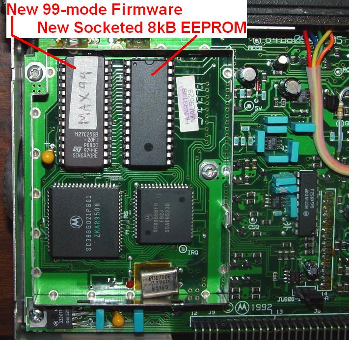
Remove the original firmware EPROM at U804 and replace it with the new VLN5443A firmware EPROM. I used a USB-powered EPROM burner, model GQ-4X, which I purchased from MCUmall, and a recycled 27C256-20. I could have erased the existing firmware and reused the EPROM that was originally in the radio. Here's the completed logic board. Other than the EPROM label, it looks just like it might have come from Motorola:
Finally, add some clean heat-sink compound to the logic board's heat-sink, reinstall the logic board and its shield, the PA power connector, the RF board (leave the shields off for now as you'll need the crystal data for initialization), the two Taiko-Denki coax cables, all mounting screws, and finally plug the control head cables into the radio. This concludes the hardware modifications.
Software Initialization:
The radio will be rather confused at this point. You've just installed a new brain and taken away much of its worldly knowledge. The radio is now looking to you for guidance and input. Treat it just like any other MaxTrac that's about to get a new model number; you will need MaxTrac lab software to blank it. It doesn't matter if you use a normal or extended code plug, clearing or retaining tuning values. I use normal/clear because it's faster.
Surprisingly, I found that the radio still knew it had its original 19 modes and was quite happy. I suspect that the EEPROM in the microprocessor was sufficient to hold some of the code plug information, but I went ahead and started fresh anyway.
Connect the radio to an adequate source of power and a dummy load. Start the 99-mode software and go to the Service Menu, Board Replacement, Logic Board. You'll be presented with a screen preset for a Max High Sig, MaxTrac 300, 42.0-50.0 MHz, model number D51MJA9HA5_K (this is the only 99-mode low-band model number in the MDF file), and panel number 001. All you have to do is enter the original serial number and press F8. The new code plug will be written out to the radio, all 1088 blocks of it (a 32-mode radio only has 320 blocks). This takes about two minutes, so be patient. Go back into the same Logic Board Replacement menu and perform the rest of the procedure to enter the crystal and tuning data, the 9.6V reading, and all the other alignment parameters. Several good articles on this very web site cover these steps in greater detail. There's also an article that tells you how to convert the radio so it covers 46-54 MHz; this would be a good time to do it.
The radio will emit a rather long "boooooop" every time it resets, which happens almost every time you read or write the code plug. This is an error indication that means the code plug is incomplete or empty, and since the radio has just been initialized, it is quite lonely. It will do this until you enter at least one mode and write the code plug back to the radio. The regular MaxTrac software solves this by configuring one mode during board initialization. You won't be able to enter amateur frequencies into the mode screen until you hex-edit the software; see the procedure below. For now, any receive frequency between 42 and 50 MHz will make the radio happy.
Final Steps:
When you've finished initializing the radio, reinstall the VCO and RF board shields and put the covers back on the radio. The only thing left to do is program the 99 modes as you see fit. Remember, as this is still a MaxTrac, it may have problems maintaining its output power and deviation outside the 42-50 MHz range. There are other articles on this web site that deal with these problems too.
You'll have to hex-edit the MDF file to allow frequencies higher than 50 MHz to be entered. The SHIFT-NUM trick doesn't work with this old program. See the procedure later in this article.
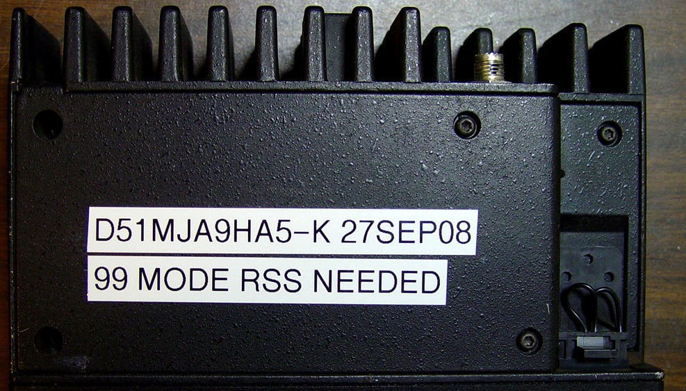
It would be useful to add a note near the model number sticker that mentions the new model number and that the radio is now capable of 99 modes and can't be programmed with the stock MaxTrac software. You or the next owner will thank you for the effort. Nothing fancy. Here's what I added to the PA cover under the radio:
Restoring the Radio:
If you ever want to return this radio back to its original configuration, you should only have to plug in the original firmware EPROM and blank and initialize the radio with the appropriate MaxTrac software packages. The bigger EEPROM should work just fine with only 32 modes.
If you installed the 28-pin IC socket, you could also put the original under-board jumpers back and plug in the original 28C16 EEPROM, IN THE PROPER LOCATION (ignoring the two upper pins in each row of the socket), and you would have the original code plug and alignment data to work with.
One software issue has surfaced. If you read the radio and save the code plug to disk, you may not be able to read the saved code plug and write it to the radio. This happened to me and at least one other person. I had to read the code plug fresh from the radio, modify it, and write it back to the radio. However, if you start RSS, read the code plug from the radio, then read the saved code plug from disk, you can then write the saved code plug to the radio. You only have a problem if you start RSS, read a code plug from disk, and try to write that to the radio.
Reference Data:
The data sheet for the original 2k byte 28C16 EEPROM is found in this document.
The data sheet for the new 16k byte 28C64 EEPROM is found in this document.
Hex-Editing the MDF file:
The MAXTRAC.MDF file restricts frequency programming to 42.0-50.0 MHz on the 99-mode low-band radio. The 99-mode software does not allow you to use the SHIFT-NUM trick to exceed that range; apparently that was a feature that came into existence much later. You have to hex-edit the frequency range table in the MDF file to allow entry of amateur frequencies. I use Hex Workshop from www.bpsoft.com.
The following table describes the 42.0-50.0 MHz entry and indicates which values need to be changed to expand the range to 42.0-54.0 MHz. All values are shown as 16-bit (two-byte) data. There is a file checksum that must be corrected after you change the values. With Hex Workshop, choose "Tools" from the top-line menu, then "Generate Checksum"; select "Checksum (16-bit)" and "On Entire File" then click "Generate". The original 16-bit checksum value is 3EBD; make sure it is still 3EBD after you finish applying these changes. I modified locations used by an 800 MHz MaxTrac model entry to fix the checksum; I felt that changing them wouldn't have any noticeable affect on the program, which only seems to work on the 42-50 MHz low-band radio. These are shown at the end of the table.
You only have to enter the five values in the right-most "New Data - Hex" column, at their respective addresses shown in the left-most "Hex Addr." column. Verify that the original hex value matches what's shown below before you change it to the new value.
| Hex Addr. |
Original Data | Real Value |
New Data | |||
|---|---|---|---|---|---|---|
| Hex | Flipped | Dec. | Dec. | Hex | ||
| 03B6 | A401 | 01A4 | 420 | 42.0 | - - - | - - - |
| 03B8 | F401 | 01F4 | 500 | 50.0 | 540 | 1C02 |
| 03BA | A401 | 01A4 | 420 | 42.0 | - - - | - - - |
| 03BC | F401 | 01F4 | 500 | 50.0 | 540 | 1C02 |
| 03BE | A401 | 01A4 | 420 | 42.0 | - - - | - - - |
| 03C0 | F401 | 01F4 | 500 | 50.0 | 540 | 1C02 |
| 03C2 | A401 | 01A4 | 420 | 42.0 | - - - | - - - |
| 03C4 | 1C02 | 021C | 540 | 54.0 | - - - | - - - |
| 2506 | 4D57 | - - - | - - - | - - - | - - - | F0F0 |
| 2508 | 4135 | - - - | - - - | - - - | - - - | E0DF |
The MDF file, as modified above, was tested with the software. It allowed me to easily enter 52.5250 for both transmit and receive frequencies. I could also read, save and write the code plug. I verified that the radio did, in fact, accept the new code plug and transmitted on the amateur frequencies, just like it did originally. Before I started the modification, I went through the alignment steps and wrote down every setting. During initialization of the radio I just restored those exact same values. This insured that the radio would perform the same after the modification.
Some New and Unique Features:
Besides the obvious increase in available channels, the 99 channel RSS gives you a few things regular RSS doesn't. The following text was taken directly from the HELP file that comes with the package; spelling errors have been corrected but it's still confusing to me. TalkAround is enabled on the Radio Wide screen.
TALKAROUND (99 Channel Version Only)
When TalkAround is enabled, the number of programmed frequencies will be divided in half with each half being placed into an upper and a lower bank of frequencies. Only one frequency bank at a time is available to the operator. To switch between the upper and lower frequency banks, press and hold down the Monitor Button until you hear three beeps. Repeat this procedure to change banks a second or third time. (When in TalkAround mode, the display will alternately flash the mode number or the letter "d".) To ensure correct TalkAround operation the frequencies in the upper bank must be programmed as simplex channels. For example, if 80 modes are programmed into the radio, modes 1 to 40 will become the lower frequency bank and modes 41 to 80 will be the upper bank of frequencies. Only half of the total number of programmed modes will be accessible using the mode select buttons on the front panel. Switching to either the upper or lower bank will give you access to the second half of your frequencies.
CHANNEL SCAN LIST (99 Channel Version)
MAXTRAC models with Mode-Slaved Channel Scan may have a unique Scan List for each conventional mode with up to 32 modes in each Scan List including a First and Second Priority mode. The First Priority will always match the selected mode and cannot be changed (for example, if mode 4 is the selected mode then mode 4 is the First Priority). The Second Priority is set from the Radio Wide screen and is the same in all Scan Lists (for example, if mode 6 is chosen as the Second Priority in the Radio Wide menu then mode 6 will become the Second Priority in all Scan Lists).
Any other mode between 1 and 99 can be selected as a Non-Priority channel. The Scan List screen consists of 4 screens known as Pages. The 4 Pages are required to display all 99 entry fields. Use the Page Up and Page Down buttons to scroll through the Pages.
MODE SLAVED SCAN LIST (99 Channel Version)
This screen displays the available modes and their scan TYPE for the mode display in the upper left side of the display. The scan types are changed by moving the cursor with the Enter or Tab keys to the desired Mode and changing its TYPE by using the up and down arrow keys. The PageUp and PageDown keys allow you to scroll through the four pages that make up the 99 channel list. Note that Priority One is always the Mode that the current scan list is slaved to. This priority cannot be changed.
Musings...
Since the 99 channel hardware changes are only made to the logic board it should be possible to create a 99 channel 10 meter, VHF or UHF Maxtrac. All it should take is creating the appropriate entries in the MDF file (perhaps overwriting some of the unused 800 MHz. entries). I've not done any research or experimentation on this. If anybody does, Repeater-Builder would be happy to host a similar article, update this paragraph, or both. And you can donate the information anonymously if you wish.
Contact Information:
The author can be contacted at: his-callsign [ at ] comcast [ dot ] net.
DO NOT ask for copies of any of the special items discussed in this article; they are
not available from me.
Any e-mails that inquire about obtaining the firmware or software will be ignored.
Back to the top of the page
Up one level (Maxtrac Index)
Up two levels (Motorola index)
Back to Home
This page originally posted on Sunday 28-Sep-2008.
Photographs, article text, and hand-coded HTML © Copyright 2008 by Robert W. Meister WA1MIK.
This web page, this web site, the information presented in and on its pages and in these modifications and conversions is © Copyrighted 1995 and (date of last update) by Kevin Custer W3KKC and multiple originating authors. All Rights Reserved, including that of paper and web publication elsewhere.