Motorola index
Home page
GM300 Mobile Radio
By Robert W. Meister WA1MIK

|
Maxtrac Index Motorola index Home page |
Disassembling the Motorola GM300 Mobile Radio By Robert W. Meister WA1MIK |
|
Background:
So your GM300 is giving you troubles, such as being several kHz or more off frequency. This is a known problem on these radios. It is caused by dirty interconnection pins between the logic board and the RF board, primarily the pin that controls the frequency of the reference oscillator in the synthesizer. All you have to do is clean the pins on that interconnect assembly. Easier said than done. To do it, you have to take the radio completely apart.
You'll need three tools to do the job successfully:
Photos will precede and accompany the descriptive text and all screws will be indicated with yellow circles. Follow each step, taking care to read the important notes, if any. You can reassemble the radio by following the steps in the reverse order. When you're finished, connect the radio to a dummy load, frequency counter, and a computer running GM300 RSS, go to the SERVICE menu (F2), ALIGNMENT: Transmitter and Receiver (F2), then REFERENCE OSCILLATOR WARP Adjustment (F5) and adjust the frequency. Typical values are 99-103. If you have to go further, there's still a problem with the radio.
You can use a similar procedure to disassemble a MaxTrac or Radius mobile radio, however the interconnect pins are not a separate assembly; they're soldered to the logic board and come out with it. Also you'll need a Torx T8 driver to remove two small flathead screws from the side of the radio that holds the logic board's heat sink to the chassis. You'll also need some paper towels to clean the old heat sink compound off the chassis and the heat sink after you remove it, and some new heat sink compound will need to be used when you reassemble the radio.
Taking It Apart:
Click on any photo for a larger view. Here we go.
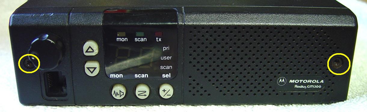
Using the T15 driver, remove the two T15 cap screws on each end of the front control panel.
Disconnect the two cable connectors by prying them towards the front of the radio.
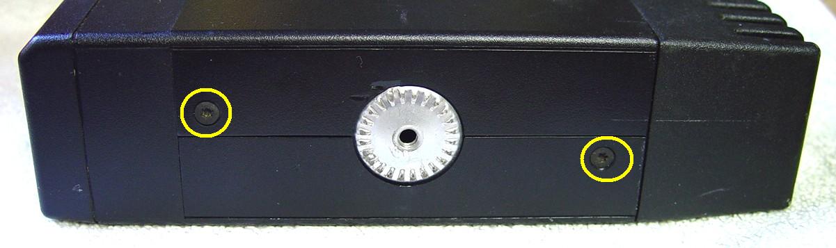
Use the T10 driver for all the rest of the steps. Remove two T10 flathead screws on each side of the radio. Remove the plastic top and bottom covers; they just pry off but pry both sides up equally as they interlock and might break if you force one side up more than 1/4 inch. Remove the full-size shields on the top and bottom of the radio by prying them off starting at the corners. Note that an arrow points to the front. These shields are identical so it doesn't matter which one goes back on the top or the bottom.
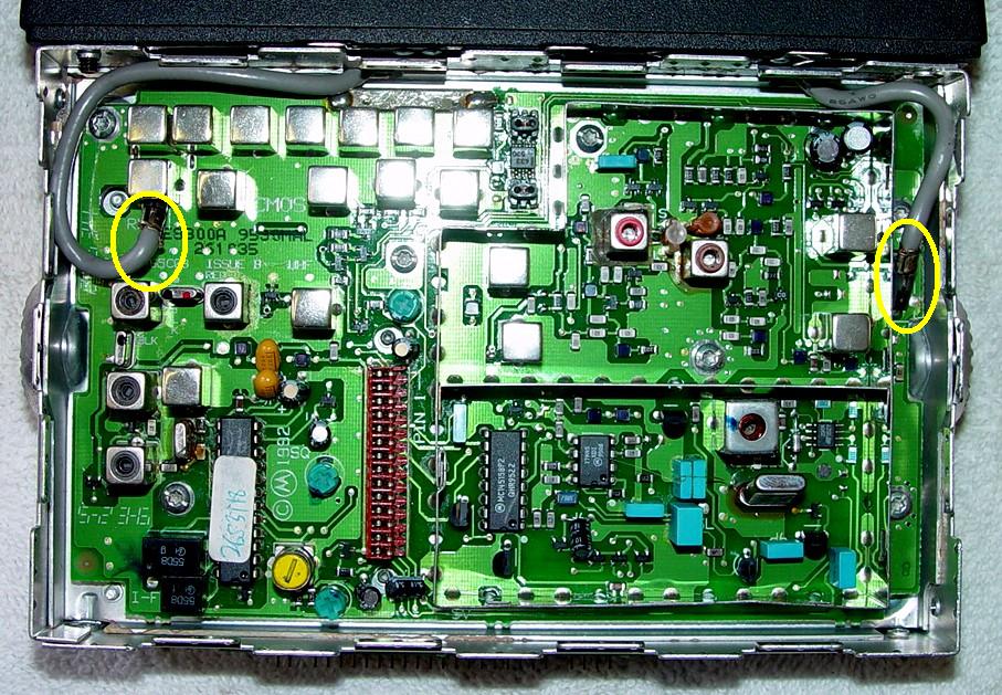
Remove the shield over the synthesizer section of the RF board by prying it up and off. Unplug the two coaxial cables on the left and right sides of the RF board. They just unplug with a slight twisting motion.
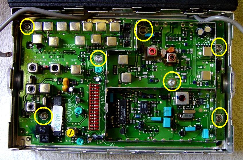
Remove the seven T10 screws on the RF board. Gently pry the RF board up off the chassis starting at the front. The interconnect pins will resist your pulling action but the board will come off if all the screws have been removed. There's really no need to remove the RF board, but it makes the rest of the procedure a bit easier.
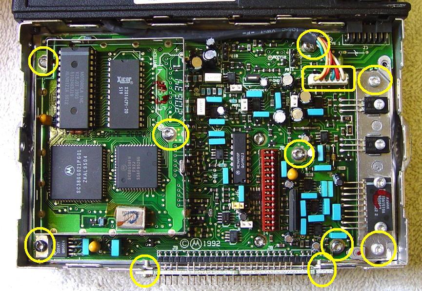
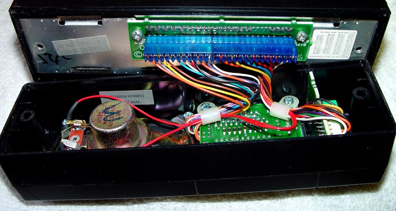
Flip the radio over and remove the shield over the microprocessor section of the logic board by prying it up and off. This photo shows an enhanced four-layer logic board. The masked two-layer logic board doesn't have a shield over the microprocessor section but everything else will be in similar locations. Unplug the 6-wire cable going to the Power Amplifier at the rear of the radio. It just pulls straight up. Unplug any accessory connector from the rear of the radio. Remove the two T10 screws that hold the front connector strip to the chassis. Remove the six T10 screws on the logic board. Remove the two T10 screws on the heat sink at the right. Note that these two screws are longer than any of the other T10 screws. Gently pry the logic board up off the chassis starting at the front. The interconnect pins will resist your pulling action but the board will come off if all the screws have been removed.
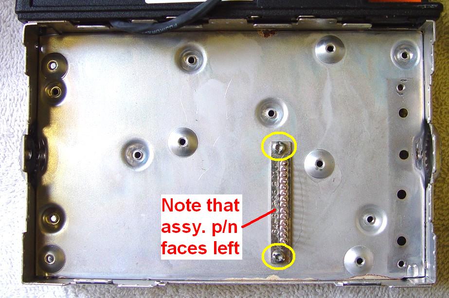
Finally remove the two T10 screws holding the interconnect pin assembly. This is what we came here to get. Note there is a part number on the metal strip; this faces the left side of the radio and faces up when you put it back in from the bottom (logic board side) of the chassis.
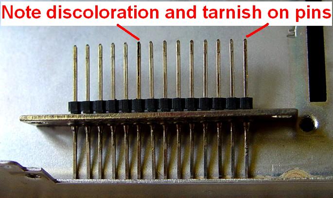
Using some fine steel wool, scrub the left and right surfaces of the 14 interconnect pins. Make sure they're all nice and bright or at least have the same amount of shine. Wipe the pins off and make sure there are no loose pieces of steel wool remaining on the assembly.
If you have a 1/16 inch twist drill bit, push that through each of the 14 holes in the mating connector on both the RF board and the logic board. Don't twist the drill bit, just push it through so it scrapes any corrosion off the contacts. If you don't have a drill bit of the appropriate size, push the interconnect pin assembly into the mating connector of each board and remove it several times to scrape the contacts. If you have some good contact cleaner, apply a light coating to the pins by spraying some on a piece of cloth or paper towel and wiping the pins with it.
Reassemble the radio in the reverse order starting with the interconnect pin assembly, making sure to orient it properly. The plastic insulator fits into the slot in the chassis. Install it from the logic board (under) side of the chassis but don't tighten its mounting screws fully; leave it loose. You can access them through holes in the logic board later. Install and reconnect the logic board. Install and reconnect the RF board. Once the two boards are secured, you can tighten the interconnect pin assembly's mounting screws through the access holes in the logic board. Install the shields. Install the top and bottom plastic covers. Plug the control head connectors onto the front of the logic board and install the control head. Now test and adjust the radio's warp frequency if necessary.
A Real Success Story:
I acquired a clean 40w UHF 16 channel GM300 radio from a well-known auction site. I put it on the bench, read the code plug, and found that channel 1 was programmed to transmit on 469.750000 MHz. I plugged a microphone in and pressed the PTT button. The output power was 35 watts and the counter showed 469.747777 MHz, so the radio was 2.223 kHz low. Since the Reference Oscillator Warp adjustment was set to 102, I knew the radio was already suffering from dirty interconnect pins and would only get worse.
After taking the radio apart, cleaning the pins, squirting them with some silicone-based contact cleaner, inserting the interconnect pin assembly into both the RF board and the logic board several times, I reassembled the radio and measured it again. The transmit frequency was now 469.749726 MHz, only 274 Hz low, and the output power was exactly 40 watts. Not bad for half an hour's work, which included taking photos for this article.
Contact Information:
The author can be contacted at: his-callsign [ at ] comcast [ dot ] net.
Back to the top of the page
Maxtrac Index
Motorola Index
Back to Home
This article created 27-Oct-2015.
This web page, this web site, the information presented in and on its pages and in these modifications and conversions is © Copyrighted 1995 and (date of last update) by Kevin Custer W3KKC and multiple originating authors. All Rights Reserved, including that of paper and web publication elsewhere.