Motorola index
Home page
Motorola GM300
Narrow-Band
Conversion Kits
25 kHz to 12.5 kHz Channel Spacing Conversion Kits for GM300, M10, M120, and M130 Series Mobile Radios
Kit Numbers HLN9575 and HLN9576
Transcribed by Robert W. Meister WA1MIK

|
Maxtrac Index Motorola index Home page |
Motorola GM300 Narrow-Band Conversion Kits 25 kHz to 12.5 kHz Channel Spacing Conversion Kits for GM300, M10, M120, and M130 Series Mobile Radios Kit Numbers HLN9575 and HLN9576 Transcribed by Robert W. Meister WA1MIK |
|
PLEASE NOTE: This instruction sheet is provided as a guide for technically competent service personnel who are familiar with electronic communications circuitry and test equipment. If you are not confident in your ability to understand and complete the instructions, or you lack the proper test equipment: STOP -- Do not continue.
NOTE: These conversion kits can also be used on limited versions of the Radius M100, M200, and MaxTrac mobile radios. The VHF RF boards must be HLD4321C (or later) or HLD4322C (or later). The UHF RF boards must be HLE9310B (or later). Refer to the specific radio service manual to find the circuit details and PC board overlays for each model. It might even be possible to apply similar parts changes to an 800 MHz MaxTrac RF board (HLF9122) for narrow-band use on the 900 MHz amateur band.
ALSO NOTE: The GM300 radio, after conversion, will only be capable of receiving narrow-band signals properly. The transmitter deviation can be set for 2.5 kHz or 5.0 kHz. Regardless, the GM300 radios do not support the ability to select narrow-band or wide-band operation on a channel-by-channel basis. You'd need a CDM-series radio to have that ability.
Lastly, the included documentation says they are from June 1995, so this field conversion has been around since the radio models were new, this is not something that is a reaction to the recent narrowbanding mandate.
Description:
The HLN9575 Conversion Kit for the VHF models and the HLN9576 Conversion Kit for the UHF models are used to convert the GM300, M10, M120, and M130 series of Radius mobile radios from 25 kHz to 12.5 kHz channel spacing. These kits WERE available from MyRadioMall for about $65 each in October 2011. The Motorola On-Line retail price is about $85, but when I tried to order one, the system said they were Not Available yet they anticipated shipment in 2-3 days. I checked the availability again in June 2012 and Motorola has changed their status to "obsolete, no replacement available." I even called Parts ID and they have nothing to offer as a substitute, so it seems they don't have any of these kits left. They want you to buy a newer radio (from them, of course) and there probably are plenty to choose from.
Equipment Needed:
Conversion Kit HLN9575 for VHF Models (136-174 MHz):
Table 1 lists the reference (from the schematic diagram and parts list in the service manual), the part number (value) to remove from the 25 kHz board, and the part number (value) to replace it with, to convert the board to 12.5 kHz.
| Component Reference | Part Number (Value) on 25 kHz Board TO BE REMOVED |
Part Number (Value) for 12.5 kHz Board TO BE REPLACED WITH |
|---|---|---|
| FL51 | 9180097D06 (455 kHz 6D) | 9180097D04 (455 kHz 6F) |
| FL52 | 9180098D06 (455 kHz 4D) | 9180098D04 (455 kHz 4F) |
| R61 | 0611077B19 (68k) | 0611077B07 (22k) |
| R62 | 0611077B09 (27k) | 0611077A26 (10) |
| R163 | 0611077A50 (100) | 0611077B11 (33k) |
| R165 | 0611077B03 (15k) | 0611077A98 (10k) |
| R223 | 0611077A66 (470) | 0611077A92 (3.6k) |
| R225 | 0611077B01 (12k) | 0611077A92 (5.6k) |
| Y51 (a&b) | 9180022M02 (45.1 MHz, 25 kHz) | 9180022M03 (45.1 MHz, 12.5 kHz) |
Conversion Kit HLN9576 for UHF Models (403-512 MHz):
Table 2 lists the reference (from the schematic diagram and parts list in the service manual), the part number (value) to remove from the 25 kHz board, and the part number (value) to replace it with, to convert the board to 12.5 kHz.
| Component Reference | Part Number (Value) on 25 kHz Board TO BE REMOVED |
Part Number (Value) for 12.5 kHz Board TO BE REPLACED WITH |
|---|---|---|
| FL51 | 9180097D06 (455 kHz 6D) | 9180097D04 (455 kHz 6F) |
| FL52 | 9180098D06 (455 kHz 4D) | 9180098D04 (455 kHz 4F) |
| R61 | 0611077B19 (68k) | 0611077B07 (22k) |
| R62 | 0611077B09 (27k) | 0611077A26 (10) |
| R163 | 0611077A50 (100k) | 0611077B11 (33k) |
| R165 | 0611077B03 (15k) | 0611077A98 (10k) |
| R301 | 0611077A82 (2.2k) | 0611077B03 (15k) |
| Y51 (a&b) | 9180022M02 (45.1 MHz, 25 kHz) | 9180022M03 (45.1 MHz, 12.5 kHz) |
Converting Your 25 kHz Radio to a 12.5 kHz Radio:
Replacing the Board Components:
Carefully remove and replace receiver components FL51, FL52, R61, R62, and Y51 (a&b) listed in Table 1 or Table 2, depending on the radio's model.
Receiver Alignment:
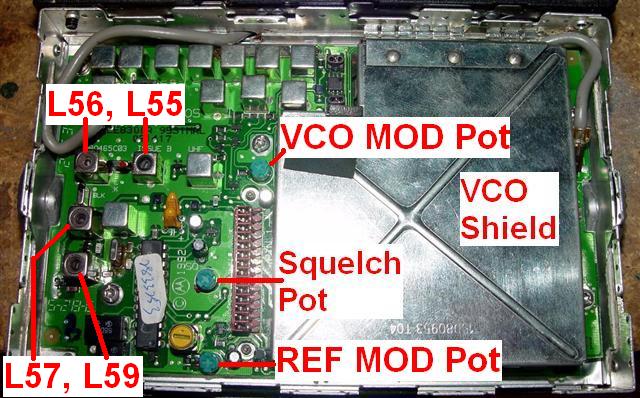
Use a Communications System Analyzer, operating in the "Generate" mode, connected to the radio's antenna jack. The photo below of a UHF RF board identifies the pots and coils that need to be adjusted; the VHF RF board is similar. The "I-F" test point is pin 24 (lower left pin, closest to FL52) of the receiver IF chip (the 24-pin IC with the tuning data sticker on it); this doesn't appear to be marked on the circuit board.
Receiver 45.1 MHz IF Alignment:
Squelch Sensitivity Adjustment:
Transmitter Alignment:
Replacement of the transmitter circuitry chip resistors shown in Table 1 (R163, R165, R223, and R225) for VHF models, or Table 2 (R163, R165, and R301) for UHF models, may not be necessary. Use the following procedure to determine if further modifications are required. For the transmitter measurements, use the Communications System Analyzer operating in the "Monitor" mode.
VCO Modulation Adjustment:
Reference Oscillator Deviation:
Acknowledgements and Credits:
The information contained in this article came from the official kit instruction document: 6880904Z18-O, dated June 1995, as well as perusal of the GM300 Service Manual 6880902Z32, both of which are available as PDF files on this web site. Additional comments have been added and the format has been changed. I have also corrected several errors that were present in the original document.
Disclaimer:
The person who transcribed this information has NOT performed the conversion himself. He's just the messenger. Don't blame him for any errors or discrepancies.
Contact Information:
The author can be contacted at: his-callsign [ at ] comcast [ dot ] net.
Back to the top of the page
Maxtrac Index
Motorola Index
Back to Home
This article first posted 29-Nov-2010.
This web page, this web site, the information presented in and on its pages and in these modifications and conversions is © Copyrighted 1995 and (date of last update) by Kevin Custer W3KKC and multiple originating authors. All Rights Reserved, including that of paper and web publication elsewhere.