Motorola index
Back to Home
By Robert W. Meister WA1MIK

|
MaxTrac index Motorola index Back to Home |
MaxTrac Adjustments By Robert W. Meister WA1MIK |
|
This article deals with the various coils and potentiometers on the MaxTrac (and some Radius, GM300, and MaraTrac) RF Boards. It describes their function and suggests adjustment procedures. I'm sure Motorola aligns these boards on a test jig, but as we only have entire radios at our disposal, this will have to do.
Adjustable Components:
The following table summarizes the adjustable coils and potentiometers that are involved with frequency, deviation, and squelch. All of these are on the RF board. The location of these components varies somewhat. The photos below are representative of the various adjustments.
All of the pots except R106 are round and blue and can be adjusted with a small flat-blade or Phillips-head screwdriver. R106 is a small trim-pot immediately next to the reference oscillator module; it has a small slotted screw head sticking up.
| Adjustment | Type | VHF-L | VHF-H | UHF | 800 MHz | 900 MHz |
|---|---|---|---|---|---|---|
| VCO Modulation | Pot | R302 | - - - | R302 | - - - | - - - |
| Reference Mod. | Pot | R164 | R164 | R164 | R164 | R105 |
| RX Squelch | Pot | R70 | R60 | R60 | R60 | R20 |
| Ref. Osc. Freq | Coil/Pot. | L151 | L151 | L151 | L151 | R106 |
| RX VCO | Coil | L202 | L202 | L202 | - - - | - - - |
| TX VCO | Coil | L213 | L213 | L213 | - - - | - - - |
Most RF boards are logically laid out. The right-front section contains the reference oscillator. The right-rear section contains the VCOs and buffers. The left section contains the receiver front end (towards the rear) and the receiver IF and squelch (towards the front). On VHF-L boards, the noise-blanker (Extender) circuit is in the middle of the board. The adjustable coils have a ferrite or metal slug in them that is best turned with a plastic or wooden alignment tool. A metal tool will affect the tuning and may break the ferrite slug. Some of the slugs have a square hole; others have a rectangular hole, while still others have just a slot. A wooden toothpick sometimes works well in the square holes; just shave or sand it down until it fits.
| Part | Band | Approximate Location | What It Does |
|---|---|---|---|
| R302 | VHF-L | Front left corner of right-rear section | Adjusts modulation level |
| R302 | UHF | Left section, rear-most pot | Adjusts modulation level |
| R164 | V/U/8 | Left section, front-most pot | Balances low-freq modulation |
| R164 | 900 | Round pot next to Ref. Osc. | Balances low-freq modulation |
| R70 | VHF-L | Left of 14-pin connector | Adjusts receiver squelch |
| R60 | V/U/8 | Left of 14-pin connector | Adjusts receiver squelch |
| R20 | 900 | Left of 14-pin connector | Adjusts receiver squelch |
| L151 | V/U/8 | Right front, next to crystal | Adjusts reference osc. freq. |
| R106 | 900 | Tiny trim pot next to Ref. Osc. | Adjusts reference osc. freq. |
| L202 | V/U | Rear-most coil of right-rear section | Adjusts RX synthesizer VCO |
| L213 | V/U | Front-most coil of right-rear section | Adjusts TX synthesizer VCO |
As a quick rule of thumb, the Squelch pot is always located to the left of the 14-pin connector, the REF MOD pot is always located very close to the 14-pin connector, right at the front edge of the RF board, and the VCO MOD pot, if present, is the only other round pot on the board. It could be near the 14-pin connector, in the middle of the board, or next to the Reference Oscillator. The photos below show the variation.
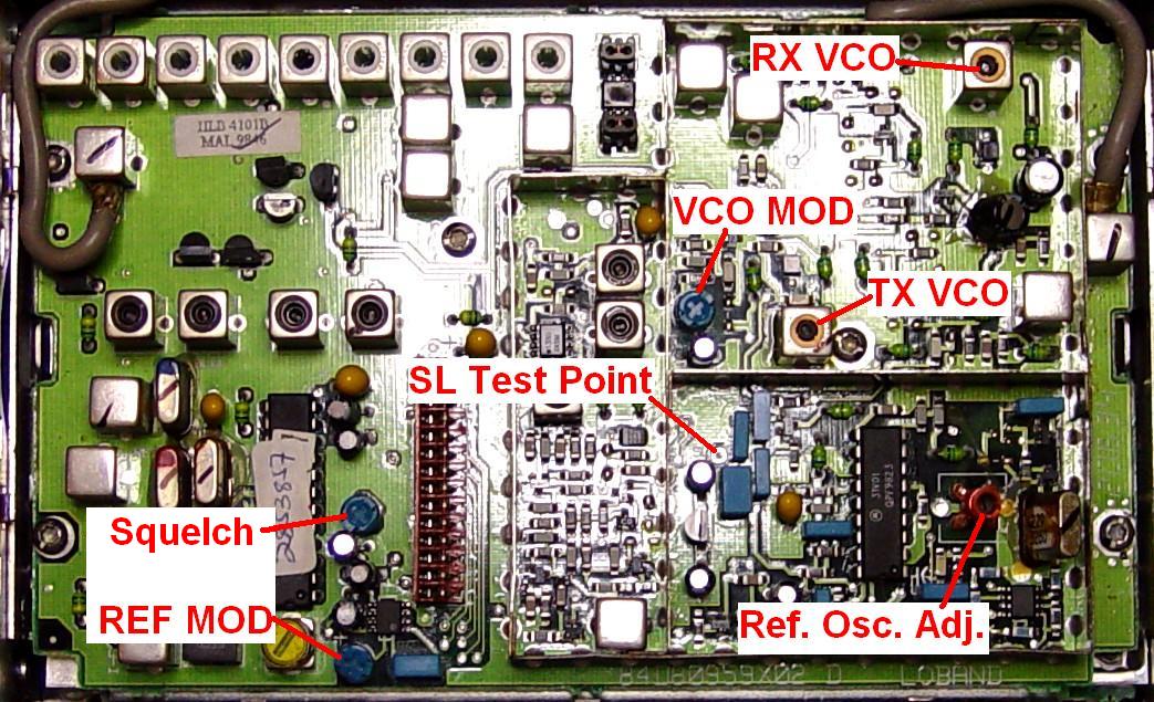
Here's a marked-up photo of a VHF-L RF board. Click on any of the photos for a larger view.
Here's a marked-up photo of a UHF RF board.

And here's a marked-up photo of a 900 MHz RF board.

Test Equipment and Setup:
You'll need a lot of equipment, most of which can be found in a decent service monitor. I have separate pieces of test equipment so I'll list the capabilities here. A computer with the appropriate RSS for your radio, a RIB, and a radio cable are always necessary.
Remove the radio's covers and take the shields off the RF board. Read the existing code plug and save that to disk. Program three channels, all simplex, all with carrier squelch and no PL or DPL. Determine the lowest and highest frequencies for the radio band you're working on, and program one channel to the lowest frequency, one channel to the highest frequency, and one channel somewhere in the middle that has all zeroes after the decimal point (i.e. it's an exact MHz frequency). For 800 or 900 MHz radios, choose a transmit frequency in either the normal (repeat) or the talk-around band.
Adjustments:
These procedures assume that the radio is otherwise working properly and has been initialized by the factory or been blanked and initialized by following the steps in the RSS manual. This implies the correct crystal and tuning data has been entered.
These adjustments should be performed in the order they're listed below.
At the conclusion of making these adjustments, you should go back into the Alignment menu and adjust the overall deviation and frequency. It might be worthwhile to go through the Board Replacement procedure and adjust all the deviation settings
Demodulated Audio Oscilloscope Traces:
Here is what a properly adjusted radio looks like with a 200 Hz sine-wave signal fed into the MIC audio at 0.7Vrms. Note that the top and bottom straight parts of the waveform are flat and level. The vertical deflection is 2 kHz per division, so the radio is deviating just over ±4.5 kHz.
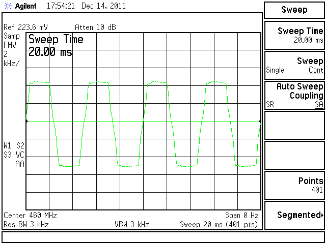
When the REF MOD pot was turned too far one way, the top and bottom flat areas are now tilted and no longer level.

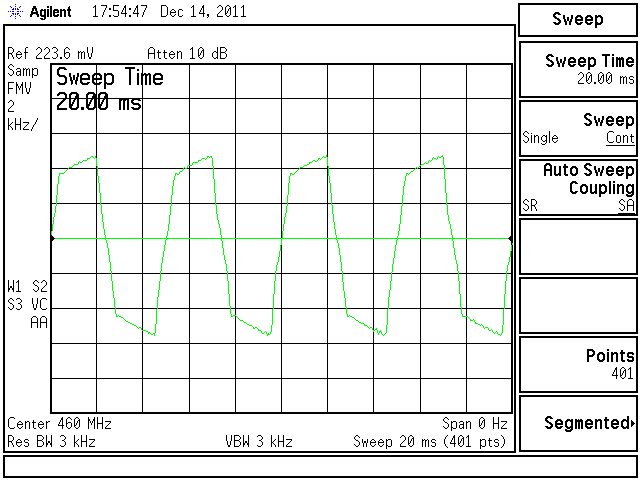
Similarly, when the REF MOD pot was turned too far the other way, the top and bottom flat areas of the waveform are now tilted the other way.
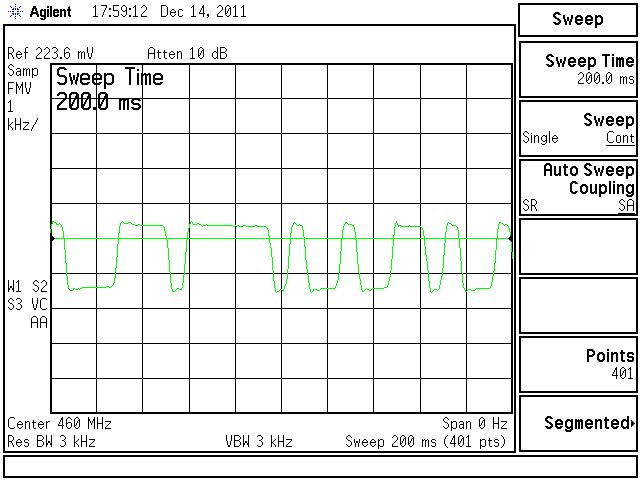
This is a DPL 445 signal after proper adjustment of the REF MOD pot. Note how the top and bottom straight parts of the waveform are flat and level. The vertical scale is now 1 kHz per division, so the deviation is just under ±1 kHz.
And for completeness, here's a 100.0 Hz PL signal coming out of the same radio. The vertical scale is now 1 kHz per division, so the deviation is just under ±1 kHz.
Other Items You Really Shouldn't Fool With:
The receiver detector coil is located in the left front of the RF board in the area near the squelch potientometer. It is usually painted yellow and can be adjusted for minimum received audio distortion, however this is not recommended unless someone has already messed it up. Feed a 3 kHz deviated tone, modulated at 400 or 1000 Hz, into the antenna jack at a 1mV level, connect an oscilloscope or distortion meter to the speaker output, and slowly adjust the detector coil for minimum distortion and maximum amplitude.
There is no adjustment for the receiver frequency; the second oscillator crystal governs the receiver frequency relative to the synthesizer's frequency. If you believe the receiver is off frequency, this crystal is most likely defective. It's hard to actually measure how far the receiver might be off frequency, and if it's within a kiloHertz or two, that's as good as they get.
Acknowledgements and Credits:
The component identification came from the MaxTrac service manuals. Additional procedural information came from the GM300 service manual and experimentation.
The REF MOD procedure was actually copied from the Motorola R100 UHF Repeater manual.
Contact Information:
The author can be contacted at: his-callsign [ at ] comcast [ dot ] net.
Back to the top of the page
Up one level (MaxTrac index)
Up one level (Motorola index)
Back to Home
This page created on Wednesday 14-Dec-2011.
Article text, artistic layout, photographs, images, and hand-coded HTML © Copyright 2011 by Robert W. Meister WA1MIK.
This web page, this web site, the information presented in and on its pages and in these modifications and conversions is © Copyrighted 1995 and (date of last update) by Kevin Custer W3KKC and multiple originating authors. All Rights Reserved, including that of paper and web publication elsewhere.