Motorola index
Back to Home
By Robert W. Meister WA1MIK

|
Maxtrac Index Motorola index Back to Home |
An Analysis of the MaxTrac Audio Click When PTT Is Released By Robert W. Meister WA1MIK |
|
Background:
Some MaxTrac and Radius radios (and MaraTracs, which use the same logic board inside) have a very noticeable "cli-click" on their signal when the PTT button is released, during the time when the PL reverse-burst is being sent out. This can be annoying, especially when one radio does it and another does not. My main UHF repeater was quiet, but the backup had the click problem. When I replaced the transmitter (a Radius radio driving an external amplifier) in the backup repeater, the click went away. This very noticeable difference prompted me to find out why.
I decided to trace the transmit audio through the logic board to see where it was coming from, and if anything could be done about it. The entire transmit audio chain is DC-coupled, so a slight DC spike somewhere will eventually modulate the transmit signal.
I tried this experiment with several radios to see if I could find which ones have the problem and which ones don't, then I'll try to figure out what's different among them.
Test Conditions:
I connected the subject radio to a dummy load and used a clip lead to ground the PTT line at the control head's MIC jack. The rising edge of the PTT signal was the trigger for all traces and occurs at two divisions from the left edge of the screen. This is seen as the Channel A (red) trace. The Channel B (blue) probe sampled all the other signals as noted below each trace. The input bandwidth for both channels was 10 kHz; this gets rid of high-frequency noise due to the use of a 200 MHz Fluke 199C oscilloscope. The sweep time was 50 mSec per division and the sensitivity can be noted in the boxes at the bottom of the display. The Channel B (blue) trace is the only one that would change between traces.
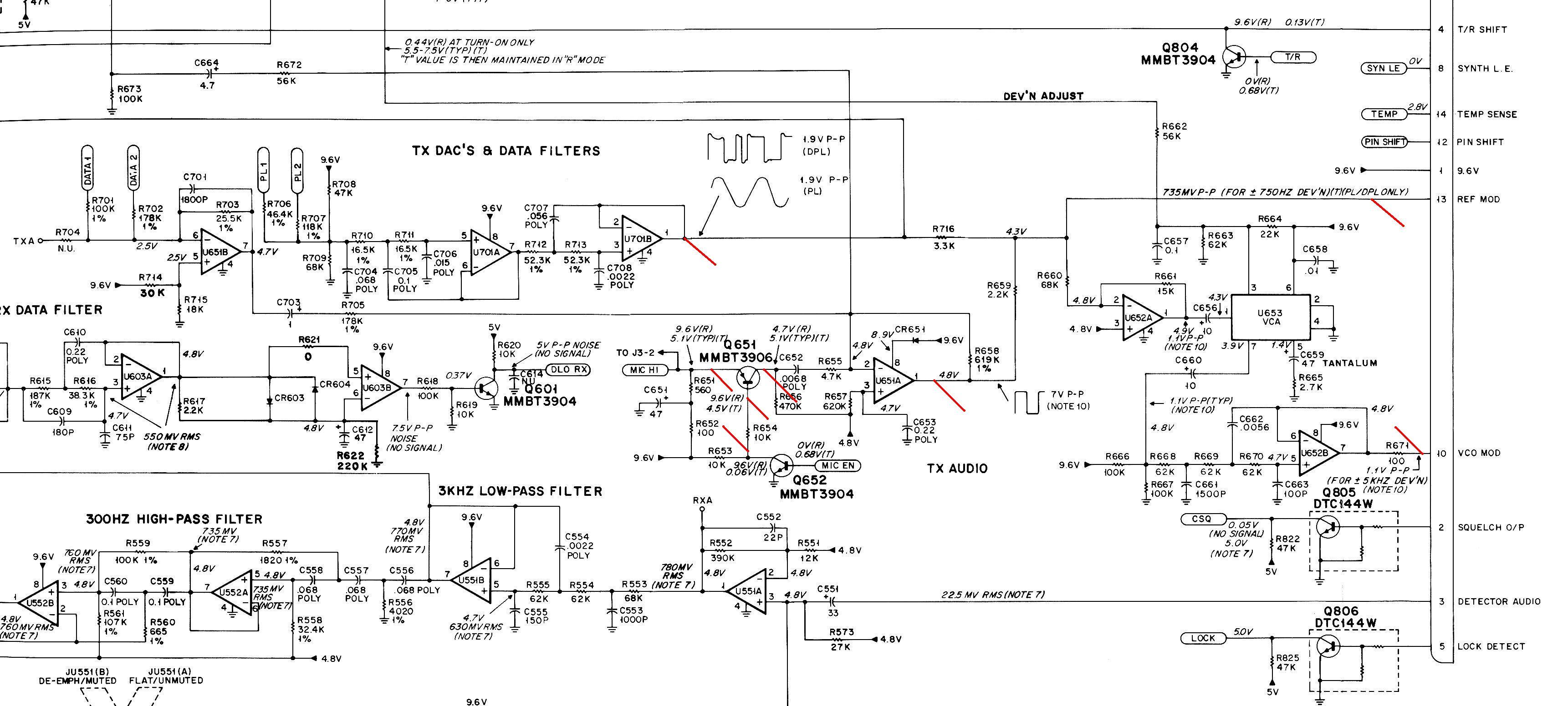
Transmit Audio Circuit:
Here's a portion of the MaxTrac transmit audio schematic. The various points measured with the scope are flagged with a diagonal red line. Low-speed (PL/DPL) data runs through U701A and U701B. Microphone audio runs through the MIC Gate Q651, which is enabled by the MIC Enable Q652, and then passes through the Limiter U651A. These two signals merge with the high speed (MDC) data and feed pin 13 on the connector going to the RF board (REF Mod). This same audio runs through U652A, then the Voltage Controlled Amplifier U653 to control the deviation level, and eventually out to pin 10 on the RF board connector (VCO Mod). Transmit audio thereby leaves the logic board on two pins that feed the RF board: VCO Modulation (primarily voice audio and high-speed data) and REF Modulation (primarily PL tone and DPL data) to aid the low-frequency response of the transmitter. Click on the image below for a larger view.
A Noisy Radio:
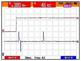
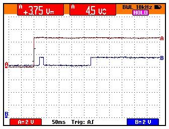
Starting at the logic board outputs, I grounded the PTT line, then released it and captured the following single-sweep traces. These are from a 45w UHF Radius radio.
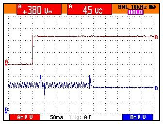
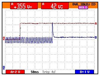
screen01 - logic/RF board pin 13 (REF Mod)
Spike 30 mSec after PTT released, and another one at 50 mSec.
screen03 - logic/RF board pin 10 (VCO Mod)
Spike at 30 mSec and 50 mSec after PTT released.
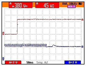
screen04 - U701 pin 1 (TX PL signal)
No real spike can be seen here. Notice the slight change in phase 50 mSec after PTT
released. This is the beginning of the reverse-burst, which lasts 180 mSec. The PL tone
frequency is 100.0 Hz, so one cycle takes 10 mSec. This makes it convenient to display
on the scope. Note that prior to the reverse-burst, the positive peaks of the cycles line
up exactly with the dots on the display graticule. During the reverse-burst, the negative
peaks of the cycles almost line up with the dots on the display graticule. This shows that
the phase has changed nearly 180 degrees; the actual spec is 120 degrees of phase
shift but you can't tell that from this scope trace.
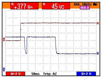
screen05 - U651 pin 1 (MIC audio signal)
Here's where we see real big spikes. So the problem is originating in the MIC audio
chain, not the PL/DPL circuitry.
screen06 - Q651 collector (MIC gate)
Both edges of this spike make their way through U651 to the RF board, producing the
audible click.
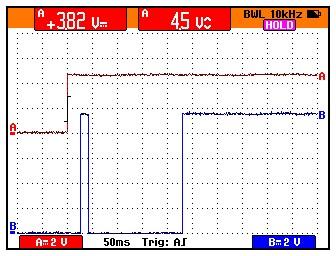
screen07 - Q652 collector (MIC enable)
For some reason, the microphone is disabled 30 mSec after PTT is released, but then
enabled when the reverse-burst starts. I would expect the mike to be disabled so audio
does not interfere with any pre- or post-MDC signaling. In this case however, it gets
re-enabled, which makes no sense.
screen08 - Q651 emitter (MIC gate)
screen09 - Q651 base (MIC gate)
screen10 - Q651 emitter (MIC gate with microphone)
Things are slightly different with a microphone plugged in. Most mikes have a built-in
preamp which draws some current from the radio. There's some bias voltage provided
for just this purpose, via R651 and R652. The PTT switch in the microphone closes the
mike audio circuit (powering the preamp) as well as the PTT line when pushed. This
produces the 5.2VDC you see on the blue trace at the left side of the screen. When the
PTT button is released, the mike preamp is disconnected, so the voltage on this line
rises to 8.8VDC. Shortly afterwards, the enable signal allows this point to rise to
9.6VDC.
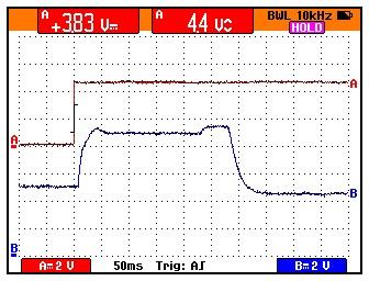
screen11- Q651 base (MIC gate with microphone)
screen12 - Q651 collector (MIC gate with microphone)
This signal eventually runs through U651 and out to the RF board as modulation audio.
The initial rise when PTT is released is caused by the mike preamp being disconnected.
The spike that occurs 20 mSec later is caused by the mike enable signal. The normal
resting voltage is finally reached after the transmitter is shut off, at the conclusion
of the reverse-burst, at about 230 mSec after PTT is released.
A Quiet Radio:
I tried a few other UHF radios and they all had audible clicks. I came across one 5-pin VHF radio that was as quiet as a mouse. It has Radius 1.01 firmware in it. Here are some waveforms from that radio.
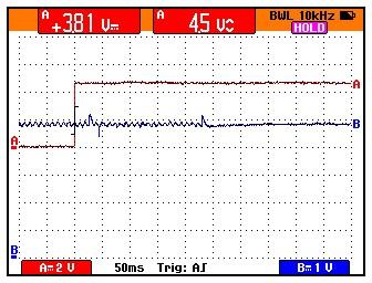
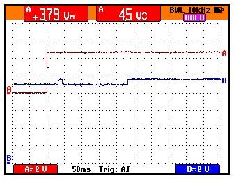
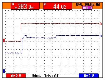
screen21 - logic/RF board pin 13 (REF Mod)
100.0 Hz PL tone, no click at all. Compare this to screen01.
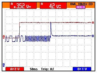
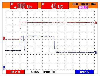
screen22 - logic/RF board pin 13 (REF Mod)
331 DPL code, then the 134.4 Hz turn-off tone. No click at all.
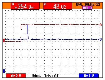
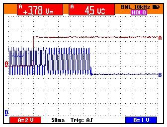
screen23 - logic/RF board pin 13 (REF Mod)
Carrier squelch, no click at all except when the transmitter shuts off about 40 mSec after
PTT is released.
Now let's look at the microphone electronics to see if this radio has any of the characteristics of the previous one.
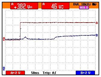
screen24 - U651 pin 7 (MIC audio signal)
No click at all except when the transmitter shuts off. Compare this to screen05.
screen25 - Q651 collector (MIC gate)
No click at all. Just a clean shift in level when the transmitter shuts off. Compare this to
screen06.
I plugged the same microphone into the radio as before and measured a couple more points.
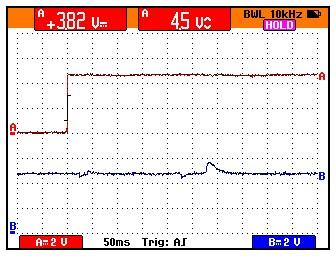
screen26 - Q651 collector (MIC gate with microphone)
Note that the output of the MIC gate rises as soon as PTT is released, and stays that
way during the entire reverse-burst time. This is because the PTT switch disconnects
the microphone preamp, removing the load on the MIC input to the radio. Compare this
with screen12.
screen27 - Q652 collector (MIC enable)
Note that the MIC gate is enabled the entire time the radio is transmitting. Compare this
with screen07. This particular radio happens to be a 5-pin logic board, and probably
does NOT have any signaling or MDC capabilities. Because of this, there's no need to
mute the microphone during the reverse-burst time. It would seem that the MIC gate
could therefore remain active during the reverse-burst time, and this suggests a fix to
the other radios that have the click problem.
Possible Fixes or Work-Arounds:
Possible fixes to MaxTrac/Radius radios are listed below in preferential order:
Fix #1:
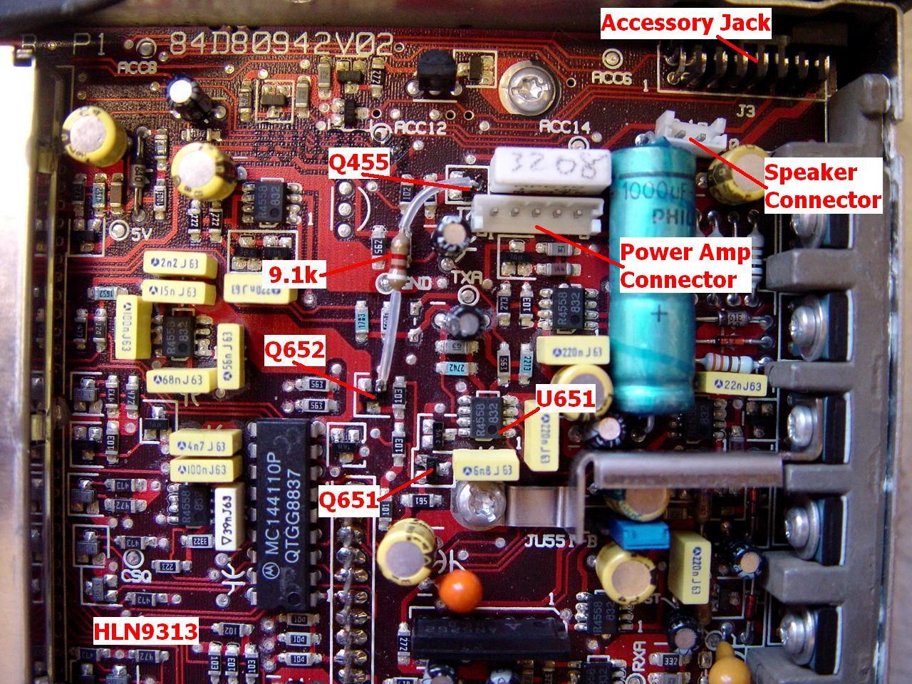
I tried adding a 9.1k 1/4w resistor from Q652 base to the switched transmit 9.6VDC signal, Q255 collector. This turns on Q652 whenever the radio is transmitting, which keeps the MIC enable and MIC gate transistors enabled the whole time, regardless of what the microprocessor tries to do to disable them. It completely eliminates the click when the PTT button is released. The following trace shows the resulting waveform.

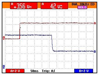
screen31 - Q652 collector (MIC enable)
This signal remains active low during the entire reverse-burst time, just like it does
on a radio that does not have this problem. Compare this to screen27. The various other
signals points look just like they did on the "quiet" radio.
Here's a photo showing this modification on a 9313 logic board. Click on the image below for a larger view.
Fix #2:
I tried adding a 10uF 35V axial electrolytic capacitor from Q651 base to ground in an attempt to slow down the switching transients. This seems to yield about a 50 mSec delay in activating and muting the microphone input. It reduces and nearly eliminates the click when the PTT button is released. The following traces show the modified waveforms.
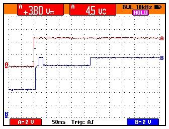
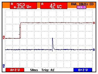
screen13 - logic/RF board pin 13 (REF Mod)
The glitch due to the DC shift of Q651 is completely gone. Compare this to screen01.
screen14 - Q651 base (MIC gate)
The pulse has been softened considerably, resulting in much less DC shift on the output
of the gate and subsequently from U651. Compare this to screen09.
screen15 - Q651 collector (MIC gate)
The pulsed off/on at 20 mSec has been eliminated. Note the rise and fall time due to the
capacitor on the base. Compare this to screen12.
screen16 - U651 pin 1 (MIC audio signal)
The big spikes are all gone. You can barely see a pulse at 20 mSec after PTT is
released. Compare this to screen05.
Summary:
So far, my 45w 5-pin MaxTrac does NOT have the click, but my 45w 16-pin MaxTrac does. A 25w 5-pin Radius with a masked (no EPROM) logic board does NOT have the click, but a 45w 16-pin Radius (the one used to produce the first 16 screens) does. A low-band MaraTrac with a 5-pin board had the click. The following table summarizes the features of the various radios I could test:
|
Logic boards come in several varieties, described below. Any of the board model numbers can have an A, B, or C suffix. All of the boards except the MASKED version have the microprocessor and memory components enclosed within a shielded area. The additional memory IC sits underneath the EPROM, between the rows of socket pins. Some radios may have PROMs while others have ultraviolet-erasable (UV) EPROMs to hold their firmware.
|
Conclusions:
It would seem from my limited supply of radios, that some of the 5 pin logic boards do NOT have this problem, while all of the 16-pin logic boards do. It may be a combination of firmware, features, and logic boards. Since the easiest fix is the addition of one resistor, this is what I recommend. The locations needed will vary depending on the logic board model; the best way to figure out where to connect it is to consult the service manual and look at the appropriate schematic and board layout.
I did try several different configurations with one 16-pin radio that had the problem; I could not eliminate the clicking. There's a version of Radius firmware that provides channel-steering via the 16-pin accessory connector; if I can find that version, I'll give it a try.
I had a 16-pin 800 MHz radio with V5.21 firmware that had the click, but when I put the V4.00 firmware into it (which came out of a 5-pin radio that did not have the click), the click was NOT present in the radio after blanking and initializing it. Unfortunately, the radio did not have enough memory for signaling, so I could not check if MDC was a factor. It may be that all firmware later than Version 5 has this problem.
Extra Credit Bonus Section:
While I had the scope attached, I took a snapshot of the PL when it begins its reverse-burst phase shift, seen here at exactly 50 mSec after PTT is released:
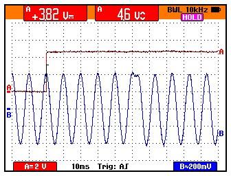
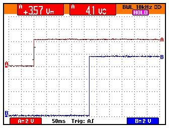
screen32 - logic/RF board pin 13 (REF Mod)
Note that the positive peaks of the sine waves are lined up with the graticule before the
reverse-burst begins, then they're shifted between 3 and 4 divisions during the
reverse-burst part. This represents 30% to 40% of 360 degrees, or 108 to 144 degrees. Closer
analysis by the scope's software shows that there is 23.3 mSec between the positive
peak just prior to the reverse-burst (in the middle of the screen at 4 divisions past the
release of PTT) and the positive peak of the first full cycle after the reverse-burst. Since
each cycle takes 10 mSec, the actual phase shift is 3.3 mSec, or 33% of 360 degrees,
or 118 degrees. The Motorola reverse-burst specification is 120 degrees, which would
be equivalent to 33.3333%. Sorry, my equipment just isn't accurate enough to resolve
that small difference.
Interesting Anecdote or Side-Effect:
I was driving home the other night and talking on the repeater. The other station turned the conversation over to me, so I pressed the PTT button on the microphone and proceeded to talk for about a minute. When I released the PTT button, I did NOT hear the usual courtesy beep. I looked down at the radio and saw it was on but no signal was being received. I waited a few seconds and rekeyed the radio; nothing heard from the repeater. I thought, "Oh great, the power supply blew out (again). We just had our first real snow storm of the season and I can't easily get up to the repeater to fix it. Oh well."
30 seconds later I heard a courtesy beep. "That's strange." I thought. "How did the machine fix itself?" Then the other station came on and asked if I was still there. I pressed the PTT button and noticed that I was still hearing crackles on the radio as I passed through a noisy spot. I thought "Wait a minute; MaxTracs are NOT full-duplex radios. What's going on?" I pressed the button again and this time saw the TX LED turn on solidly on the front panel. We continued our conversation until I got home, but I had to check that TX LED each time.
It turns out the PTT switch inside the microphone (an HMN1056D that's not repairable) was intermittent. When I pressed it the first few times, I expected, naturally, that the radio was transmitting, but the received signal was so quiet, and without that cli-click, I never heard the radio squelch up when the repeater shut off after the hang time, while I was talking and still had the PTT button pressed. Sometimes those extra clicks as the transmitter shuts off ARE useful.
I have since purchased a new microphone!
Credits and Acknowledgements:
The partial schematic of the logic board came from the official Motorola MaxTrac Detailed Service manual.
MaxTrac, Radius, MaraTrac PL, DPL, and probably a bunch of other terms are trademarks of Motorola, Inc.
Contact Information:
The author can be contacted at: his-callsign [ at ] comcast [ dot ] net.
Back to the top of the page
Up one level (Maxtrac Index)
Up two levels (Motorola index)
Back to Home
This page originally posted on Wednesday 08-Nov-2006
Photographs, oscilloscope traces, article text, and hand-coded HTML © Copyright 2006 by Robert W. Meister WA1MIK.
This web page, this web site, the information presented in and on its pages and in these modifications and conversions is © Copyrighted 1995 and (date of last update) by Kevin Custer W3KKC and multiple originating authors. All Rights Reserved, including that of paper and web publication elsewhere.