Motorola index
Back to Home
Out of a MaxTrac 5-pin Radio
By Scott Withrow KC9LQV

|
MaxTrac index Motorola index Back to Home |
Getting Discriminator (Flat) Audio Out of a MaxTrac 5-pin Radio By Scott Withrow KC9LQV |
|
I'm a railroad fanatic. I enjoy observing railroad track switching and control signals that use radio systems on 896 and 935 MHz called ATCS (Advanced Train Control System). Motorola 800 MHz MaxTrac radios can easily be used to receive the 896 MHz signals and 900 MHz MaxTrac radios will directly tune 935 MHz, however as I found out, not all MaxTracs are created equal. The computer programs that monitor and decode these signals need discriminator (or flat) audio. Only those radios with a 16-pin accessory jack can be configured to provide a discriminator audio output. Radios that have 5-pin accessory jacks are lacking the circuitry and an available pin to provide such a signal.
With help from Bob WA1MIK, I recreated the circuitry in the 16-pin logic boards to give me a discriminator audio output identical to what was present in those boards. I made a small circuit board to hold the parts and stuffed it up inside the control head in place of the loudspeaker. I also mounted a 1/8 inch (3.5mm) headphone jack on the side of the control head to allow for easy connection to a computer sound card. This article shows the circuitry, my board, and installation in an 800 MHz MaxTrac radio that has an HLN5172 logic board, most commonly found in trunking radios.
While Scott's purpose was for monitoring ATCS signals, this same modification can be used for repeater receivers where flat (discriminator) audio is required.
The Circuit in the 16-pin Radios:
The receive audio is processed on the logic board underneath the radio. The audio comes in at the right side of this schematic diagram from pin 3 of the connector that goes to the RF board. It exits the board through JU551 and appears on pin 11 of the 16-pin accessory connector at the rear of the radio.
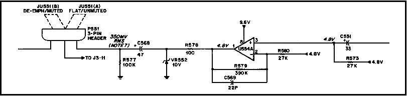
None of these components are present on any of the 5-pin logic boards. All I did was duplicate this circuitry on a small external circuit board and provide a more convenient output jack.
Note that C568 is marked incorrectly on the schematic but it is marked correctly on the X-ray view (the negative end goes to JU551 pin "A"). The positive end should go towards U554 pin 1.
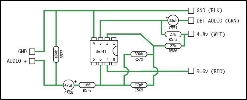
My Circuit:
Here's the schematic I ended up with. Note that the component identifiers and values were taken directly from the 16-pin schematic shown above. The only differences are that I used a single uA741 op-amp instead of one half of the dual op-amp (U554A) used on the MaxTrac logic board, and I eliminated VR552, which was deemed unnecessary.
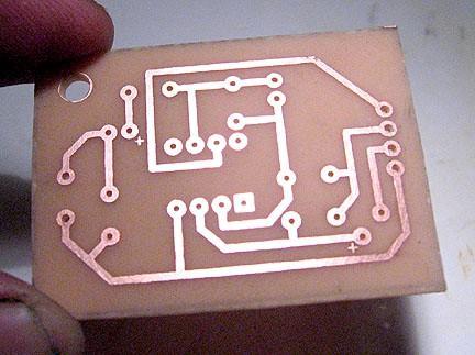
I designed and made my own circuit board. Here's a picture of the copper traces on the underside.
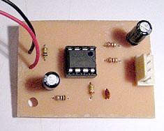
Here's a photo of the top of the board with the components installed.
Connecting It To The MaxTrac:
The board needs four input signals and provides an output signal that includes its own ground, so you can run separate wires to the output jack. These are detailed below.
| Signal Name and Wire Color | Where To Get It |
|---|---|
| GND (BLK) | J6 pin 11 |
| DET AUDIO INPUT (GRN) | J6 pin 3 |
| 4.8V (WHT) | See the text below |
| 9.6V (RED) | J6 pin 1 |
| AUDIO+ OUTPUT | To output jack |
| GND OUTPUT | To output jack |
J6 is the row of 14 pins that make the connection to the RF board on the other side of the chassis. Pin 1 is closest to the center of the board. This photo shows the three wires (BLK, GRN, RED) soldered to this connector.
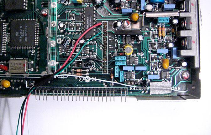
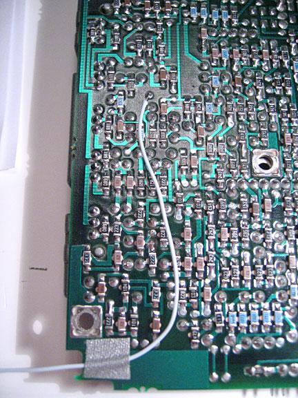
4.8V is generated by U401 and is available in many spots. Unfortunately none are easily accessible. Rather than risk shorting out some pins by soldering to ICs on the top of the board, I removed the logic board and attached a wire to an isolated pad at U401 pins 6 and 7. You may have to refer to the detailed service manual to find this spot, or another suitable point, on your logic board, as they're all different. The photo below shows this connection for the WHT wire. The five power transistors and heat sink are at the left side of this photo.
I had already removed and modified the RF board by shorting out the two front-end filters and shorting out Q205. This made removal and reinstallation of the logic board a lot easier.
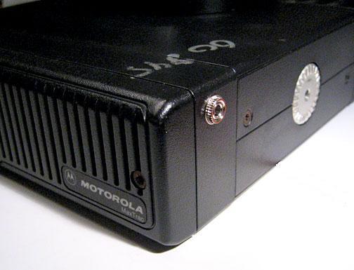
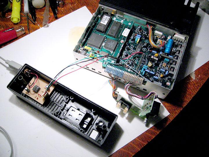
I removed everything from the control head and drilled a small hole on the side to mount the output jack. The loudspeaker will not be reinstalled. See the photo below.
The circuit board was mounted into one of the existing speaker mounting holes using the leftover hardware. The photo below shows the circuit board mounted in the control head with the jack yet to be installed in its hole.
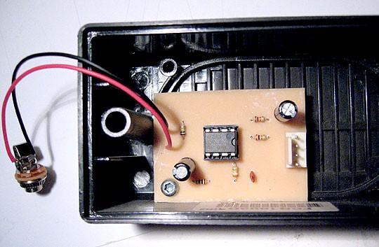
I'd already attached the wires to the logic board and tested the voltages, so once I had the board built, I was immediately ready to fire it up. I used a 4-pin connector to make it easily detachable. Testing could easily be done on the bench. See the photo below that shows a previous revision circuit board.
The Results:
Well, it took me most of forever to get it finished (a couple of months), but finished it is. And it worked like a charm. The audio level coming out of the new board is almost identical to the level I get from the 16-pin boards. It's very usable for ATCS purposes.
This has been a fun project, and I really feel like it's taught me a lot. Not to mention that I can now use the cheaper and more plentiful 5-pin boards in my ATCS radios.
Acknowledgements and Credits:
Motorola schematics came from the MaxTrac Detailed Service Manual.
Motorola and MaxTrac are trademarks of Motorola, Inc.
Additional information about the ATCS system can be found at: www.atcsmon.com.
Thanks to Bob WA1MIK for helping me with the design and for turning this collection of notes and photos into an article.
Contact Information:
The author can be contacted at: his-callsign [ at ] gmail [ dot ] com.
Back to the top of the page
Up one level (MaxTrac index)
Up two levels (Motorola index)
Back to Home
This page originally posted on Thursday 17-Mar-2011
Article text and photographs © Copyright 2011 by Scott Withrow.
Additional text, layout, conversion to a Repeater-Builder article, and hand-coded
HTML © Copyright 2011 by Robert W. Meister WA1MIK.
This web page, this web site, the information presented in and on its pages and in these modifications and conversions is © Copyrighted 1995 and (date of last update) by Kevin Custer W3KKC and multiple originating authors. All Rights Reserved, including that of paper and web publication elsewhere.