Motorola index
Back to Home
5-pin Logic Boards on
MaxTrac/Radius Radios
By Robert W. Meister WA1MIK

|
MaxTrac index Motorola index Back to Home |
Adding Flat TX Audio to 5-pin Logic Boards on MaxTrac/Radius Radios By Robert W. Meister WA1MIK |
|
The 16-pin logic boards already have a provision on the 16-pin Accessory Connector for microphone audio on pin 2 or flat TX audio on pin 5. The 5-pin logic boards have no external microphone audio input, so the only way to feed audio into these radios is to use the front-panel RJ45 microphone jack pin 5 or wire up a cable and let it hang out of the radio. There has to be a better way, and there is.
There are two spare pins on the front-panel RJ45 jack. I have chosen to use pin 2 for a flat TX audio input. This pin is wired all the way through to the logic board J8 pin 9, where it is unused and available. J8 pin 10 is ground.
You will need a 100k 1/4w resistor, a 56k 1/4w resistor, and a 4.7-10uF 25V (or higher) electrolytic capacitor. These duplicate the components used on the 16-pin logic board; a piece of that board's schematic diagram is here as a 100kb PDF file. You merely have to add these parts to the 5-pin logic board and wire them accordingly.
The 100k resistor gets installed between J8 pin 9 and J8 pin 10. You will need to add another component to the lead that goes to J8 pin 9. I formed the resistor into a U-shaped loop and put the resistor body close to pin 10, so the pin 9 lead was exposed. Make sure you solder the component to the inside edge of the contact after the 90 degree bend, so it doesn't interfere with the control head connectors. See the photo below. Click on it for a larger image. (Pay no attention to the other modifications on the board; they're for manual power control, manual deviation control, and PL deviation reduction.)
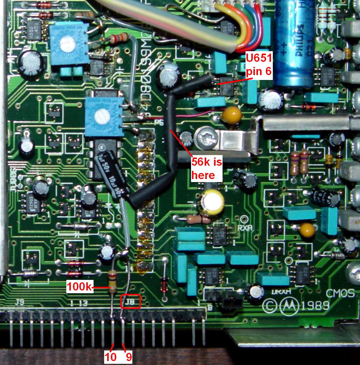
I used a short piece of Teflon sleeve over the negative lead of the capacitor and attached that lead to the resistor lead going to J8 pin 9. I shortened the positive lead of the capacitor and one lead of the 56k resistor and soldered them together. I slipped some heat-shrink tubing over the resistor and spliced connection but chose not to actually shrink it; it's just there for insulation. The remaining lead of the 56k resistor goes to U651 pin 6. Some boards have a convenient feed-through hole just to the left of pin 6; that's what I used but it's not visible in the photo above. If not, you can tack-solder the resistor lead to U651 pin 6 directly.
The sensitivity at either the microphone audio input or the flat TX audio input is about 50mVAC per kHz of deviation with a 400 Hz tone. The microphone audio input has pre-emphasis, which will increase the level of higher frequencies at a 6dB per octave rate. The flat TX audio input is inserted AFTER this pre-emphasis, which is what makes it "flat".
You can perform this same modification on a MaraTrac, except there's no spare pin on the internal RJ45 connector, so you may have to get creative.
Now, if only these radios had a flat and MUTED RX audio output...
Acknowledgements and Credits:
MaxTrac, Radius, MaraTrac, and lots of other terms are trademarks of Motorola, Inc.
Schematic information came from the MaxTrac Detailed Service Manual.
Contact Information:
The author can be contacted at: his-callsign [ at ] comcast [ dot ] net.
Back to the top of the page
Up one level (MaxTrac index)
Up two levels (Motorola index)
Back to Home
This page originally posted on Thursday 12-Sep-2019
Article text, photographs, artistic layout, and hand-coded HTML © Copyright 2019 by Robert W. Meister WA1MIK.
This web page, this web site, the information presented in and on its pages and in these modifications and conversions is © Copyrighted 1995 and (date of last update) by Kevin Custer W3KKC and multiple originating authors. All Rights Reserved, including that of paper and web publication elsewhere.