MaxTrac index
Motorola Index
Back to Home
MaxTrac or MaraTrac Mobile radio
By Scott Withrow KC9LQV

|
MaraTrac index MaxTrac index Motorola Index Back to Home |
Replacing the Dallas Memory Device in a MaxTrac or MaraTrac Mobile radio By Scott Withrow KC9LQV |
|
Many MaxTrac, Radius, and MaraTrac mobile radios use the same logic board, and the older boards (probably pre-1992) used a Dallas DS1220 Non-Volatile Random Access Memory (NVRAM) module. This is just a regular static RAM that has a long-life battery embedded within the molded epoxy. That battery won't last forever and it seems that about 20 years is their lifetime. These modules are starting to go bad in 2011, resulting in lost program information, as some of the code plug data is stored within this device. Any radio that uses one of these Dallas modules is working on borrowed time. It's not a matter of "if"; it's a matter of "when". Read the code plug and save the archive because some day you will need it. Better to fix it while you still can.
The memory module is used by all MaraTrac radios and by MaxTrac and Radius radios if the code plug occupies 320 blocks. So your radio might not show the symptoms if the code plug data only occupies 64 blocks. The radio will hold its programming data as long as power is continuously applied, but once you disconnect the power source, the radio will forget everything you programmed into it. This article explains what you can do to fix the radio and get a lot more useful years out of it.
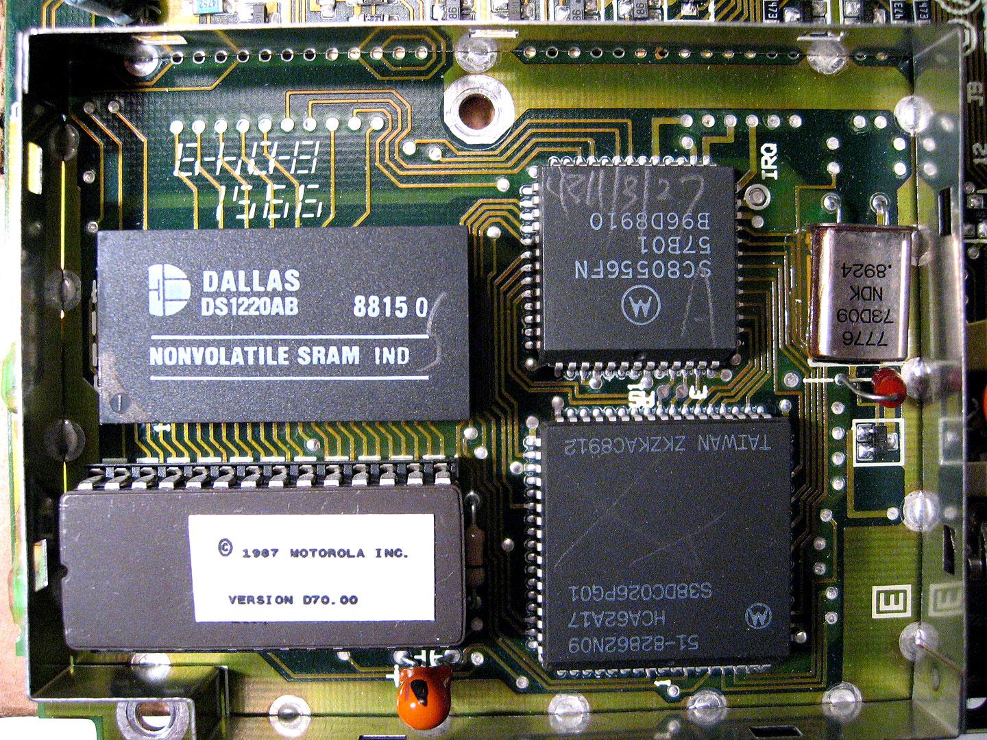
The memory module is housed under the logic board shield, along with several other ICs, including the microprocessor, an Application-Specific IC that expands the I/O capabilities of the CPU, and some other support components, all nicely soldered into the logic board. There's also a socketed EPROM that holds the firmware, and an additional small IC actually soldered inside the socket. The photo below shows the original Dallas module. Click on any of the photos for a larger view.
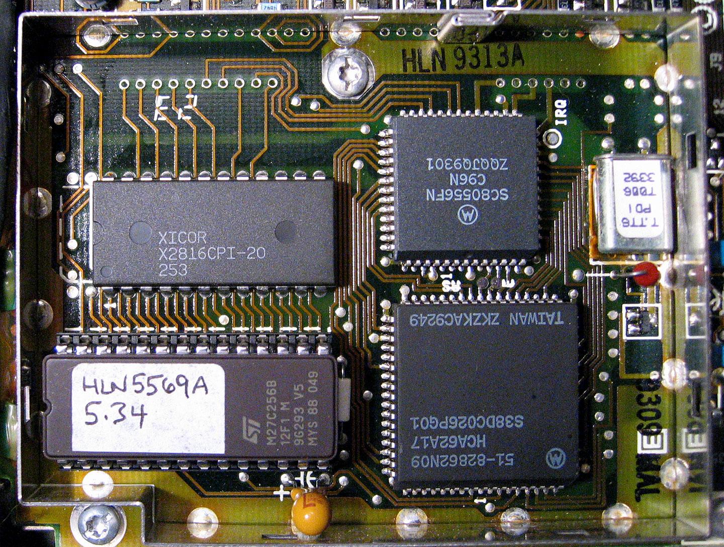
When the NVRAM battery voltage goes low enough, this problem will occur. I hear you saying: "Replace the battery." Well, you can't open the module; it's one big epoxy blob. Your only choice is to replace it with another Dallas DS1220 with a new battery that will last another 20 years, or replace it with a real parallel EEPROM that doesn't rely on a battery for memory retention. The newer logic boards all use a parallel EEPROM. The photo below shows a Xicor 200nS parallel EEPROM installed by Motorola.
What You'll Need:
You can either buy a new Dallas DS1220AB for about $8-$10US, or buy a 2kB by 8-bit (2Kx8) parallel EEPROM in a 24-pin wide Dual-Inline Package (DIP), commonly called a 28C16 for about $4-$8US. Get one that is at least 200nS or 150nS speed (-200 or -20, or -150 or -15 at the end of the part number) or faster. Additionally you may want to buy a 24-pin wide (0.6 inches) IC socket for about $1US. All of these parts can be bought on popular auction sites but be careful to make sure you get exactly the right parts. Either IC must be the standard 24-pin wide DIP packaging and 150nS or 200nS speed. Suggestion: the parallel EEPROM is physically shorter than the Dallas DS1220 and it will fit under the shield better. Also, if you get the parallel EEPROM, you'll never have to worry about the battery dying again.
You'll also need three Torx drivers: T15 to remove the dash-mount control panel or bottom plate of the MaraTrac, and T8 and T10 to remove the logic board. You'll have a much easier job removing and reinserting the logic board if you remove the RF board first, using the T10 driver. Unsoldering and soldering equipment will also be required, of course. Use whatever you're most familiar with.
Removing the Dead Device:
To replace the device, you must first remove it. Both the Dallas NVRAM and a replacement EEPROM are CMOS devices, as are many parts on the logic board, so be careful when handling them. Remove the logic board, unsolder the old Dallas device, and remove it from the circuit board. If you unsolder it properly and remove all the solder, it will fall out all by itself. Dispose of it properly. The pins are sharp; beware. Clean the holes in the circuit board. The photo below shows the board after this has been done. Note the outline where the chip goes as well as a pin 1 identifier (1).

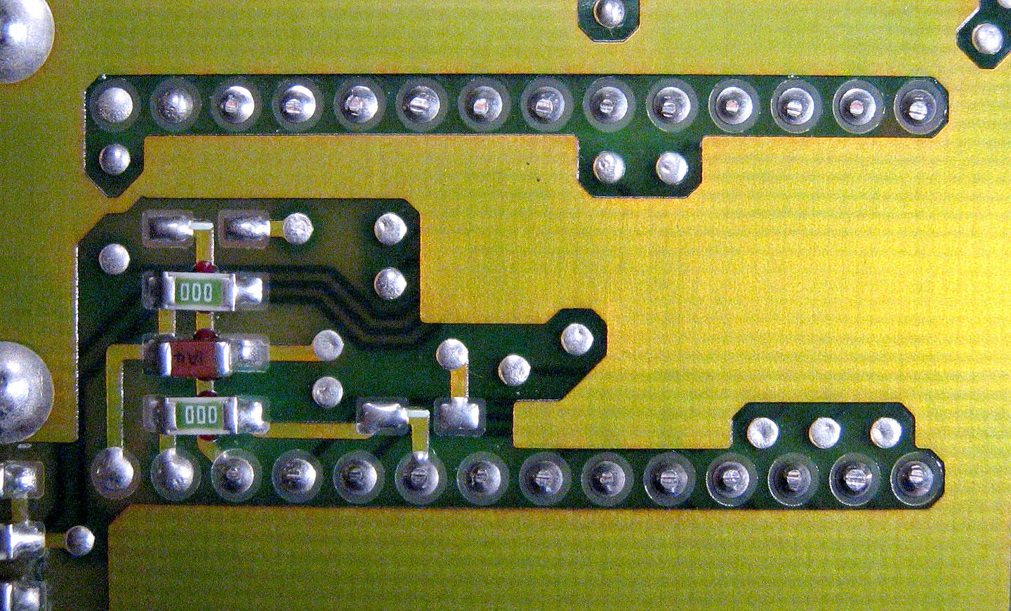
Clean the back of the board as well. The photo below shows the solder side of the same logic board before the Dallas part has been removed. Don't remove any of the nearby zero-ohm jumpers.
Installing the New Device:
Now you need to make a decision. You can install a 24-pin IC socket into which a new device will be inserted, or you can directly solder a new NVRAM or parallel EEPROM into the logic board. I chose to install the socket. Nothing special; I got one that was similar to the EPROM socket next to it but only had 24 pins. The photo below shows the socket soldered into the logic board. Note the small notch on the plastic at the left side of the socket that indicates the orientation (where pin 1 should go) of the new memory device.

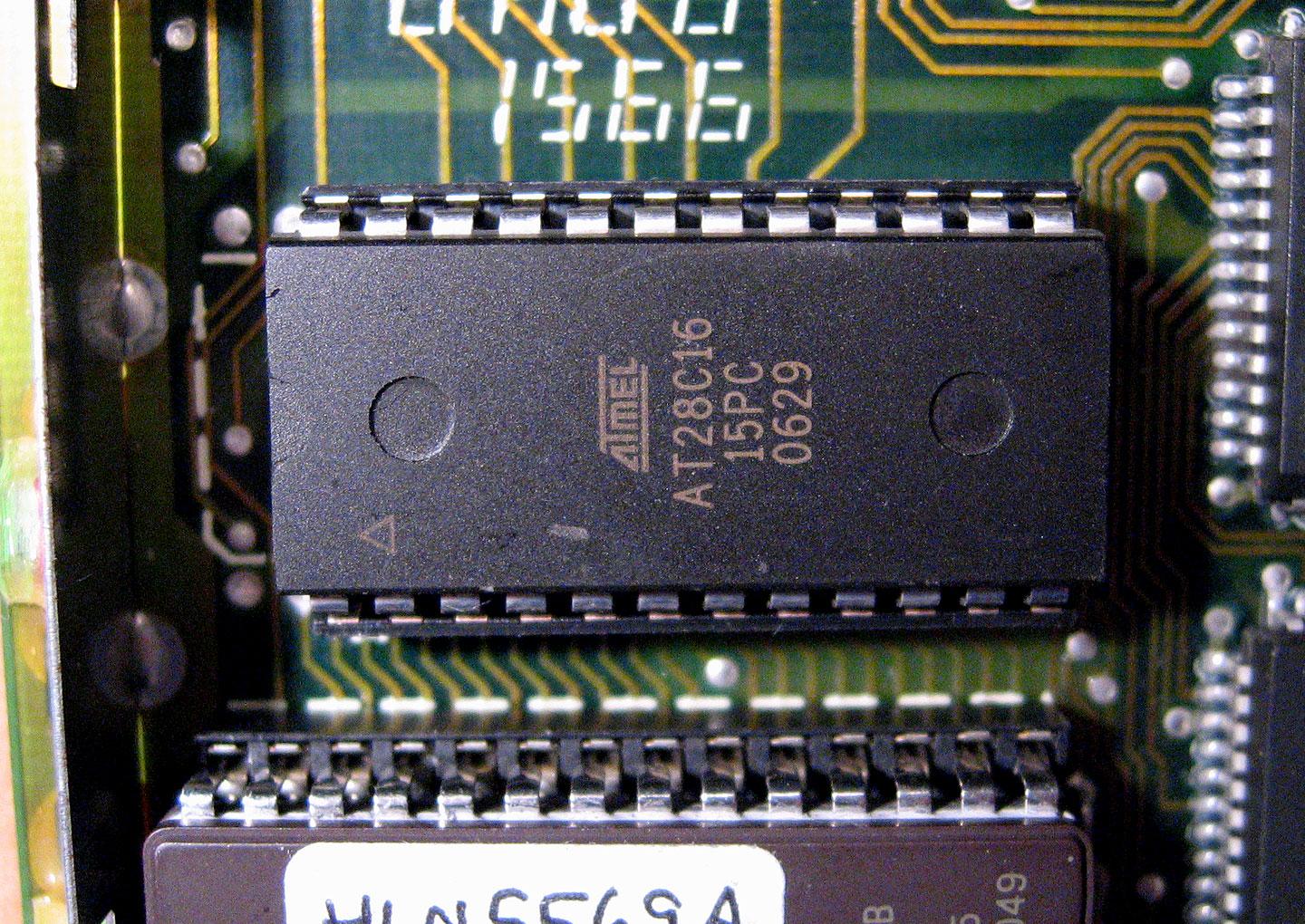
After cleaning the board, insert the new memory module into the socket (unless you elected to directly solder the new part into the logic board), reinstall the logic board (this is easier to do if you remove the RF board first), and finally reprogram the radio. The tuning data is held within the microprocessor's EEPROM, so it will remain intact. The photo below shows a new Atmel 150nS parallel EEPROM installed in the socket.
Simple. The whole job might take half an hour depending on your soldering skills. I actually did this to two radios; the second wasn't showing symptoms yet but I knew it would eventually.
Contact Information:
The author can be contacted at: his-callsign [ at ] gmail [ dot ] com.
All photos are by Scott Withrow are © Copyright 2012.
Article text, layout, and hand-coded HTML by Robert W. Meister WA1MIK.
Back to the top of the page
MaraTrac index
MaxTrac index
Motorola Index
Back to Home
This page originally posted on Tuesday 07-Aug-2012.
This web page, this web site, the information presented in and on its pages and in these modifications and conversions is © Copyrighted 1995 and (date of last update) by Kevin Custer W3KKC and multiple originating authors. All Rights Reserved, including that of paper and web publication elsewhere.