Up two levels (Moto index)
Back to Home
Repeater Experience
By Robert W. Meister WA1MIK

|
Up one level (MSF index) Up two levels (Moto index) Back to Home |
MSF5000 900 MHz Repeater Experience By Robert W. Meister WA1MIK |
|
Disclaimer:
The work performed on these stations is representative of what you can expect to do to any others that come from this same source. Jim N1GTL and I have probably spent 8-10 hours together to get four of the six in this condition. It's a learning experience for both of us. If you have everything you need ready to go (5 MHz HSO, U831, manuals, test equipment), you can probably get one station fully functional in 1-2 hours. Of course your mileage may vary, depending on your expertise, available test equipment, and prior experience.
History:
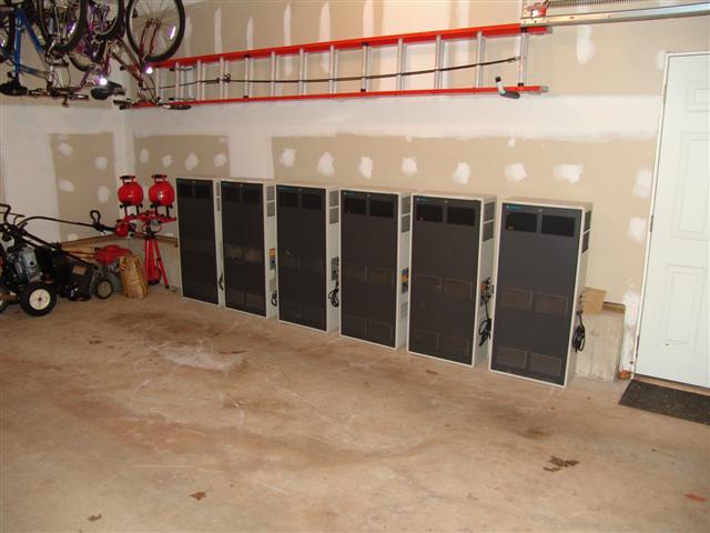
These stations were purchased Friday 15-Feb-08 by Jason WA1NH, who drove from New Hampshire, picking up I-95 near Boston MA, picking up Scott N1SEC as he made his way through Rhode Island, and into Connecticut, where he picked up my share of the money ($840) in New Haven around 12:30pm. He continued to New York, ending at the warehouse in New Jersey sometime around 3pm. He was still at the warehouse at 6pm, having loaded 27 repeaters onto the rented truck. His first stop was in White Plains NY around 8pm. He arrived back in New Haven CT around 10:45pm where we unloaded four stations into my GMC Canyon pickup truck (by the way, four stations lying on their left side fit exactly between the wheel wells of the truck, with about 1/4 inch to spare) and two more into Jim N1GTL's Ford Explorer. They then continued the trip, arriving in Attleboro MA around 1:15am Saturday to drop Scott off, and eventually back home around 6am, unloading stations as he went. All six of the stations ended up in Jim's heated garage where they will be worked on as time goes by. It was a very long day for Jason and everyone else.
Here's a photo taken by Jim N1GTL, of our six stations in his garage, all lined up with no where to go. We arbitrarily numbered the station cabinets and doors from 1 to 6, starting at the right.
What We Have:
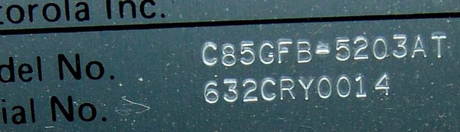
The above photo was taken by Jim N1GTL. The model number C85GFB-5203AT breaks down as follows:
| Value | Meaning |
|---|---|
| C | Compa-Station Cabinet |
| 8 | 150 watts |
| 5 | 806-960 MHz |
| GF | Analog Plus (896 MHz) |
| B | 120VAC Base Station |
| 5 | Connect Tone (trunking) |
| 2 | 12.5 kHz Spacing |
| 0 | 1-16 Channels |
| 3 | Local Control (trunking) |
| A | First Revision |
| T | Repeater |
According to the service manual, these stations are assembled with the following items or assemblies:
| Qty | Item # | Description |
|---|---|---|
| 1 | TFF6072B | Low-pass Filter |
| 1 | TKN8487A | Watt Meter Cable |
| 1 | TKN8492A | Wire Line Interface Cable |
| 1 | TKN8496A | Reference Synthesizer Power Supply Cable |
| 1 | TKN8498B | 25' Trunking Central Controller Cable |
| 1 | TKN8499A | Station Receiver Cable |
| 1 | TKN8500C | Secure Smartnet System Cable |
| 1 | TKN8543A | Trunked Tone Remote Control/J-Box Trunking Cable |
| 1 | TKN8573A | Power Supply To Fan Cable |
| 1 | TKN8580A | Hi Power Power Supply To PA Interconnect Cable |
| 1 | TLF6890A | Watt Meter |
| 1 | TLN3022B | 110V 20A 60Hz Hi Power Junction Box |
| 1 | TLN3024B | Reference Synthesizer |
| 1 | TLN3112E | Trunked Tone Remote Control Audio Board |
| 1 | TLN3205A | Analog Plus Station Control Board |
| 2 | TPN1186B | 500W 60Hz Power Supply |
| 1 | TRN5353A | Auxiliary Connector Plug |
| 2 | TRN5355A | Battery Connector Plug |
| 1 | TRN7039A | Control Hardware |
| 1 | TRN7040A | Trunked Tone Remote Control Bezel |
| 2 | TRN7200A | Universal 9" Slides Tray Hardware |
| 2 | TRN7201A | Universal PA/PS Hardware |
| 1 | TRN7224A | Synthesizer Tray Panel Hardware |
| 1 | TRN7225A | RF Tray Panel Hardware |
| 1 | TRN7249A | Universal Rails Label |
| 1 | TRN7252B | UHF/800/900 Station Peripheral Hardware |
| 1 | TRN7385A | RF Interconnect Hardware |
| 1 | TRN7717A | FCC Label |
| 1 | TRN7754A | Trunked Tone Remote Control Logic Board |
| 1 | TRN7794A | Tuning Tool Kit |
| 1 | TRN9512A | Straight Coax N-Type Adapter |
| 1 | TRN9892B | 3 Fan Kit |
| 1 | TTF1212C | Final Power Amplifier, 928-944 MHz |
| 1 | TTF1242D | 70W Power Amplifier Driver, 928-944 MHz |
| 1 | TTF1480A | Single Circulator w/ Load, 928-960 MHz |
| 1 | TUF1790A | RF Tray Chassis w/ High Stability Oscillator |
Things We Know We Need To Deal With:
Lack of 5 MHz reference oscillator signal or HSO:
On VHF and UHF stations, there is a 14.4 MHz oscillator on the Uniboard in the RF tray. 800 and 900 MHz stations require better frequency stability, so they rely on a more accurate external reference frequency source. This can be found in the enclosure at the bottom of the station. Some of these contain a High Stability Oscillator (HSO); most do not. Ours didn't. Without the HSO, you must supply an external source of 5 MHz (default frequency; jumpers can be set for 0.1, 1, 5, or 10 MHz) at the BNC jack on the station control panel. This could be provided by another station that does contain an HSO, an external ovenized crystal oscillator, or even a GPS receiver. This signal would be cabled to all the other stations in the same room. The stations will not operate if the 14.4 MHz oscillator is not phase-locked to an accurate reference signal.
I fed a 5 MHz signal at +13dBm (1V) into the BNC jack; all six stations were quite happy with that level. No errors were encountered unless this reference signal wasn't present.
We purchased some Vectron 5 MHz oven-controlled crystal oscillators for $50 that run on 12.0 VDC and provide approximately 1V RMS output. These will require an SMA-to-BNC adapter so the existing cable in the reference oscillator chassis can connect to the new oscillator. We will also need a well-regulated supply of 12VDC that will be fed from the unregulated A+ floating around the station. The input voltage varies from 15.5 to 13.5 so a low-dropout regulator will be needed. Cables to mate with the existing connectors in the station may need to be made, depending on where the oscillators are mounted. (The oscillators arrived on 27-Feb-08; the 12V regulators arrived on 12-Mar-08.)
The reference oscillator is a slide-out tray (similar to the RF tray) at the very bottom of the station. It contains the 14.4 MHz reference oscillator as well as the optional 5 MHz HSO. The reference oscillator and power supply are contained on one circuit board. The HSO has a separate power supply and all of that goes into the open space at the left. The BNC jack at the side of the station comes in at the left rear of this unit and terminates in a BNC jack at the left side of the shielded cavity with the circuit board. A BNC-to-RCA cable connects that signal to the HSO input of the circuit board. Here's a photo of the reference oscillator board:
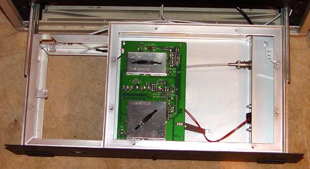
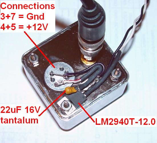
Initially I had planned to install my 5 MHz HSO in the left half of the chassis so the adjusting screw was accessible through the big hole in the front panel, but after hearing what some other people did, I might install it in the right half instead. The coax cable that would connect to the HSO is already in this half of the chassis, as is the raw A+, so all I need is a low-dropout +12V, 1A regulator (LM2940T-12.0 and 22uF, 16V tantalum capacitor) mounted somewhere. I'm sure I can find the space.
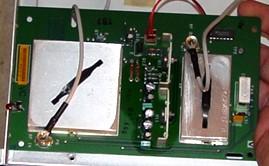
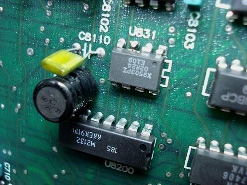
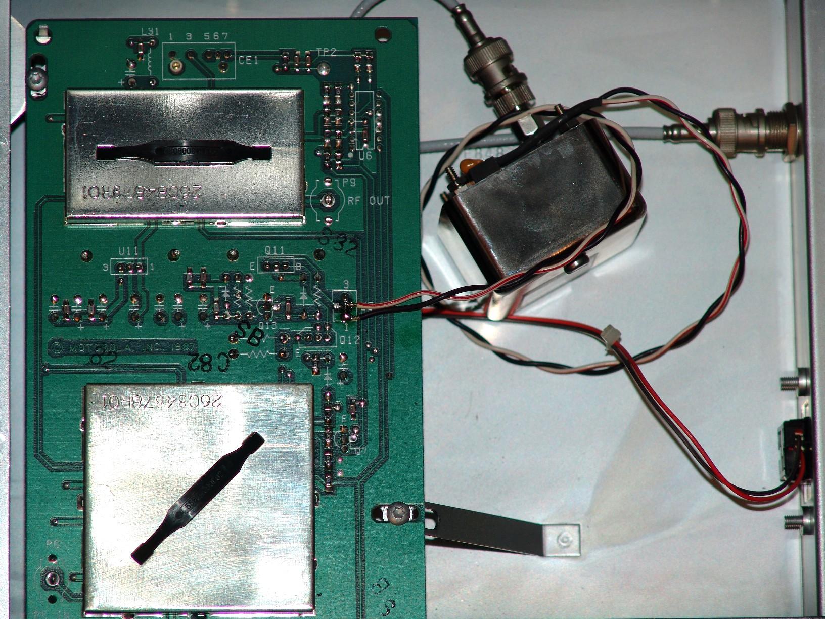
The flip side is shown here. The white object at the far right is the 14.4 MHz channel element / oscillator. The shield to its left covers the buffer amplifier. The coax cable above is the 14.4 MHz RF OUT signal that goes to the RF tray. The power supply regulators and their heat sinks are in the center of the board. Above that is the DC power input plug (red and brown wires). The shield at the left covers the reference oscillator divider circuitry. The coax cable below brings the 5 MHz RF IN signal from the HSO or BNC jack on the side of the station into this board. The Vectron oscillator will be connected to this coax.
Transmit audio disabled:
Some of these stations have had their analog transmit audio path disabled by cutting pin 3 of U831 on the SSCB. This only allows trunking data to modulate the transmitter. U831 is a 50,000 ohm EEPot, Motorola part number 5182335V01. There are about a dozen of these chips soldered into every MSF5000. It is also marked _9312_, which is a Xicor X9312UPI digitally controlled potentiometer, 8-pin DIP, which doesn't seem to be readily available any more. A replacement should be the Intersil X9C503PI, which IS currently available from Digikey. The chip shown below is a Xicor X9503PI, which might be the same as the X9C503PI. (The "I" suffix indicates Industrial temperature range.) Here's a photo taken by Bob W2YMM showing pin 3 of U831 cut right at the chip.
New X9312UP chips were purchased ($5 each, quantity 20) to replace the ones on the SSCB. This is a more permanent repair than trying to solder the lead back on the existing chip. (The ICs arrived 26-Feb-08.)
We didn't pull our stations apart enough to see if any of these chips were cut on the initial checkout.
We worked on the stations 08-Mar-08 and replaced U831 on four of the six stations. This immediately got transmit audio working again: DPL, repeat audio, CW ID, and alarm beeps. We removed the SSCB from the station, cut the pins at the chip body, unsoldered and removed each pin from the board, sucked the solder out of each hole, then installed the new IC and soldered it into place.
Missing hardware:
On the station we opened, several screws were missing. These are used to hold all of the assemblies into the angle-iron frame that forms the chassis. The proper screws are black T30, self-tapping, M6x1x10mm. The current part number is 0312016A54 and they cost $0.17 each from Motorola, less from other sources. Each assembly takes four screws, but two will hold some things in place. The holes were already tapped; the screws were just lost or left out by lazy people who previously worked on these stations. Ordinary steel or stainless steel pan-head Phillips M6x1x10mm screws were purchased at a cost of $8 for a box of 100. Each station was missing 4 screws on average.
Station Programming:
I started by reading the default code plug for System 1&2 stations: CONV.DEF, then back at the Main Menu, choose F4 - CHANGE/VIEW Codeplug data. From that point on, follow the information in the table below. It is important to set up the Station Model/Options information first. You can hit the TAB key to proceed to the next field and/or page, or you can just use PG DN to navigate. Anything not mentioned here assumes its default value.
| Screen or Menu Name | Pg | Field Title | Value | Comments (see note) |
|---|---|---|---|---|
| F8 - Station Model/Options | 1 | Freq Range R1 | 896 MHz | Press F2 to continue |
| 1 | Repeater Operation | Enabled | Allows RX during TX | |
| 2 | SECURE Equipped | Disabled | Press F2 to continue | |
| F6 - Advanced Information | 1 | Auto ID Delay | 001 | |
| 1 | Auto ID Interval | 008 | Won't accept 009 ! | |
| 2 | Channel Control | Station | ||
| 2 | Key Control | Station | ||
| F3 - Mode Information | 1 | RX PL/DPL Code | 311 | |
| 1 | TX PL/DPL Code | 311 | ||
| 1 | PTT Priority | LR | Local and Repeater | |
| 1 | TOT: Line | 000 | ||
| 1 | TOT: Local | 060 | ||
| 1 | TOT: Repeater | 180 | ||
| 1 | Receiver Control | SC | "AND" Squelch | |
| 1 | Repeater Activate | SC | "AND" Squelch | |
| 1 | Repeater Holdin | SC | "AND" Squelch | |
| 2 | Rptr Drop-out Delay | 012 | ||
| F4 - Channel Information | 1 | TX Idle Calculation | Manual | |
| 1 | TX Frequency | 927.45000 | Press F2, then F10 | |
| 1 | RX Frequency | 902.45000 | Press F2, then F10 | |
| 1 | TX Idle Frequency | 927.55000 | Press F2, then F10 | |
| 1 | Call Sign | WA1HRC/R |
After configuring the code plug, press F10 as many times as needed to get back to the Main Menu, then press F3 - GET/SAVE/PROGRAM Codeplug Data.
You can write this System Version 2 code plug to the station now or at a later time. No further conversion is necessary unless you upgrade the station's firmware, which will get you to System Version 3. Motorola recommends that you upgrade your existing System Version 2 code plug rather than starting fresh with CONV_3.DEF. In fact, they also recommend you always start with CONV.DEF and let RSS and the system decide which version to upgrade it to, even if you have a System Version 3.
We programmed four of the six stations on 08-Mar-08 by reading the default code plug I had created earlier and writing it to the station. Worked just fine. Everything went according to plan. After performing an RF alignment, I did have to go into the Service menu, Station Alignments screen, and set the Receiver Squelch and Repeater Squelch EEPots by using the diagnostic metering panel, and set the Transmit Deviation EEPot to 75 just to get us going.
Things We Found Out Upon Initial Inspection:
Dirt, dirt, and more dirt; lots of it. All of the fan trays had labels on them stating the fans had been replaced in 2001. Two of the four screws were missing from most of the DPAs and FPAs, and one to three screws were missing from the RF tray on each station. The reference oscillators still had their "Remove Shipping Bolts" tags on their mounting screws.
We did not slide out any RF trays to unlock the VCOs or check U831 on the SSCB on the first work session, but we did open some stations on the second visit and found three of the six ICs had pin 3 cut. All of the stations had their VCOs locked. New ICs have been ordered and received.
Each station powered up, showed 4.07 for the SSCB firmware version and 5.04 for the TTRC version. No errors were present. The stations went right to channel 1, mode 1 and sat very happily. We did not connect a computer to read the code plug, as it doesn't have much meaning to us. These were all Trunking Repeater stations and will need a completely new conventional code plug in order to be used as an amateur repeater.
Both VCO LOCK LEDs were on, but one system didn't light the RX LOCK LED and the M5 reading for that station was up at 46; typically it should be 36-40. I suspect a slight adjustment will bring it back to operational status.
We measured the transmitter output power. One station had only 60 watts and the PA FULL LED was not lit. All of the others were making 130-145 watts and all of the LEDs lit normally. The initial meter readings are summarized below. See the notes after the table for an explanation of the cells with asterisks (*) in them.
| Initial Meter Readings By Station Number | ||||||||
|---|---|---|---|---|---|---|---|---|
| M# | Description | 1 | 2 | 3 | 4 | 5 | 6 | Typ |
| R1 | Detector | 26 | 22 | 22 | 23 | 23 | 26 | 23 |
| R2 | I-F Level | 22 | 22 | 18 | 20 | 20 | 23 | 20 |
| R3 | Mixer Inj. | 38 | 32 | *0 | *15 | 35 | 33 | 30 |
| R4 | Int. Ref. Osc. | 0 | 0 | 0 | 0 | 0 | 0 | 0 |
| R5 | RX VCO SL | 40 | 39 | 42 | 40 | *46 | 41 | 38 |
| T1 | Final Fwd. | *19 | 29 | 30 | 30 | 30 | 30 | 30 |
| T2 | Final Refl. | 1 | 0 | 0 | -4 | -4 | -1 | 0 |
| T3 | Control | 18 | 18 | 17 | 17 | 17 | 18 | 18 |
| T4 | Driver Fwd. | *24 | 34 | 38 | 35 | 30 | 35 | 30 |
| T5 | TX VCO SL | 40 | 40 | 40 | 40 | 40 | 39 | 40 |
| Pwr | *60 | 130 | 145 | 135 | 135 | 135 | 135 | |
| --- | U831-3 Cut | Y | Y | Y | Y | Y | Y | --- |
Resolutions:
I adjusted the RX VCO about 1/4 turn on station 5 to bring the meter reading from 46 to 38uA. The RX LOCK LED turned on.
I adjusted the mixer injection coils about 1/8 turn on station 4 and that brought the meter reading from 15 to 38uA.
When I turned station 3 on, I got an M3 reading and was in the process of peaking the mixer injection coils, but suddenly M3 went to zero and that was all I could do with it.
I was able to get just over 150 watts on station 1 by adjusting the front panel Power Out pot, but the PA FULL LED still would not come on. I opened the Driver Power Amplifier (DPA) and plugged a meter into J503. Position 3 only measured 2-3uA; it should be over 5uA, so either the first stage of the DPA is bad or the coax or IPA in the RF tray has a problem. Subsequently we pulled the Uniboard but found nothing wrong. We then removed the wrap-around cabinet and put a wattmeter between the IPA and the DPA; it went up to about 1 watt with 60 watts coming out of the station. So the problem seems to be with the IPA, its coax, or the control circuitry running it. We observed the amber PA KEY LED dimly illuminated and the green PA FULL LED was flickering slightly when the station was not transmitting. This is not right.
We spent another hour and a half on 15-Apr-08 working on the last two stations. We replaced the U831 chips, installed the oscillators, programmed the stations, and tried to tune them up. The one that had no M3 reading remained at zero but we managed to peak the receiver front end anyway. The station seemed to be off-frequency, but it could have been the lack of mixer injection signal. The other station - the one making only 60 watts - seems to be rather insensitive and we never got real good meter indications on M2.
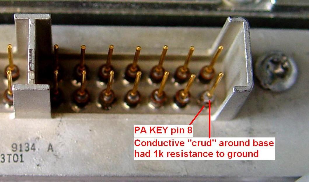
Update: 20-Jun-08. On station #1, I discovered the PA KEY signal coming into the Uniboard was resting at about 5V rather than 8V. I swapped Uniboards; no change. I pulled the interconnect board under the RF tray; I couldn't find anything wrong with it. All resistance measurements on this line matched what I had on a good station. Eventually I pulled the feedthrough connector block out of the RF tray casting. I found several thousand ohms to ground on the PA KEY pin. Apparently this decreased when 9.6V was applied to it. I scraped some kind of chemical growth off the filter that the pin runs through and got the resistance back to infinity, which was what all the other pins had. I put everything back together and the station is now making 150 watts and then some. All the PA LEDs are functioning properly. Only the receiver problems remain. By the way, this entire connector assembly retails for about $250, so I'm glad I was able to fix it. The photo below shows this condition:
Update: 21-Jun-08. On station #3, I had a healthy +25dBm signal coming out of the injection amplifier feeding the mixer coil assembly, so I pulled the front end, removed the mixer coil assembly, opened it up, cleaned inside (didn't really find anything odd), and tuned it up outside the station. The coils were way off but did peak nicely. I put everything back and had 18 on M3. I tuned the three mixer coils and now M3 reads 37. I still have to completely tune the receiver and there are a couple of other issues that are only now showing up, like a forward power alarm and apparently no TX audio.
Update: 25-Jun-08. I was doing final alignment on station #2, which was one that we had difficulty seeing the front-end tuning dips on M2. It turns out that M2 is rather insensitive at the low end (20dB for a change of 2uA on the meter) but it moves a lot more for the same change at the high end (20dB causes a change of 10-14uA) on the meter). So, when aligning the front end, use a lot of signal, just below the point where the meter saturates; this will let you see the tuning dip very easily. I know our initial tuning attempt was made with the meter around 25uA, and on some of the stations M2 idles around 20-24.
Update: 06-Jul-08. Spent two hours doing the final alignments on stations 4, 5, and 6: set the 14.4 MHz oscillator steering line voltage, TX VCO, RX VCO, retuned the receiver, set the IF AGC voltage, Overdrive power cutback, forward and reflected alarm trip points, output power, Repeater and Receiver squelch EEPots, overall transmit deviation EEPot, repeater deviation EEPot, Flutter-Fighter level EEPot. I've been running stations 1, 2, and 3 individually over the past two weeks and they're all doing just fine. I also measured the carrier frequency of one of the stations; using a frequency counter that was adjusted to be within 1 Hz at 10 MHz, it was within 100 Hz after only a few minutes.
Station Tune-up:
After loading in a working amateur-frequency code plug, we performed the following adjustments on the RF tray:
Three EEPots needed adjusting after the stations were reprogrammed; these were accomplished using the computer and RIB. Insufficient test equipment was present to set the deviation properly or do a complete alignment.
Subsequently, after the stations were repaired, a full alignment was performed, setting the forward and reflected alarm trip points, output power, squelch settings, transmit deviation, repeater gain, IF AGC, overdrive, and reference oscillator steering line.
Block Diagrams:
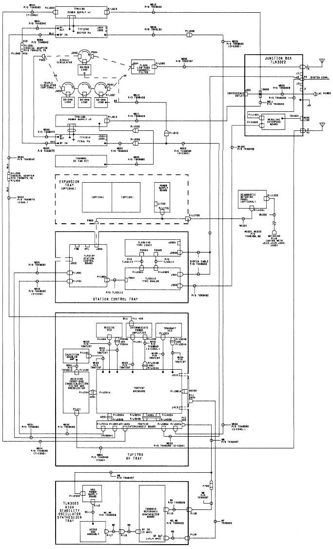
There are two 150w 900 MHz station configurations: plain repeater and trunking repeater. The primary difference is that the trunking repeater requires an external 5 MHz high-stability oscillator signal to lock the reference oscillator, whereas the plain repeater contains an HSO in its reference oscillator chassis. Note that these diagrams are for an ANALOG (CLB) station, but the RF and HSO sections are the same. Here's a station wiring diagram for the plain repeater, which has an internal HSO:
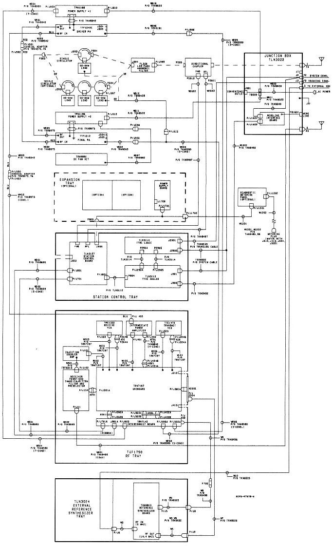
Here's a station wiring diagram for the trunking repeater; these match the stations we all bought from New Jersey and they require a 5 MHz reference oscillator input signal:
Test Equipment:
To test and align these stations, the following pieces of equipment were brought to Jim's garage as needed. All of this weighed a lot less than any single station.
The following were not brought to the first test session, but were used subsequently:
Subsequently, during repair and final tune-up, I also used a Fluke 189 Digital Multi-Meter, an imported deviation meter, and an RF sampling probe.
Performance Tests of the 5 MHz HSO:
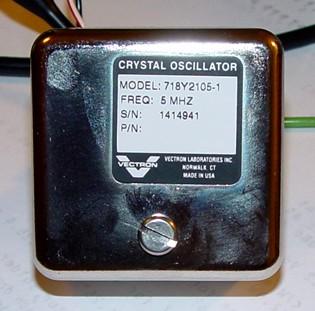
Six Vectron 5 MHz ovenized crystal oscillators were purchased. I connected one to a 12.0VDC supply and a frequency counter, then applied power. Initially the oscillator output was about 125 Hz low and drew 560mA. The frequency rapidly approached 5 MHz and was within 0.05 Hz in only three minutes. The current then started dropping and stabilized around 160mA after a few more minutes. After 30 minutes the current was down to 120mA, the oven was very slightly warm, about body temperature, and the output frequency had stabilized at 4,999,999.993 Hz. The final output frequency of the station is almost 200 times higher, so the actual carrier frequency error is about 1 Hz. That's close enough for anyone, not just the government. Here's a photo of the label side of the oscillators:
And here's the connection side. The wires supply 12.0VDC. The SMA-to-BNC adapter was purchased separately.
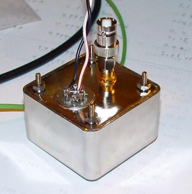
I measured the RF output level at +14.5dBm with absolutely no residual AM or FM present. I also lowered the supply to 11.0VDC and while the input current increased, there was no change in frequency or output level. At 10.5VDC, the output level dropped slightly to +14.3dBm.
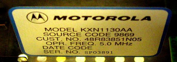
For comparison, a real Motorola HSO in a reference oscillator chassis puts out about +11dBm and runs at approximately 11.4VDC. The entire chassis used 1.2 amps. It took 20 minutes before the heater current started dropping; at that time it was within one Hertz. It took the better part of 45 minutes to fully stabilize, at which time the chassis was drawing 0.6 amps. The stock HSO is much bigger than the ones we purchased from Alltronics, but it strongly resembles other oscillators manufactured by Vectron. Here's a photo of the label on the stock Motorola 5 MHz High Stability Oscillator:
I also fed my signal generator into the HSO input after properly aligning the reference oscillator. My unit will lock up on any frequency between 4,999,894 Hz and 5,000,059 Hz. The stock HSO took almost 3 minutes to reach the lowest frequency for the VCO to lock. The Vectron unit gets to the same point in just 20 seconds. The stock reference oscillator also locked up at 5 MHz with a signal level of -17dBm, so anything higher than that will work just fine. The Vectron units put out just over +14dBm.
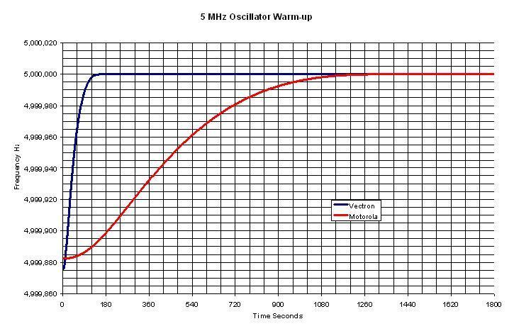
Here's a graph of how the two oscillators warm up. The new Vectron unit is the blue trace. The stock Motorola HSO is the red trace. Each horizontal division represents one minute. The reference oscillator will lock up once the input frequency reaches 4,999,900 Hz, although the station will still be way off frequency.
| Summary of High Stability Oscillator Measurements | ||
|---|---|---|
| Parameter | Vectron | Motorola |
| Frequency at turn-on | 4,999,875 Hz | 4,999,882 Hz |
| Time to reach 4,999,900.0 Hz | 20 seconds | 190 seconds |
| Time to reach 4,999,999.0 Hz | 130 seconds | 1143 seconds |
| Time to reach 4,999,999.9 Hz | 161 seconds | 1300 seconds |
| Time to fully stabilize | 21 minutes | 60 minutes |
| Output Level into 50 ohms | +14.5 dBm | +11.2 dBm |
Powering the Vectron 5 MHz Oscillator:
I assembled an LM2940T-12.0 low-dropout regulator and a 22uF, 16V tantalum capacitor; this value is recommended by the manufacturer's data sheet. I mounted the regulator onto one of the four #4-40 mounting screws of the oscillator. This means the ground terminal of the regulator is attached to the case of the oscillator and it is being used as a heat sink for the regulator. Both will get slightly warm at turn-on, although you'll never feel it. When the HSO draws 0.6A and the station is in receive mode, there's about 15.5VDC on the input of the regulator and 12.0VDC on the output. Power dissipation is 2.1 watts (3.5V times 0.6A), clearly within the operating range of the device. As the HSO will be warming up for a few minutes, this extra heat may also help it come up to operating frequency sooner. The current starts dropping off within three minutes anyway, settling down to about 0.14A. At this point the regulator is only dissipating 0.5 watts. Here's a photo of the completed HSO assembly:
I varied the input voltage to the regulator. On the one I tested, I could get down to 12.45V when the oscillator was cold, even lower (12.25V) when the oscillator was warmed up, and it would still provide 12.03V out. This voltage is considerably lower than the raw A+ supply would ever be, even when the station is transmitting. The HSO will operate fine down to just below 11.0V, and if the raw A+ gets that low, you've got other problems.
I subsequently built up the remaining five oscillators, let each one run for 30 minutes with 15.0VDC input, then adjusted them to be within 0.01 Hz at 5 MHz. As they came from the supplier, only one of the six units was off by more than 1 Hz.
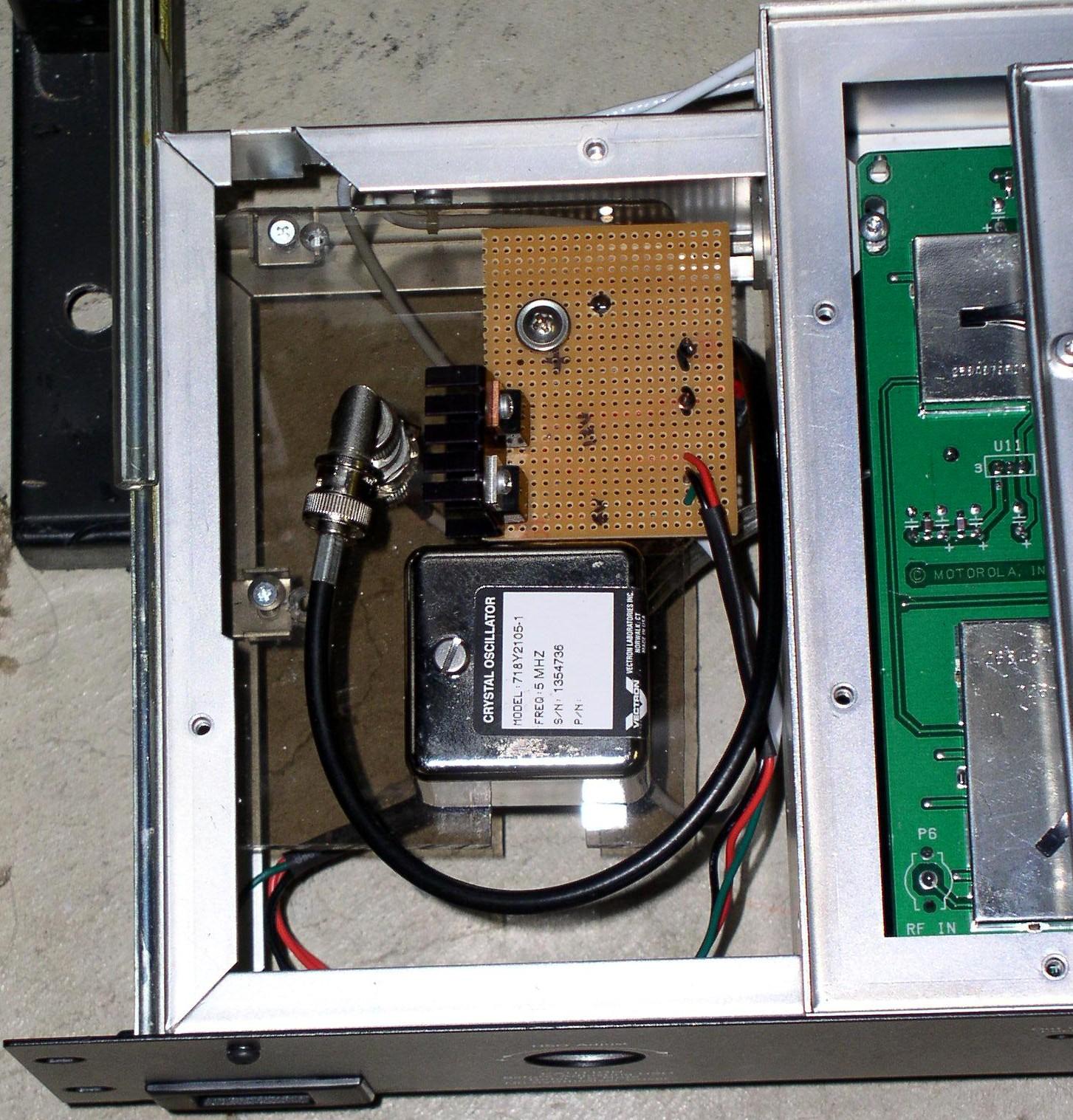
On 09-Apr-08 (after a long hiatus), Jim N1GTL (with my help) installed new HSOs into the four working stations. The 250V 1A fuse under the right side of the reference oscillator tray was replaced with a 250V 1.6A fuse to allow for the new HSO. The DC power leads of the HSO assembly were soldered directly to the DC power connector terminals on the back of the reference oscillator circuit board inside the tray. The 5 MHz input BNC connector was removed from the bulkhead connector (under the circuit board) going to the station junction panel, and attached to the BNC jack on the HSO. We used a two-inch piece of double-sided foam tape to hold the HSO to the bottom of the tray, in such a position that the adjusting screw can be removed and the trim pot can be accessed. Here's a photo taken by Jim N1GTL of a working HSO connected and mounted in the reference oscillator chassis:
The stations were powered up and the Unlocked LED on the front of the reference oscillator tray stayed lit for about 20-30 seconds as the HSO warmed up. During this time the two VCO LOCK LEDs on the SSCB were not lit and the station displayed a few VCO-related errors. Once the HSO frequency got within range, the Unlocked LED turned off, the two VCO LOCK LEDs turned on, and all the error codes disappeared. After three minutes - the time it takes these HSOs to reach their final operating frequency - the stations operated as expected with no additional (external) equipment attached. We also read the existing code plugs, made a couple of minor changes, and wrote them back out.
Mark N9WYS mounted his HSO and power supply components on a piece of plastic in the left half of the reference oscillator chassis and made a suitable coaxial cable to bring the 5 MHz signal into the other half of the chassis. He built up +12V and +5V supplies; I felt that only a +12V low-dropout supply was necessary. Here's a photo of his installation:
Manuals And Other Documentation:
Most of these are, naturally, No Longer Available (NLA) from Motorola.
MSF5000 Digital-Capable and Analog-Plus Instruction Manual: 6881092E05.
MSF5000 900 MHz Digital-Capable and Analog-Plus Service Manual: 6881092E90.
MSF5000 Trunked Repeater and Repeater (RT) Stations (896-902 MHz Receive, 935-941 MHz Transmit) Instruction Manual: 6881064E70. Analog station.
PURC5000 UHF Paging Transmitter Service Manual, 6881077E35: Analog station.
Documentation for the Vectron 5 MHz oscillator was obtained from Alltronics web site. I sent an inquiry to Vectron for more information; I never got a reply.
Acknowledgements and Credits:
A big round of thanks to Jason WA1NH and Scott N1SEC for making the day-long trip through New England to New Jersey, picking up about 27 stations, and delivering them on the way back.
Thanks go to Dave N1OFJ and Jim N1GTL for going along with me to purchase six stations for the New Haven CT area. Big thanks to Jim for letting us store them and work on them in his heated garage.
Thanks to Mark N9WYS for scanning the manual section for the reference oscillator chassis and showing me an alternative mounting suggestion for the HSO.
All photographs were taken by the author except where otherwise noted. Thanks go to Jim N1GTL, Bob W2YMM, and Mark N9WYS for supplying additional photos.
MSF5000, PURC5000, RSS, and a whole bunch of other terms are trademarks of Motorola, Inc.
The Vectron 5 MHz oscillators were purchased from Alltronics of Morgan Hill, CA. Their part number is 04P010. These were No Longer Available when I checked in March 2009. 10 MHz oscillators may be used if jumpers are changed on the HSO circuit board. Consult the relevant manual section elsewhere in the MSF area for jumper settings.
Contact Information:
The author can be contacted at: his-callsign [ at ] comcast [ dot ] net.
Up one level (MSF index)
Up two levels (Moto index)
Back to Home
This article first posted 11-Apr-2008
This web page, this web site, the information presented in and on its pages and in these modifications and conversions is © Copyrighted 1995 and (date of last update) by Kevin Custer W3KKC and multiple originating authors. All Rights Reserved, including that of paper and web publication elsewhere.