Motorola index
Back to Home
of an MSF5000 Station
By Robert W. Meister WA1MIK

|
MSF index Motorola index Back to Home |
DTMF On/Off Control of an MSF5000 Station By Robert W. Meister WA1MIK |
|
This project was written up out of necessity - the mother of invention (I bet that's a copyrighted phrase somewhere on the planet).
Background:
The New Jersey 896 MHz MSF5000 repeater stations can be programmed and used on the amateur 902-928 MHz band. The built-in CW ID and timers can be set appropriate for the amateur service. The only thing these stations lack is a simple means of legal on/off control; I prefer that it can be performed over-the-air.
DTMF is one of the simpler methods to use and is preferred since most of the radios used on the 902 MHz band either have DTMF built-in or can be equipped with a DTMF microphone.
Since the FCC's amateur rules and regulations now permit over-the-air control on frequencies below 220 MHz (at one time that was the lower limit), there's no reason this same technique couldn't be used on any band for which an MSF5000 station exists. Also, while I only had digital-capable stations available to me, this configuration should also work - with different signal tap-off points - on an analog (CLB) station.
What I Wanted/Needed:
I didn't need a complete repeater controller with CW ID, timers, courtesy tones, voice, etc; the MSF5000 already has most of that. I didn't have the luxury of connecting the MSF5000 to another repeater's controller since there may not be any at some sites. I just wanted a simple DTMF decoder that would be an inexpensive add-on to these otherwise fine machines. I didn't want to modify the MSF5000 if possible.
I reduced my requirements to a single-function, multi-digit, DTMF decoder that could operate with the existing signals present in the MSF5000 station. I found such a unit for $46US (plus $7.50 s&h) at www.dschmidt.com; look for "DTMF Activated Relay, selectable codes and relay modes". The product model is DTMFRLYB-T. It operates from 7.5 to over 20VDC and draws about 100mA when the relay is activated.
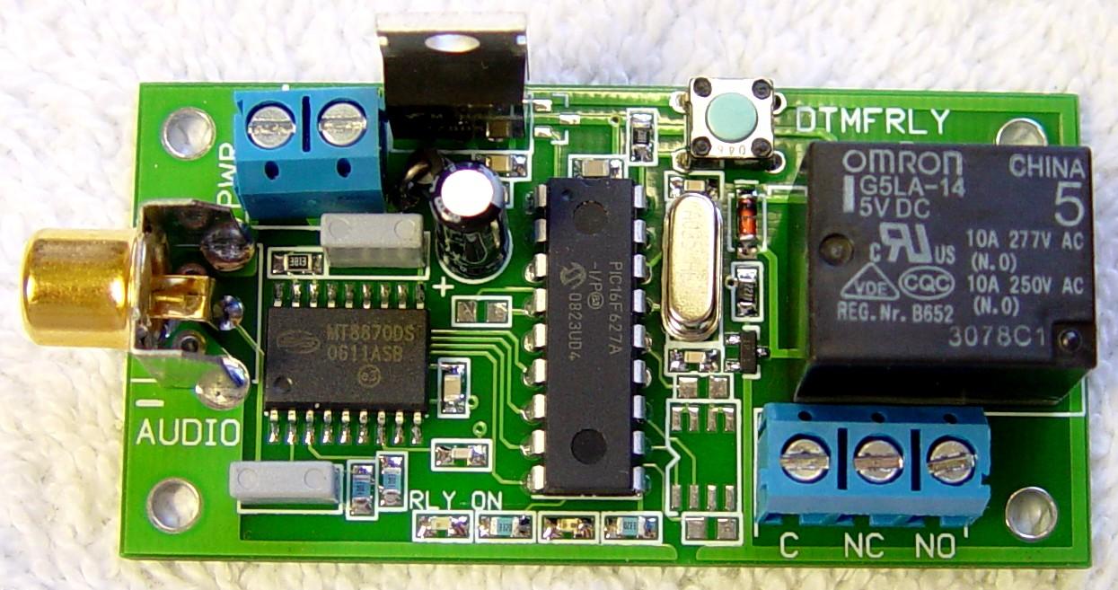
The unit is 2.75 inches long by 1.5 inches high by 0.8 inches tall. It uses a gold-plated RCA jack for audio input and Euro-style terminal strips for power and relay contacts. Four 1/8-inch diameter holes in the corners allow flexible mounting opportunities, or you can use one #4-40 screw through the LM7805 regulator to attach it to a grounded panel.
UPDATE May 2011: The DTMFRLYB product has been slightly redesigned to use smaller parts and is now $48US. It can be ordered with either an RCA jack or a Euro-style terminal strip for the audio input. The model numbers are DTMFRLYB-C-R (RCA jack) or DTMFRLYB-C-T (Terminal strip).
There is no facility with this decoder to mute the received DTMF signals. They will be heard coming through the repeater as you send them. I do not wish to imply that muting is not possible; it's just not provided on the DTMFRLYB and I didn't go looking around in the station for an appropriate mute input. My needs did not include security, just a legal means of turning the repeater on and off to meet FCC part 97 rules.
Testing The Decoder:
I could have just connected the decoder to a station and discovered the hard way that it didn't work the way I expected, but I don't do things that way. I did some bench-testing first. I connected an old telephone company DTMF pad to a 9V battery using one resistor and one capacitor. This gave me a nice 0.8VRMS signal, which I used to program the decoder to close the relay when an asterisk was heard and open the relay when a pound sign was heard. I ran some tests to check decode time and overall sensitivity; it met the published specifications. The unit uses an industry-standard MT8870 DTMF decoder chip with recommended component values.
I then fed the DTMF signal into my RF signal generator as external AC modulation and fed the sig gen into my deviation meter. I came up with a calibration chart that allowed me to set the deviation control on the sig gen to some value and have a known deviation come out of it. (The deviation control value is only accurate when the internal modulation source is used.) I then fed the sig gen into a MaxTrac UHF receiver (it was the first one I grabbed) and fed the headset audio from the radio into the DTMF decoder to test its ability to properly decode digits in the presence of noise.
I found that the unit would reliably decode (without falsing or chattering) DTMF modulation as low as 1 kHz deviation (on a 5 kHz wide receiver) with an RF signal at 20dB quieting. With weaker signals, the crackles caused the DTMF decoder to drop out and decode the signal multiple times. This means that if your control string has several digits with the same value in a row (i.e. 12223), the repeated digits could all be decoded with a noisy signal (i.e. 123). The user is therefore cautioned to make sure each digit differs from the ones on each side of it. With a stronger, quieter signal, less deviation was necessary to get proper decoding. I found I could go down below 0.4 kHz of deviation and still get reliable decoding. At such a low level of deviation (under 10%), the limiting factor is the input sensitivity of the DTMF decoder chip: 25-30mV. Depending on the audio level feeding the decoder, you can tailor your minimum deviation acceptance parameters.
Connecting to the MSF5000:
There are several ways that this DTMF decoder can be connected to the MSF5000 station. The stock New Jersey stations came with the Trunked Tone Remote Control (TTRC) boards and wiring. Some people may have removed these due to programming issues or because they felt they would never be needed. Others may have used them with an external repeater controller. Well here's one reason to leave it in: the board supports an input signal called TX INHIBIT that makes simple control easily possible. Ground this line and the transmitter shuts off. Unfortunately there's no source of power for the DTMF decoder on the J2 connector on the side of the station.
You can also utilize some signals on test points on the Secure-capable Station Control Board (SSCB), but finding some place to disable the transmitter requires removal of the SSCB and attaching a wire to a transistor underneath. There are several board layouts; you would need the proper component position diagram from a manual that matches the board you have to locate the correct spot.
The expansion jack on top of the control tray has some of the signals as well, but as that connector is also used for metering, you would either have to make a special cable to allow you to pick up the signals for the DTMF controller plus the metering cable, or do without control while using the metering panel. It's probably more expensive than any of the other methods.
Someone mentioned using the front panel ACCess DISable switch, and this is a really good idea. The center terminal of that switch already goes to ground, so shorting the proper lead to ground will definitely turn off the transmitter, as well as light up the DIS LED on the front of the station. This switch is present on ALL MSF5000s (analog, digital, analog-plus) so positive control is available with or without a remote control board.
The DTMF decoder can be mounted under the plastic control tray using some double-sided foam tape, to the SSCB or the top of the RF tray, or it can be mounted inside the station cabinet near the junction panel. You could even mount it outside the station and use a DB25 connector to plug into J2 on the junction panel, however this leaves the station open to security breaches as someone could easily unplug the DTMF decoder and walk off with it.
I'll try to discuss some of the possibilities that I came up with. You may have other ideas depending on your requirements and skill set. A lot of information came from the MSF5000 Interfacing and RSS programming articles, found elsewhere on this web site.
Pros and Cons:
Rather than tell you one way of connecting things, I'm going to run through some of the choices and options so you can decide which method, or combinations of methods, is optimal for your situation.
Method: Use the System Option connector (J2) on the station junction panel.
Pros: Least modification required (power). Standard DB25M connector. Easy to install.
Cons: Easy to disconnect. Requires the TTRC and cables. Assumes no other use of J2
(unless you manufacture a Y-cable). Mod needed to the TTRC to get power to J2. DTMF decoder
would need to be encased and mounted externally.
Method: Use the System Option connector (J2) but move it inside the station.
Pros: Least modification required. Standard DB25M connector. Easy to install. Secure.
Can pick up power anywhere inside the station. DTMF decoder can be mounted internally.
Cons: Requires the TTRC and cables. Assumes no other use of J2, as it's now inside
the cabinet.
Method: Connect directly to points on the TTRC board.
Pros: Secure, as it's mounted inside the control tray. Allows existing use of J2.
Cons: Harder to remove: soldered to test points. Requires the TTRC.
Method: Connect directly to points on the SSCB board.
Pros: Secure, as it's mounted inside the control tray. Doesn't require the TTRC.
Cons: Harder to remove: soldered to test points. May require soldering a wire to the
underside of the board.
Method: Use the Expansion Jack on top of the control (or expansion) tray.
Pros: Easy to get to. Has A+ available.
Cons: Doesn't have TX INH signal. Also used by the metering panels and/or station
programming. Cables can be expensive to make.
Connection Points:
Easily accessible connection points in the 896 MHz MSF5000 station are listed below.
| Signal | SSCB | TTRC [1] | J2 | Exp Jack |
|---|---|---|---|---|
| A+ | - - - | J2900-7 [2] | 22 [2] | 1,2,3,4,5 |
| +9.6V | TP5 | TP7 | - - - | - - - |
| Ground | TP2 | J2900-3 | 19 | 21 |
| TX INH | [3] | J2900-4 | 5 | - - - |
| Audio Hi | TP1 | TP2 or 11 | 2 | 39 |
| Audio Lo | TP7 or 11 | TP10 | 3 | 40 |
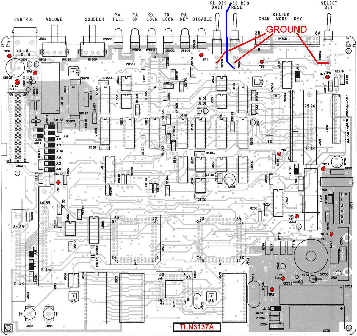
The SSCB (TLN3137A) test points are marked in red in the following pictorial diagram.
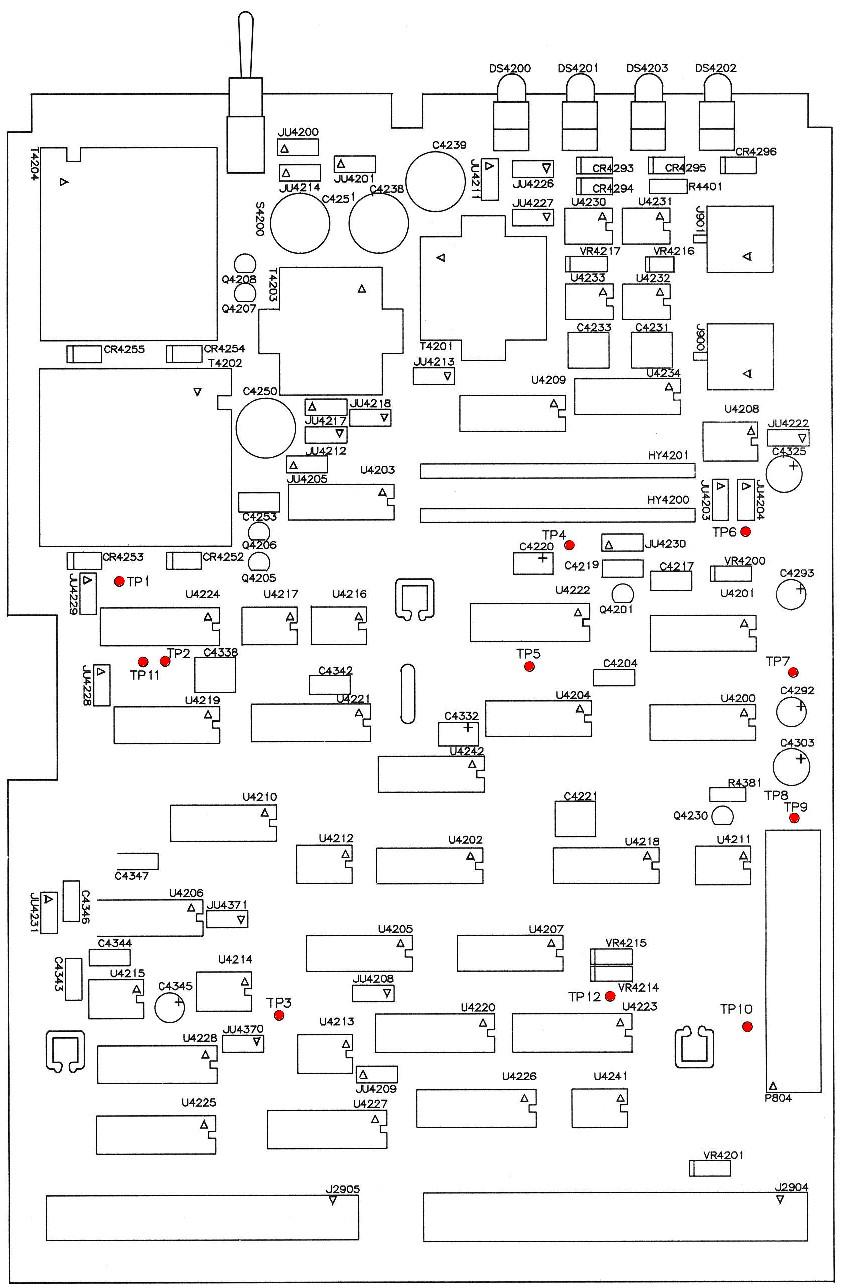
The TTRC analog board (TLN3112A) test points are marked in red in the image below.
If you want to connect this decoder to an analog station, the following untested test points on the Station Control Module are suggested; there are matching points on the digital-capable stations. Consult the rest of the article for details.
| Signal | Analog SCM |
|---|---|
| A+ | - - - |
| +9.6V | TP14 or +9.6V |
| Ground | TP13 or L.G. |
| TX INH | ACCess DISable switch |
| Audio Hi | TP1 |
| Audio Lo | TP15 or 16 or A.G. |
Signal Specifics:
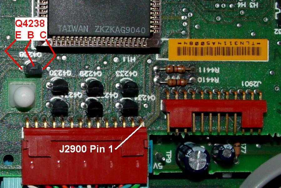
The signal on J2 pin 22 is called RF Relay Control. It provides switched A+ under some condition (which I have not found in the available documentation). To get voltage there all the time, the TTRC logic board must be modified to feed A+ to J2900 pin 7 by adding a jumper across Q4238 from emitter to collector. There are two styles of TTRC logic board: the older one (TLN3112A) has the three main ICs in sockets and uses permanently attached flat cables going to the TTRC audio board; the newer one (TRN7754A) has the three main ICs soldered to the board and has removable flat cables going to the TTRC audio board. Here's the TLN3112 logic board with Q4238 indicated:
And here's the TRN7754 logic board with Q4238 indicated:
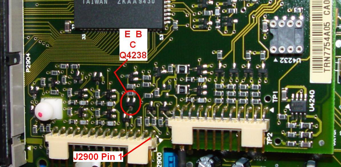
A wire can be added under the TLN3112 board to connect all three leads of the transistor together. A wire can be tacked onto the top of the TRN7754 board to connect all three leads of the transistor together. Static electricity procedures apply; there are sensitive CMOS components on the boards in the control tray.
+9.6V is developed in the RF tray and is available on the SSCB at TP5. This is fed to the TTRC where it appears on TP7 on the audio board. As the DTMF decoder will operate on any voltage between 7.5 and 20 volts, you can use either +9.6 or A+ as your supply voltage.
There are several different grounds in an MSF5000 system: logic ground, digital ground, and analog ground. These are all connected together at one central point and you should not mix them. The audio signals reference analog ground. The dry contacts of the DTMF decoder should go to logic or digital ground. As with the +9.6V signal, there are test points on the SSCB (TP2) and the TTRC audio board (TP8) for the DC and logic ground. You can also pick up logic ground on the center terminal of any of the three toggle switches on the front of the SSCB. Two of these are very close to other test points for audio and power.
The signal that disables the transmitter is called TX INHIBIT (TX INH) and grounding it immediately shuts the transmitter off. You could connect a CW key to this line and send CW with the station; its response is immediate and it completely disables the RF output. The TTRC accepts this input line and causes it to operate the appropriate MUXbus bit, which is sensed by the SSCB and shuts the transmitter off. If you had an expansion chassis and wildcard board on your station, you could configure it to activate this same TX INH bit and shut the transmitter off.
One way to disable the transmitter on the SSCB (i.e. without a TTRC or the TX INH signal) is to inhibit the PA KEY line from leaving the SSCB and activating the transmitter circuits in the RF Tray. The PA KEY line is active low, which causes the transmitter to turn on. To inhibit it, you need to prevent this line from going low, which is done through Q806 on the SSCB. By grounding the base of this NPN transistor, you will prevent it from pulling PA KEY low and thus preventing the transmitter from turning on. Q806 is located on the solder side of the SSCB; there's no way to access it from the component side. This is the reason you need to pull the SSCB out of the station. The effect will be the same as grounding the TX INH line: the transmitter will stop transmitting, however the SSCB may consider this to be an error condition, as it still may expect RF to come out.
Another way to disable the transmitter is to activate the ACCess DISable switch on the control board. This switch is present on ALL MSF5000 stations. The center terminal is ground. Grounding one side (closest to the front panel) resets the station while grounding the other side (furthest from the front panel) disables the station. This line can be held at ground during a reboot with no ill effects. A big advantage of using the ACCess DISable switch is that the red Disable LED lights up whenever the station is disabled. A quick look at the front panel will let you know that the station has been commanded off if the LED is ON but the DIS switch is OFF (in the middle).
The audio signal needed by the DTMF decoder can be as low as 30mV or as high as several volts. If you have a TTRC present, the easiest place to get receiver audio is from the Line 2 signal, a transformer-isolated 600-ohm line-level audio output. This also appears on the L1/L2 terminal strip on the station junction panel, but it's just as easy to get from J2. You will need to set the Line Output Level EEPot in the station (pot #C) to some reasonable value (i.e. 50) to get sufficient audio out of the Line 2 terminals. As this audio signal is floating (i.e. not referenced to ground), you need two wires to use it. The polarity is unimportant; either L2+ or L2- can be grounded at the DTMF decoder. Of course, if you have external equipment connected to Line 2, you may not be able to change the level or ground either side.
Another source for audio is TP1 on the SSCB (Select Audio Sum) or TP11 or TP2 on the TTRC audio board. You would also need an analog ground wire to complete the circuit; that's available at TP7 or TP11 on the SSCB or at TP10 on the TTRC audio board. These test points should be well marked, but not all boards actually have physical terminals installed in the circuit boards at these points, so you may have to solder your wires directly into the holes provided. Some boards have small loops that protrude up from the board; others are just single-pin, push-on terminals. The audio here is de-emphasized, processed by the HearClear circuitry, and muted until a valid coded signal is received. The level is around 900mV for a 400 Hz tone sent at 1 kHz deviation.
The Connections I Chose:
You can mix and match signal sources, taking those that are most convenient and least obtrusive wherever you can. It seemed easiest for me to put the DTMF decoder under the control tray, affixing it with a couple of pieces of double-sided foam tape to the top cover of the RF tray. I completely covered the bottom of the decoder circuit board with a small piece of cardboard to fully insulate it from the grounded cover of the RF tray. Take care where you position the decoder so it doesn't interfere with anything in the control tray when you close it back up. Mounting the decoder here makes it fairly easy to get to if you have to reprogram it and no one will even know its inside the station.
I wired the DTMF decoder to my station using half of a pre-made RCA-to-RCA audio cable for the audio input and two pieces of one-pair shielded audio cable: one for the power and ground, the other for the TX INH signal. The shields were connected to the ground connection at the DTMF decoder board.
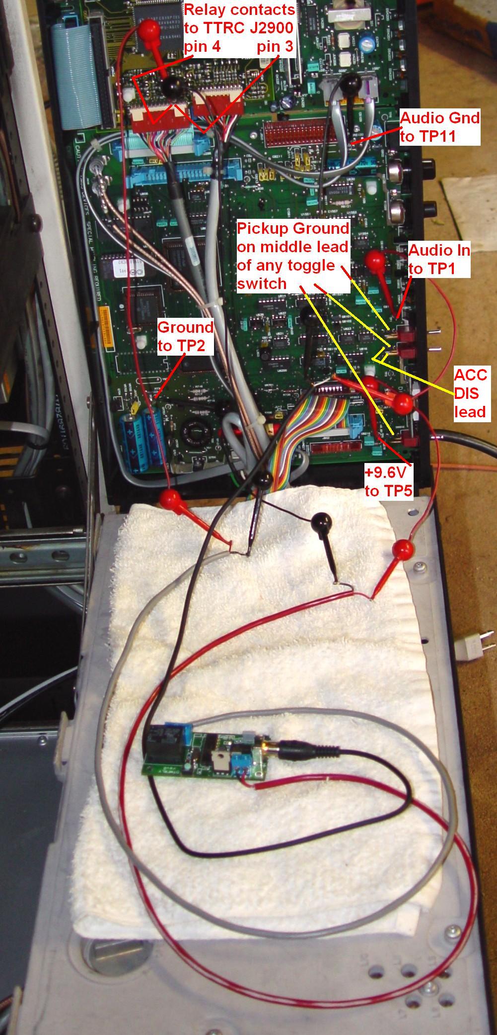
The photo below shows the proof-of-concept connections using clip-leads. As the ultimate destination of this DTMF decoder is someone else's repeater, I did not mount it in my station nor make permanent connections. Also, I made my ground connections to the available test points rather than to the grounded center terminal of the toggle switches. The switches are closer to TP1 and TP5 and I'd strongly recommend using them.
I programmed the DTMF decoder for a multi-digit sequence, connected it with clip leads, and tested it on one of my 896 MHz MSF5000 repeaters using a 900 MHz GTX portable radio to send DTMF digits. Naturally it worked perfectly. As soon as the last digit of the sequence is released, the repeater transmitter either immediately shut off or immediately turned on. I performed this test while listening to the repeater output (i.e. full-duplex) so I could hear what was going on. I also tested it by standing in front of the repeater and observing the LEDs on the DTMF decoder and the front of the station.
After getting the above configuration operational, Jim N1GTL mentioned using the front panel ACCess DISable switch, and I thought it was an excellent idea, enough to get me to re-think using that instead of the TTRC. The switch leads are easy to get to. ACC DIS is the lead that's most accessible and solders into the board furthest away from the switch. I've pointed it out in the photo above. It's also marked with a blue line on the SSCB image further up. Also marked are the center leads of all three switches that are very conveniently grounded. This limits all the connections to just the SSCB.
The Results:
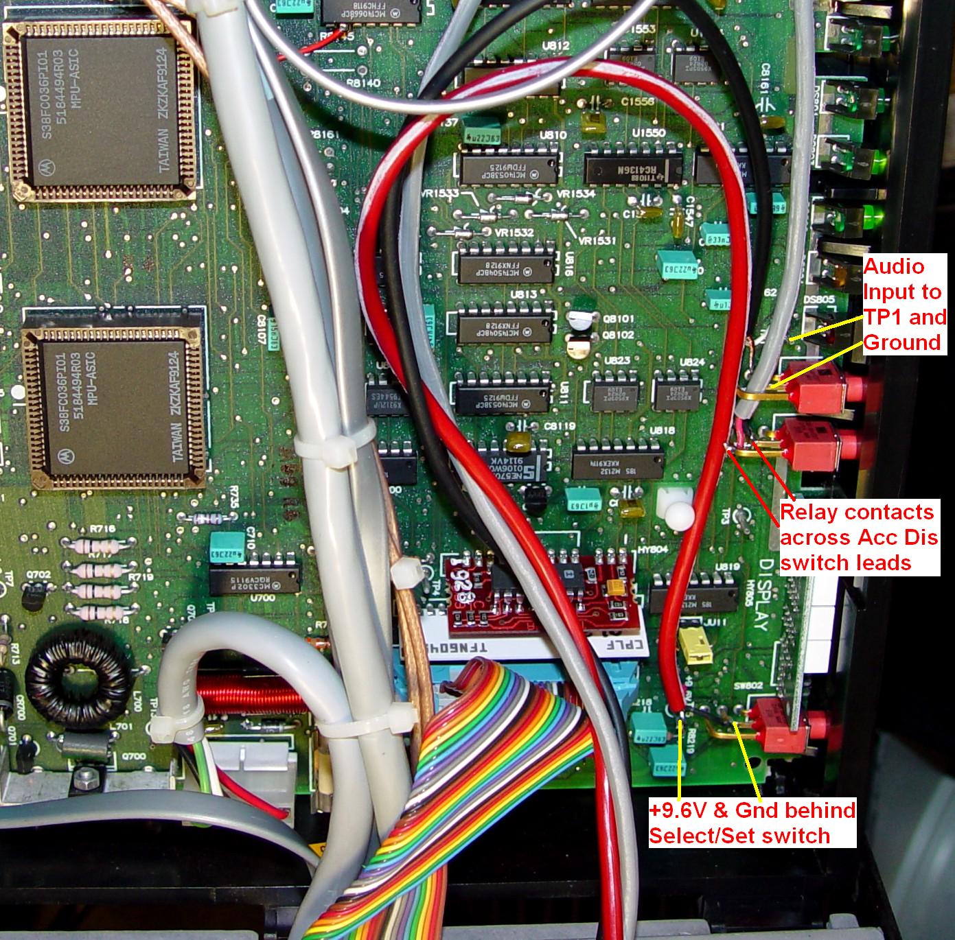
The final connections I used are shown in the annotated photo below. 9.6V at TP5 for power, TP1 for audio, relay contacts across the ACC DIS switch, and grounds to the center leads of the nearest front panel toggle switches.
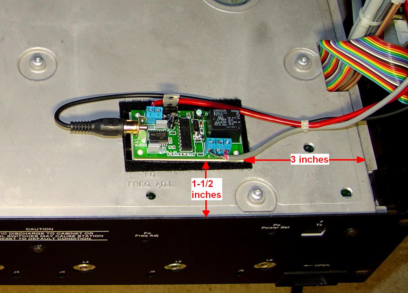
I mounted the DTMF controller on top of the RF tray about 1-1/2 inches behind the front panel and about 3 inches from the right edge of the top cover. I closed the control tray several times to make sure there was no interference. I used several materials to insulate and mount the circuit board. From the top, they are oriented as follows:
The cardboard serves to insulate the controller from any possibility of shorting out to the metal RF Tray cover. The hook-and-loop fastening tape lets me detach the controller if that ever becomes necessary, such as if I need to remove the RF Tray cover. The photo below shows the final installation.
As a hidden bonus, the red "digit detected" LED on the DTMF controller shines through one of the three front-panel holes reserved for the Secure circuit board, so you can see if or when digits are being received.
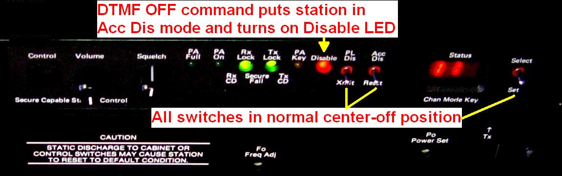
I commanded the DTMF controller to turn its relay ON, thereby disabling the station. In the photo below, the red Disable LED is on as a result. All of the toggle switches are in their normal center-off position. The station has been disabled because the DTMF controller told it to shut off.
Acknowledgements and Credits:
MSF5000 information came from several service manuals, from physical measurements and examination of several stations, and from other MSF5000 articles.
The DTMF decoder was purchased at www.dschmidt.com. The documentation was due to be improved based on comments I sent back to Don Schmidt after testing my unit.
I'll gladly give credit to Jim N1GTL for suggesting the front panel ACCess DISable switch idea.
All photographs were taken by the author unless otherwise noted.
Contact Information:
The author can be contacted at: his-callsign [ at ] comcast [ dot ] net.
Back to the top of the page
Up one level (MSF index)
Up two levels (Motorola index)
Back to Home
This page originally posted on Sunday 08-Mar-2009
Article text, artistic layout, all photographs, and hand-coded HTML © Copyright 2009 by Robert W. Meister WA1MIK.
This web page, this web site, the information presented in and on its pages and in these modifications and conversions is © Copyrighted 1995 and (date of last update) by Kevin Custer W3KKC and multiple originating authors. All Rights Reserved, including that of paper and web publication elsewhere.