Motorola index
Back to Home
MSF5000 Control Tray
By Robert W. Meister WA1MIK

|
MSF index Motorola index Back to Home |
Extracting Boards from the MSF5000 Control Tray By Robert W. Meister WA1MIK |
|
There may come a time when you need to extract or physically remove the SSCB or TTRC boards from the plastic control tray. There are several tricks involved. All the important parts are old plastic that is fragile and will break if mistreated. New parts are No Longer Available, so you don't want to force anything.
It's easiest to work on the control tray by completely removing it from the station. All of the photos of the control tray were done with it sitting on the table all by itself.
While this article discusses the SSCB, the same procedure applies if you want to remove the TTRC modules.
Click on any of the outlined photos or images for a larger view.
Removing the Control Tray:
Remove any screws holding the RF Tray to the chassis. Slide the RF Tray all the way out of the cabinet. Raise the control tray to its service position.
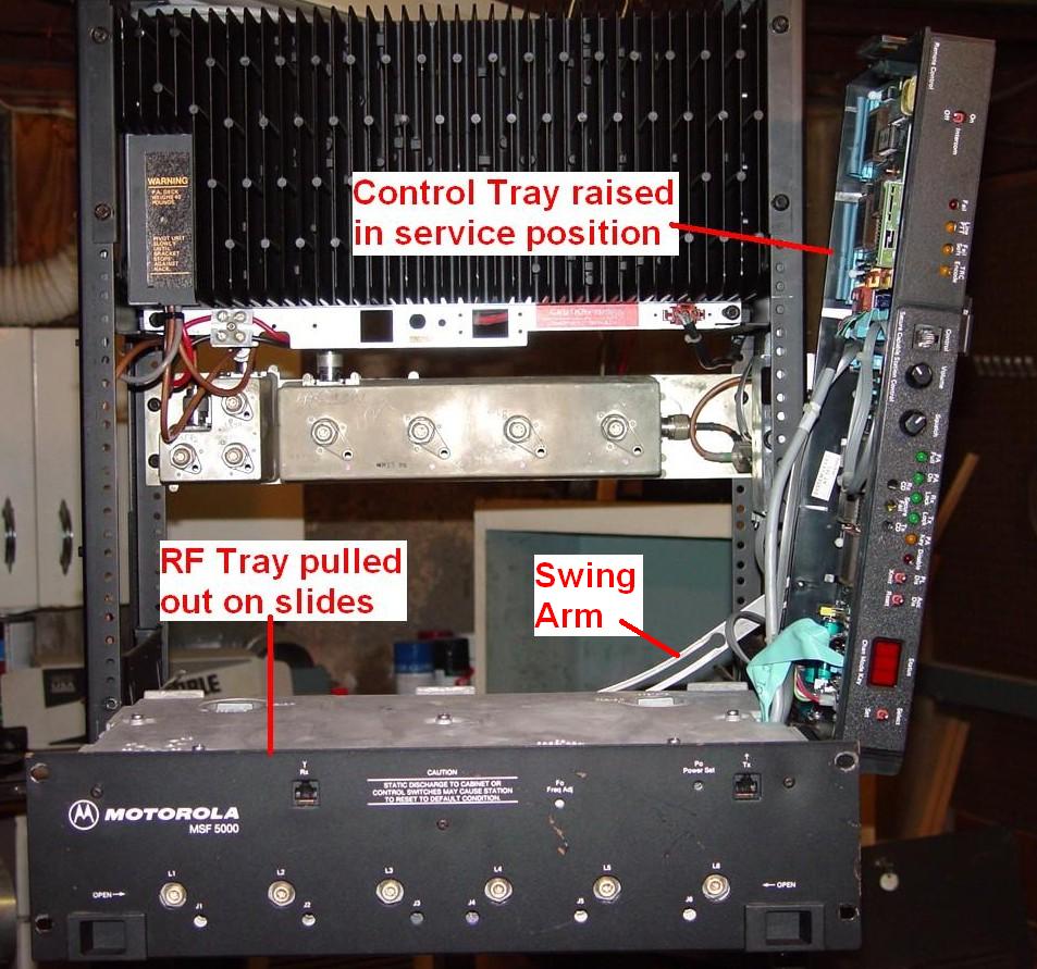
Unplug all the cables from all of the boards. Some SSCBs have two small coax cables with right-angle RCA plugs on them; these will be real tight and you may need a pair of pliers to twist them as you pull them out. The jacks are labeled "F" and "R" but I don't think the cables are, so you should label them yourself. The TTRC also has two unlabeled modular connectors plugged into it; you should label one jack and one plug yourself. All the other connectors are unique and will only plug into the correct receptacle.
There's a metal swing arm at the rear of the control tray that must be disconnected from the post embedded in the control tray.
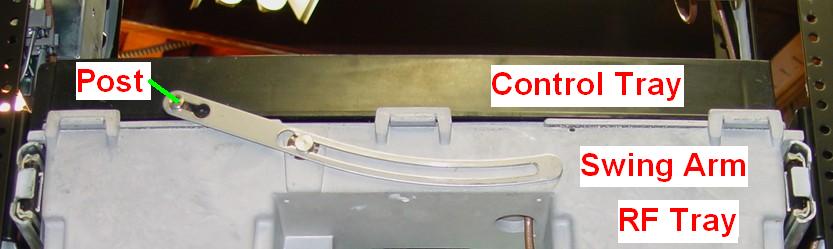
The arm itself has a keyhole slot at the control tray end and a flat metal spring keeps the arm in position in the smaller hole (Hole 1). The post has multiple diameters to fit the swing arm. You can't see these in the photo so here's a diagram of the post and swing arm.
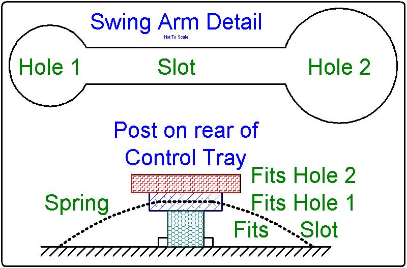
If you squeeze the arm against the spring (that you can't see) towards the plastic tray, you can then lower the control tray a bit so the post fits into the slot. You may have to hold the swing arm while you lower the control tray. Slide it so the post fits into the larger hole (Hole 2) and the swing arm can be disconnected from the control tray. The spring will try to push the post through the larger hole.
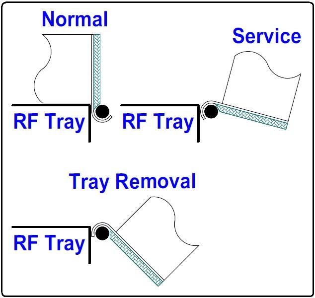
Once the swing arm has been released, CAREFULLY rotate the control tray to the right about 3/4 of the way open (towards 2 o'clock) and it can be lifted and unhinged from the RF Tray. The hinge pieces are VERY FRAGILE and you may break one in the process, especially if you fold the control tray too far towards the right. They're shaped more like hooks. Note that the slot openings are at a 45 degree angle towards the right; don't rotate the tray more than necessary or until those slots are vertical and you can lift the tray off the hinge pins in the RF Tray.
The drawing below shows the hinge area of the control tray in the normal, service, and removal positions. Note how the angled slot opening faces straight down in the removal position. Don't swing the control tray further than this or you risk breaking the hinge pieces. When you hear it go SNAP, CRACK, or POP, you've gone too far!
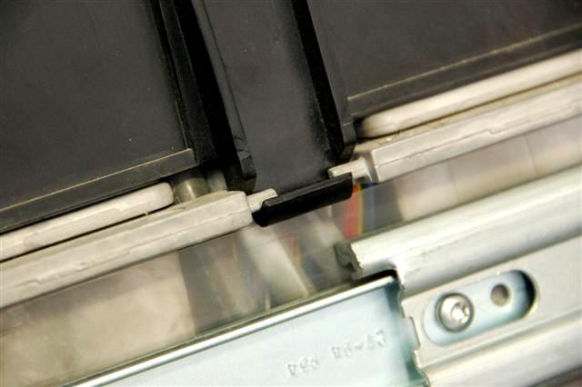
The hinge pins on the RF Tray may be one solid round rod or two shorter pieces with an opening in the middle, as shown below. In this photo supplied by Bob VE3DJ, the control tray is in its normal operating position but you can see how the slot is angled.
It would be a good idea to lubricate the swing arm, especially the springs on the posts. There's a similar post on the back of the RF Tray. There's no need to remove the swing arm from the RF Tray unless you want to clean any rust or corrosion off it.
Removing the Circuit Board:
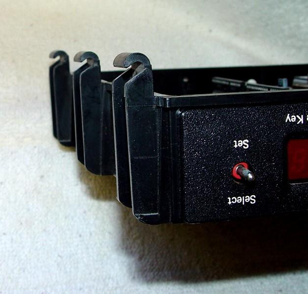
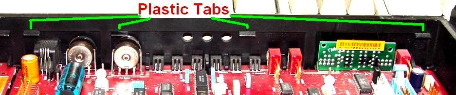
To get the board out of the control tray, you have to remove the appropriate escutcheon or front panel. They are held into the control tray with plastic clips around the top and bottom of the panel. TOP here means the component side of the boards, the side facing you. You have to carefully depress the clips at the top of the panel slightly while pushing that edge of the panel out through the front of the control tray.
Rotate the tray so the front panel is away from you and slowly and gently press down and out on two of the top clips with your thumbs and try to rotate them outward. These clips may break (the whole plastic control tray is a horrible design) but just push them down slightly as you push the panel out the front until the entire top edge is free.
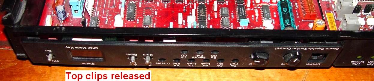
Eventually it will come off and you can easily remove the panel from the control tray. Believe it or not, that's all that holds the board into the control tray.
Now rotate the tray so the front panel is closest to you. Slide the board forward about 1/8 inch or as far as it will go against the plastic stiffeners at the front of the control tray, to clear some hold down nibs inside the rear edge of the control tray.

Lift the rear edge of the board up and pull it out, sliding it backwards as you do.
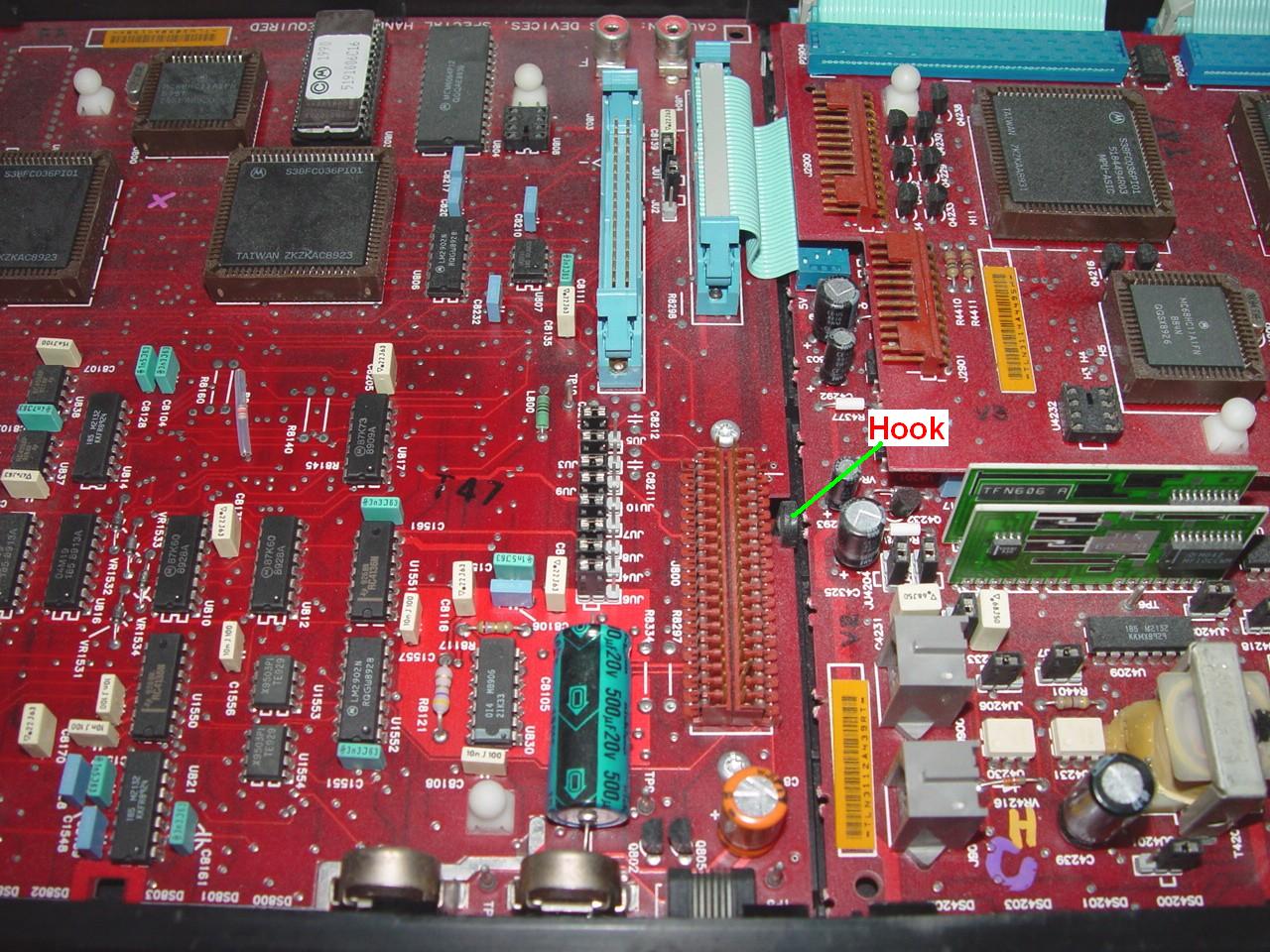
There's one additional "hook" on the control tray that holds the SSCB to the tray next to the expansion jack; it's at the end closest the TTRC. This will probably clear the slot by itself but it's worth noting that it's there and you'll have to deal with it during reassembly.
Lift the entire board out starting at the power supply end. The TTRC is considerably easier; pop the front panel out (there are only three tabs along the edges), slide the boards forward, lift the rear edge up, and remove the boards. There's no need to separate the logic board from the analog board.
Reassembly and Things to Watch Out For:
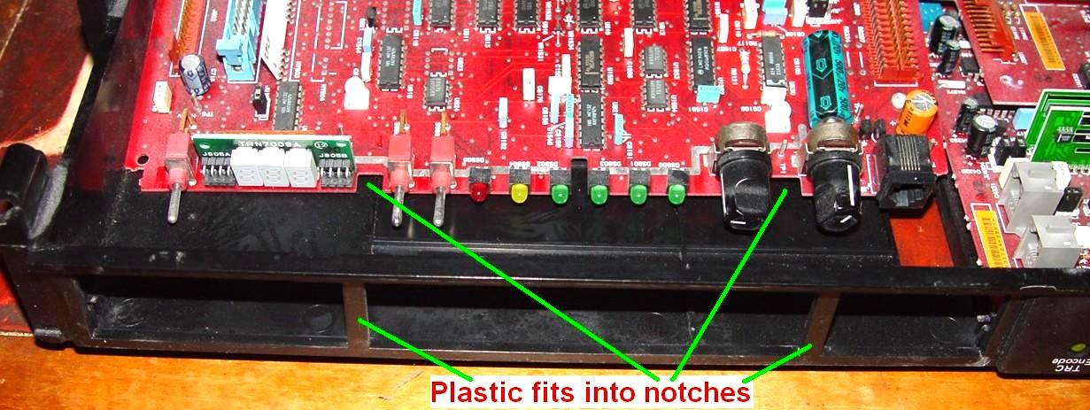
Reinstall in the reverse order. Slide the board into the control tray towards the front as much as possible, lower it then slide it towards the back. Make sure the "hook" next to the expansion jack fits into the small slot in the SSCB made for it. This helps hold that end of the SSCB to the control tray next to the expansion connector, to prevent board movement when you plug something into the expansion connector. Once the board is in place, you have to carefully fold the front panel back into the opening.
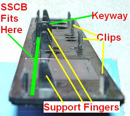
The board has to fit into the area reserved for it inside the back of the panel. Here's an edge view showing the clips, keyway, and support fingers, and where the SSCB has to fit.
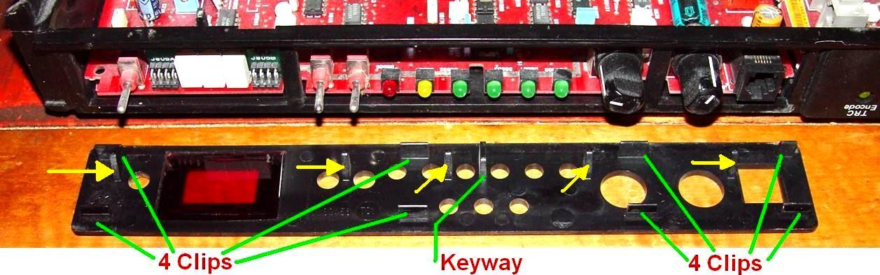
Start at the bottom edge with the lower tabs sliding under the board. Line up the switches, LEDs, and knobs, and especially the modular control jack, then work the top of the panel back into the opening, making sure everything is centered in its opening. It must fit flush. In the photo below, four of the plastic clips fit UNDER the SSCB and the five plastic fingers - pointed out in yellow - must go on TOP of the SSCB.
Gently roll the front panel inward making sure everything is in the proper position. It might take two or three tries, but it will eventually snap into place and all the controls will be centered in the panel and the panel will be flush with the control tray. Again, you might break a tab or two in this procedure; that's life. I've tried gluing them back on with no success.
Hook the control tray back onto the RF Tray and flip the control tray vertical. You can then insert the swing arm's larger hole (Hole 2) over the post head, depress the spring, and slide the swing arm until the post head locks into position in the smaller hole (Hole 1). Reattach the cables, swing the control tray down, push the RF Tray back into the cabinet and secure it with screws.
Contact Information:
The author can be contacted at: his-callsign [ at ] comcast [ dot ] net.
Up one level (MSF index)
Up two levels (Moto index)
Back to Home
This article created 26-Feb-2014.
Article text, photos, and hand-coded HTML Copyright © 2014 by Robert W. Meister WA1MIK unless otherwise noted.
This web page, this web site, the information presented in and on its pages and in these modifications and conversions is © Copyrighted 1995 and (date of last update) by Kevin Custer W3KKC and multiple originating authors. All Rights Reserved, including that of paper and web publication elsewhere.