Up two levels (Moto index)
Back to Home
Miscellaneous Adjustments
By Robert W. Meister WA1MIK

|
Up one level (MSF index) Up two levels (Moto index) Back to Home |
MSF5000 896 MHz Repeaters Miscellaneous Adjustments By Robert W. Meister WA1MIK |
|
This is a set of Alignment and Adjustment Hints and Kinks specifically for the 896 MHz New Jersey MSF5000 repeater stations. These supplement the procedures given in the alignment section of the MSF5000 installation and/or service manuals. A certain level of expertise, plus access to the proper equipment and manuals, is mandatory.
Setting the Forward and Reflected Power Trip Points:
On the 896 MHz trunking repeaters, an external wattmeter is present after the circulator and low-pass filter. An alarm will sound 6 or 7 beeps every time the station is keyed if the forward output power is too low or the reflected output power is too high.
The Alignment section of the MSF5000 Service Manual details how to set these power limits from the front panel. The Station Alignments screen, documented in the RSS Manual, details how to set these from within RSS. Motorola strongly warns you NOT to try setting these alarm trip points on non-trunking stations, those that do not have an external wattmeter. They don't say exactly what kind of corruption will occur, nor how to recover from it. (Recovery is possible but not trivial.) External here means installed by the factory between the Power Amplifier and the transmit antenna jack and wired into the RCA jacks on the SSCB.
Contrary to what's documented in the Service Manual, you can set the forward and reflected power alarm trip points entirely from the front panel without a Diagnostic Metering Panel. You don't need the DMP to cause the station to transmit, although having one means you don't have to hold the Xmit switch during most of this procedure. Here are the steps involved.
You may get alarm codes 6 or 7 during this procedure. Ignore them for now. They will go away after you finish the last step and have set the forward power high enough.
If you will be running your station close to the alarm trip points selected here, make appropriate adjustments to the values you use to maintain the 35% and 20% range.
Adjusting the 14.4 MHz Reference Oscillator in the HSO chassis:
The 14.4 MHz oscillator inside the HSO chassis can be adjusted through access holes in the top cover of the unit. It takes a minute to get to the test point, 10 seconds to measure and adjust it, then another minute to put the chassis back in place.
Aligning the Front End:
The book recommends using the tuning probe. This really is the only way to go. Follow the steps exactly and do NOT go back over adjustments you've already made. You'll actually diminish the receive sensitivity. The peak/dip method of tuning adjusts each section of the front end to precisely the resonant point. A sharp dip is very easy to see; a broad peak is not.
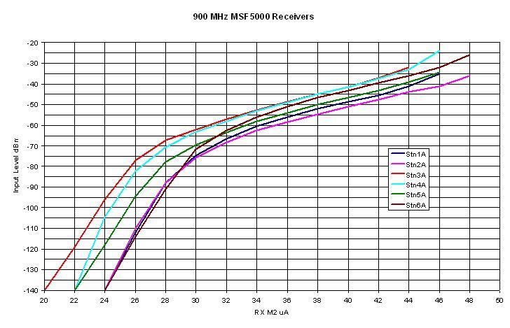
Depending on the station, the value you get on meter position #2 with no signal could be anywhere from 10-30 uA. The manual says a typical value is 10-15; the 896 MHz stations I worked on had 20-24 uA.
The metering circuit is extremely insensitive to small changes in signal level at the lower end of the scale. Feed in enough signal to fully saturate the station (M2 stops increasing); I found this to be in the range of 44-48 uA. Then reduce the signal to get a reading around 40 uA, and keep it there as you move the tuning probe through the front end. A 20dB change in input level will cause the meter to move from 44 to 32 (a difference of 12 uA), but it may only move from 26 to 24 (a difference of 2 uA) if you work down at the low end of the scale. This makes tuning very difficult. So use a lot of signal (around -20dBm into the tuning probe) but make sure the receiver is not saturated.
The graph below shows the meter sensitivity on six different stations when the RF signal is fed into the antenna jack. The tuning probe provides about 30-40dB of loss, so to get an effective signal input of -60dBm, you need to feed -20dBm into the probe.
Quick Transmit Deviation, Repeater Gain, and Flutter-Fighter Adjustments:
I used my RF signal generator to provide modulated RF. This unit can also send the modulation audio out another jack, so I used it as my audio oscillator as well. I set the parameters to 1.0 kHz sine wave tone, 1.0 kHz deviation, and 1.42 Vpeak (the book calls for 1.0 Vrms). The RF output of the signal generator was set to 1 mV and it was connected to the RX antenna input on the station. The TX antenna output of the station was connected to a wattmeter and dummy load, and a signal tap fed a sample to the deviation meter. I plugged the flat cable of a diagnostic metering panel into the station and raised the control tray. All EEPot adjustments were performed via the front panel.
CW ID Doesn't Work:
The CW ID logic in the MSF stations is "polite" in that it won't send the CW ID if it detects activity on the channel. It uses the Receiver Squelch circuit to do this. Since there's no LED indicator on the station to tell you if the squelch is open or closed, you'll need a diagnostic metering panel or a PC/RIB/Cable connected to monitor the MUXBus.
Make very sure the RECEIVER SQUELCH (EEPot #3) is set tight enough with an antenna (or duplexer and antenna) attached to the receiver input jack. Adjust it to be solidly closed (LED off and not flickering) then bump the value higher by 4 or 5 counts.
If the R1 UN SQ LED is flickering or on, it will prevent the CW ID from playing at all, and unless you've got a DMP attached, you won't know why.
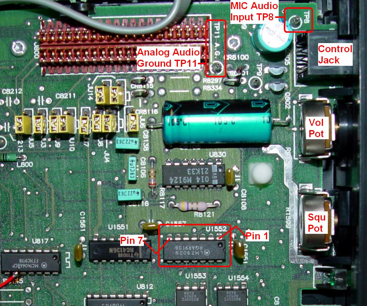
U1552 on the SSCB is a quad op-amp. Two sections of it provide a great place to probe with just about any analog or digital indicating device (VOM, VTVM, DMM, scope, etc) if you don't have a computer or DMP handy. The chip is located directly behind the front panel's Squelch control and is out in the open, so it's easy to access. The important signals are all active low (under 0.1V) and this occurs when sufficient signal opens the respective squelch circuit. They both sit around +8V when the squelches are closed. It would be trivially easy to add a small LED and resistor to each of these two lines, drawing about 10mA, so you can see if the squelches are open or closed, just by looking at the SSCB. The following data lists the pins and signals you can measure.
The photo above shows the upper right corner of the SSCB, with U1552 pins 1&7 marked.
IF AGC Adjustment Hints:
The alignment section has a very straightforward procedure. You will probably have to remove the top cover from the RF Tray to access the adjustment pot. The problem is finding TP12 and TP13 on the SSCB. They're at the hinged end of the board, behind the bundle of cables, and not easy to see. TP13 is next to the 5V switching regulator transistor's heat sink. It's easier to attach your meter's test leads to them if the station is un-powered, so you can move the bundled cables out of the way without disturbing anything. Make sure everything is fully plugged in after you connect your meter. Put the positive lead on TP13 (the one closer to the rear of the station) and the negative lead on TP12 then adjust the pot for 0.60VDC under the appropriate test conditions: 1 mV RF, 1 kHz sine wave tone, 1.5 kHz deviation.

Tuning the VCOs:
When you increase a programmed frequency via RSS, the synthesizer increases the VCO's steering line (SL) to raise the operating frequency. The normal metering value (M5) is 38 +/- 2 microAmps on the highest frequency. Most repeaters are only programmed with one frequency so this doesn't matter. The VCO and synthesizer can perform with the steering line in the 12 to 42 uA range. All the MSFs I've ever worked on tend to have a lower SL indication as they heat up.
Turning the adjusting coil counter-clockwise (CCW) will raise the operating frequency of the VCO, thus resulting in a lower SL meter indication. Conversely, turning the coil clockwise (CW) lowers the operating frequency. Both the Receive and Transmit VCOs operate this way, although only the TX VCO accepts modulation.
I was reprogramming an 896 MHz station from 927.41250 MHz and accidentally set the TX IDLE Frequency to 902.81250 MHz (the new receive frequency) rather than 927.81250 MHz (the new transmit frequency). After the station rebooted, the TX VCO LOCK LED did not light up, so I proceeded to adjust the TX VCO coil. I started turning the VCO core clockwise to bring the meter indication up to 38 uA. It took over 5 turns, which seemed odd since I was only moving the operating frequency 400 kHz. That's when I looked at the code plug data on the RSS screen and discovered that the TX IDLE Frequency had been set far from where it should have been. Surprisingly the VCO worked fine, however I doubt the rest of the transmitter would have functioned. I did not try transmitting. Once I reset the TX IDLE Frequency properly, the VCO core required 5 turns CCW to bring it back to the right range.
Contact Information:
The author can be contacted at: his-callsign [ at ] comcast [ dot ] net.
Article text, photographs, and hand-coded HTML © Copyright 2008 By Robert W. Meister WA1MIK.
Up one level (MSF index)
Up two levels (Moto index)
Back to Home
This article first posted 07-Jul-2008
This web page, this web site, the information presented in and on its pages and in these modifications and conversions is © Copyrighted 1995 and (date of last update) by Kevin Custer W3KKC and multiple originating authors. All Rights Reserved, including that of paper and web publication elsewhere.