Motorola index
Back to Home
for Digital-Capable Stations
By Robert Meister WA1MIK
Maintained by Mike Morris WA6ILQ

|
MSF index Motorola index Back to Home |
MSF5000 Programming Cable for Digital-Capable Stations By Robert Meister WA1MIK Maintained by Mike Morris WA6ILQ |
|
The digital-capable (CXB and RLB) and analog-plus (GFB) stations are programmed with Motorola's Radio Service Software (RSS), product RVN4077G. This is a DOS program; it will NOT run in a DOS box or under any version of Windows operating environments. It probably will not run with a USB-driven serial port, or a laptop plug-in card with serial ports. I've always had real serial ports on my programming computers.
Analog (CLB and JLB) stations use a 2732-style EPROM to hold the station's code plug. An R1800-series suitcase programmer is required to change parameters like frequency, coded squelch, CW ID, etc. These stations do not use RSS and do not make use of any programming cable described here for routine station programming.
A Few Words About RIB-Less Cables:
Recently some people have decided to market so-called RIB-less programming cables for the MSF5000. As the radio interface is equivalent to what has already been used successfully for many other Motorola radios (MaxTrac, GM300, CDM-series, etc), it makes logical sense to just attach the appropriate connector on a cable and sell it.
The electronics inside these cables needs power to operate. This power can come from several sources: the computer itself, a battery, or an external power supply (i.e. wall-wart or a bench supply). Some of these cables make provisions for alternate power; others do not, relying entirely on signals available on the computer's serial port.
Typically, there are two hand-shaking lines on the serial port that are capable of supplying limited power to an external device. At least one of these lines needs to be high to power the electronics in the RIB-less cable. The RSS does NOT set any of them high, however on some computers, these lines are configured by the BIOS and can be set high all the time. I suspect that if your computer doesn't let you force any of these lines high, that a RIB-less programming cable, powered by just the computer, will not work. I know of at least one person who bought such a cable and is now returning it because it would not function with his setup. I don't know whether that particular cable was defective, or there was no alternate way to power the electronics.
At the time of this writing (2006) you can buy a good quality RIB for about $40US. You can make a programming cable for an MSF for about $10US. Chances are, you'll eventually need to program another Motorola product in your lifetime, and you'll be happy to have a separate and universal RIB.
Equipment Requirements:
Communications between the station and programming computer takes place at 1200 baud. Computer speed should not be a problem with this software. I've used an 850 MHz laptop and never had any trouble.
The programming computer's standard serial port (COM1 or COM2) connects to a Radio Interface Box (RIB) through an appropriate, standard serial cable. These items are discussed in other articles. The RIB also requires a cable to connect it to the target radio's programming port. This cable is the subject of this article.
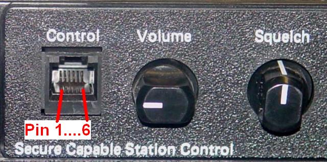
The MSF5000 station uses two signal lines for programming: IPCB (Inter-Processor Communications Bus) and Logic Ground. These signals are available at the Control jack on the front of the control tray and at the Expansion Connector on top of the control tray (or expansion chassis if present). The Control jack can accept a microphone, handset, or a programming cable. The Expansion connector can accept a metering panel cable or a programming cable. Given the choice, I'd rather use the Control jack on the front of the control tray. It's also easier to make a cable for the control jack.
Radio Connector Configuration:
The radio end of the cable depends on which connector you use. For the Control jack, pin 6 is the IPCB signal and pin 1 is the Logic Ground signal. If you can find an existing 6-conductor cable with the plug already crimped onto it, use that. Try to get one that is made with stranded wire; it's more flexible and will last much longer than solid wire in this application. If you make your own, you can use round or flat cable. You'll find connectors for both wire types; stranded is better. Here's the pin orientation for this connector:
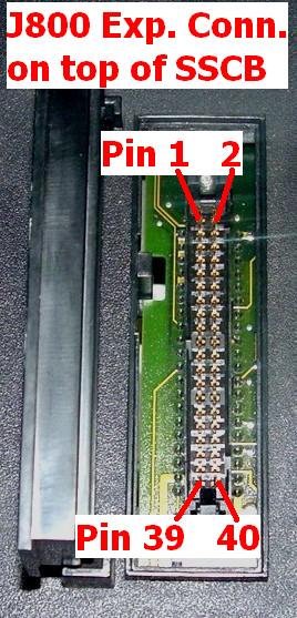
For the Expansion jack, pin 11 is the IPCB signal and pin 21 is the Logic Ground signal. You will need the connector body, two connector pins, and probably a strain relief which you can use to pull the connector out when you're done programming the station. Assembling all of this is a lot more work than even crimping one RJ11 plug. Here's the pin orientation for this connector:
RIB-End of the Cable:
The RIB end of the cable is a DB25 female connector. The IPCB line goes to pin 15 and the Logic Ground signal goes to pin 1. You will also need a short jumper between pins 4 and 11 on the DB25 connector. That's it: two wires and a jumper.
For those of you who have built programming cables in the past, the wiring of the RIB-end is exactly the same as you'd use for a MaxTrac, Radius, GM300, GTX, and several other Motorola two-way radios.
Radio-End of the Cable:
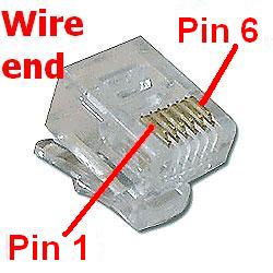
The radio end of the programming connector can be a 6-pin, 6-conductor (6P6C) RJ11-style modular telephone connector (sometimes called an RJ12 or RJ25 plug) or a dual-row 40-pin in-line female connector. The Motorola RSS manual specifies one cable, p/n 0180355A30, which plugs into the 40-pin expansion jack on the station control tray.
The modular connector plugs into the Control jack on the front of the station. This jack can also accept a microphone or handset to be used for local operation. Normally nothing is plugged into this jack, making it available almost exclusively for programming. Here is a typical 6P6C connector:
This radio-to-RIB cable is essentially the same as one used for a MaxTrac, GM300, or similar radio that uses an RJ45 (8P8C) plug on it. The MSF5000 just uses an RJ12/RJ25 (6P6C) plug and six-conductor wire. It should cost nearly the same to make either cable, so don't get ripped off if you buy a pre-made one. You could even buy one of these RJ45 programming cables, chop the end off, crimp a new RJ11 connector onto six of the eight wires, then rewire the DB25F connector to turn it into an MSF5000 cable. Another option is to make an adapter for your MaxTrac/GM300 programming cable using an RJ45 jack and a length of flat telephone wire with a a RJ12/RJ25 male plug on the end.
The 40-pin connector plugs into the expansion jack on top of the control tray (or expansion chassis if present - same connections, different location). This jack could be occupied by a cable going to a diagnostic or radio metering panel. Normally nothing is plugged into this jack, however when the station is on the bench it is much more likely to have a meter plugged in, making it inconvenient to use for programming. These are 0.100 inch (2.54 mm) spacing dual-row connectors, similar to the AMPMODU shown below (this one is 20-pin dual-row; you need a 40-pin dual-row plus two contacts). These connectors don't always have a convenient pull-tab for removal, making them difficult to insert and take out. Because of all the troubles, I recommend going with the RJ11-style instead, but you may see either kind for sale once in a while.
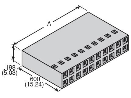
A very similar connector is available for 40-conductor flat wire. These are commonly known as IDC (Insulation-Displacement Contact) connectors and are the same style as are used on computer hard drives and floppy disks. Since you only need two wires, this type connector and wire is not cost-effective for use as a programming cable.
Connect the proper wire for the IPCB and Logic Ground signals to the appropriate pins on the DB25F connector that attaches to the RIB. The following table shows the connections.
| MSF5000 Programming Cable Wiring | |||
|---|---|---|---|
| RJ11 Ctrl Jack | 40-pin Exp. Jack |
Signal Name | DB25F to RIB |
| 6 | 11 | IPCB | 15 |
| 1 | 21 | Log. Gnd. | 1 |
| --- | --- | (Jumper) | |
There's a 50% chance that you'll get the cable wired wrong. It doesn't seem to do any harm other than to reduce your ego a notch or two. After you make the cable, plug it into a working station and measure the DB25 end pin 15 with a DC voltmeter; you should get about +5VDC here to any chassis ground point on the station. You should get 0VDC on pin 1. If these are reversed, you need to swap these two wires in your cable.
Alternatives:
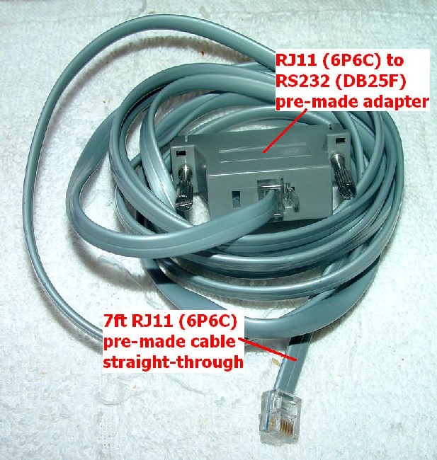
You can also buy a modular-to-RS-232 adapter and a pre-made cable. You will want a 6P6C RJ11-style connector and a DB25 female in the adapter; the photo below shows the Jameco DB25F-to-RJ11 (6P6C) adapter (p/n 66245) for about $2.59:

The cable can be any length, although 7 ft is probably too long. There are two types of cables: those wired straight through, and those that are reversed. In this application, you want a straight-through cable - oddly one that requires the connectors to be flipped over on the flat cable (one tab faces you, the other is away from you when the cable is stretched out on a table). If you look very carefully you will see that the same wire color is on pin 1 of each connector when you hold them up to view them. The proper RJ11-6P6C, 7ft cable, style 2 (straight-through wiring, Jameco p/n 115617) sold for about $2.19 in late 2006. Here's a photo of the completed assembly. Note the connector tab is on the smooth side of the cable at one end and on the ribbed side at the other end.
Plug the cable into the adapter and use an ohm-meter to find the appropriate wire inside the adapter for the IPCB and Logic Ground signals. On my adapter, the blue wire is plugged into the DB25F pin 1, while the white wire is plugged into the DB25F pin 15. Check your adapter first because once the wires are inserted, they are very difficult to remove. Cut off two of the unused wires from the RJ11 jack, solder them together as a short jumper, and insert them into pins 4 and 11 of the DB25F connector.
I've been told that big national discount stores often have RJ11/RJ12 6P6C telephone cords in various lengths. Buy a short one, chop it in half, figure out which wires go to pin 1 and pin 6, and solder them onto a DB25F connector. Do this to each half; you can make two cables out of one telephone cord!
You could also solder the wires on one of these cords to an existing MaxTrac (RJ45) programming cable's DB25F connector.
Other Information:
This same RJ11/RJ12 cable can also be used with the Multi-Coded Squelch (MCS) module that would occupy space in an expansion tray.
The programming software seems to be quite happy running on computers up to nearly 3 GHz, according to posts from several users on newsgroups. However, newer computers seem to be doing away with the standard serial port, so speed may not be as much of an issue as the inability to plug the RIB into something.
Acknowledgements and Credits:
MSF5000, RSS, MaxTrac, Radius, GM300, GTX, and RIB are all trademarks of Motorola, Inc.
AMPMODU is a trademark of Tyco Electronics Corporation.
Pin connections came from studying various Motorola MSF5000 service manuals and from actual station measurements.
Contact Information:
The author can be contacted at: his-callsign [ at ] comcast [ dot ] net.
Back to the top of the page
Up one level (MSF index)
Up two levels (Motorola index)
Back to Home
This page originally posted on Monday 11-Dec-2006
Photographs, article text, and hand-coded HTML © Copyright 2006 by Robert W. Meister WA1MIK.
This web page, this web site, the information presented in and on its pages and in these modifications and conversions is © Copyrighted 1995 and (date of last update) by Kevin Custer W3KKC and multiple originating authors. All Rights Reserved, including that of paper and web publication elsewhere.