Up two levels (Moto index)
Back to Home
MSF5000 Stations
Compiled, HTML'd and Formerly Maintained by
Robert Meister WA1MIK (SK)
Photos by the author unless noted
Currently Maintained by Mike Morris WA6ILQ

|
Up one level (MSF index) Up two levels (Moto index) Back to Home |
A Photo Tour of the MSF5000 Stations Compiled, HTML'd and Formerly Maintained by Robert Meister WA1MIK (SK) Photos by the author unless noted Currently Maintained by Mike Morris WA6ILQ |
|
| The photos in this write-up are all thumbnail photos. If you click on the thumbnail the corresponding large photo will be displayed at full browser size. |
This is a big article. Click on the links below to go directly to that topic, area, or section.
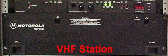
This article takes you through a photo tour of the Motorola MSF5000 UHF station, in particular, these three units:
Additional photos show a 150w 896 MHz ("900 MHz") trunking repeater and its high-stability oscillator. There are also some pictures of assemblies from VHF stations where they differ from others.
System 1 was the subject of most of the photos and was the basis for most of the article. The tour follows a top-down, or outside-in approach. Pictures start with the cabinet and work their way into the station as deep as I could go to show the major components. Some items will be mentioned before their turn comes up in the tour; just bear with me and read the text again after you've been through it once. (That's one problem with the top-down method.)
This article will NOT be an in-depth memory dump of everything I know about these stations nor everything anybody else knows. First, I am not an expert. Second, I've only repaired or worked with five UHF stations in the past few years and may not have encountered every possible configuration. Third, the photo tour is meant to give the viewer enough information to determine whether the station is digital-capable or analog, and to recognize the major components. If you have one of these stations, try to buy the manuals now while they're still available. If not, we have downloadable PDFs.
If you have a manual that we don't please let the page maintainer know.
For those of you who are in too much of a hurry to read the entire article, here is a short summary of the major differences between the two model series:
| Analog (CLB or JLB) | Digital-Capable (CXB, etc) |
|---|---|
| Older, less desirable | Newer, more desirable |
| Usually less expensive | Usually more expensive |
| Programmed via EPROM | Programmed via RSS |
| Uses suitcase programmer | Uses a PC and a RIB |
| Long reprogramming cycle | Short reprogramming cycle |
| Can't do secure (encryption) | Can do secure (encryption) |
| No 7-segment LED display | Has 7-segment LED display |
| Mechanical potentiometers | Electronic potentiometers |
| Multiple remote control boards | One set of boards for all apps |
| Limited diagnostics | Extensive diagnostics |
The model number follows the "old" format. This information is directly from the Digital-Capable Instruction Manual. Digital-capable implies the ability to run secure (encrypted) communications. Secure is NOT possible or available on 896 MHz stations; the Digital-Capable station for that band is called Analog Plus. (Motorola 896 MHz stations cover the 900 MHz amateur band.) I've split it into two pieces so it's more readable. I don't believe all bands were available as analog. To my knowledge, MSF5000s were only made for bands 3, 4, and 5.
First six characters (before the hyphen): (the bottom row shows the most common or popular values)
| Housing | Power [1] | Band (MHz) | Series | Voltage |
|---|---|---|---|---|
| B: Base | 0: no TX | 0: under 25 | CL: Analog | A: 12DC Ext |
| C: Compa | 1: less than 0.75 | 1: 25-54 | CX: Dig.-Cap. | B: 120AC |
| N: Rack | 2: 6w | 2: 66-88 | GF: Analog Plus | C: Battery |
| 3: 15w | 3: 132-174 | RL: Limited [2] | D: 120AC, 12DC | |
| 4: 40w | 4: 406-512 | RU: Canada [3] | G: 120/240AC, 12DC | |
| 5: 70w | 5: 806-960 [4] | K: 120/240AC | ||
| 6: 100w | 7: 1.5 GHz | |||
| 7: 135w | 8: 280 | |||
| 8: 260w | ||||
| 9: more than 260 | ||||
| C | 4, 6, 7, 8 | 3, 4, 5 | CL, CX, RL [5] | B |
Notes:
[1]: While the power shown is the maximum power for that range, the stations are
typically rated for, or operated at, lower power levels. For example, a C64 is rated
for 80 watts, a C74 is rated for 110 watts as a base station but only 85 watts as a
repeater, and power range 8 is actually 225 watts for VHF and UHF stations, and 150
watts for 800/896 MHz stations. Not all power levels are available for all bands.
[2]: From the MSF5000 Instruction Manual update: "The MSF Limited line of base and
repeater stations is identical to the standard MSF5000 model line with one exception:
very few factory installed options are available. All other specifications, hardware,
and software are identical." This means an RLB station is the same as a CXB station.
[3]: These stations are also digital-capable and seem to be identical to the CX and RL
models.
[4]: Both the 800 MHz and 896 MHz MSF stations are in band 5; it wasn't until after the
MSF line that the 896 MHz units became band 7.
[5]: If the first letter is a J then it was built as a paging station and may or may
not have a receiver. If it does have a receiver is may not be in the same frequency
band. It may have a wireline digital modem instead of a receiver, or it may have been
connected to a satelite modem.
Last six characters (after the hyphen): (the bottom row shows the most common or popular values)
| Squelch | Ch Spacing | # Ch | Control | Version | Variation |
|---|---|---|---|---|---|
| 1: CSQ | 0: wide | 0 [1] | 0: None | A: older | R: Rack Mnt |
| 2: Data | 1: 25 kHz [2] | 1: Data | B: newer | T: Repeater | |
| 3: PL | 2: 12.5 kHz [2] | 2: No Ctrl | blank: Base | ||
| 5: Connect Tone | 4: extender | 3: Local | |||
| 6: DPL | 4: EXT local | ||||
| 7: Programmable [3] | 5: DC [4] | ||||
| 6: Tone [4] | |||||
| 7: DC & Tone | |||||
| 8: TAC RX [5] | |||||
| 7 | 1 | 0 | 5, 6 | A, B | blank, T |
Notes:
[1]: Even though it specifies zero channels, the stations can have three channels, and
with additional code plug memory can handle 16 channels.
[2]: This position officially specifies the channel spacing, however it also indicates
the modulation acceptance and deviation of the station. VHF, UHF, and 800 MHz stations
are 5 KHz bandwidth, but can be programmed on 12.5 KHz channel increments. 896 MHz
stations are 2.5 KHz bandwidth. This same meaning holds true for the analog (CLB)
stations and is one way to separate 800 MHz from 896 MHz, since both use "5" for the
band specifier.
[3]: Programmable squelch means the station can do carrier, PL, or DPL on any channel,
and the transmit mode can be different from the receive mode.
[4]: The digital-capable TTRC (Trunking Tone Remote Control board) can be jumpered
and configured in the field for DC or Tone.
[5]: TAC is Motorola's receiver voting system ("Total Area Coverage").
A typical model number, C74CXB-7106BT, decodes as follows: Compa-station, UHF, 135 watts (maximum, typically 110 watts), Digital-Capable, 120VAC power, programmable squelch, 25 KHz channel spacing, tone remote control, revision B, repeater.
As always, there are exceptions and violations of the model naming convention. If you see the letters "SP" followed by two digits after any model or part number, this means the station has been modified for the original customer to perform a Special Purpose, so things may not be stock.
Selected Station Ratings and Specifications:
| Range | Freq (MHz) | Power Levels (Watts) | Deviation | TX BW [3] | RX BW |
|---|---|---|---|---|---|
| VHF-1 | 132-158 | 6, 25, 75, 125, 350 | 5.0 kHz | 26 MHz | 2 MHz |
| VHF-2 | 146-174 | 6, 25, 75, 125, 350 | 5.0 kHz | 28 MHz | 2 MHz |
| UHF-1 | 403-435 | 6, 15, 30, 75, 110, 225 | 5.0 kHz | 8 MHz | 2 MHz |
| UHF-2 | 435-475 | 6, 15, 30, 75, 110, 225 | 5.0 kHz | 8 MHz | 2 MHz |
| 800 MHz | [1] | 35, 75, 150 | 5.0 kHz | 18 MHz | 4 MHz |
| 896 MHz | [2] | 75, 150 | 2.5 kHz | 6 MHz | 5 MHz |
Notes:
[1]: transmit 851-869 MHz, receive 806-824 MHz.
[2]: transmit 935-941 MHz, receive 896-902 MHz.
[3]: the transmit bandwidth is significantly less when equipped with an internal
filter/duplexer.
High power stations (those running more than 125 watts of transmitter power - C8 and C9) need 46-inch tall cabinets and have two power supplies and two RF power amplifiers, although one is considered a driver for the other. All low power stations (those running 125 watts or less - C2, C3, C4, C6, C7) can fit into a 26-inch tall cabinet.
The standard 800 and 896 MHz stations are always repeaters; they can't be reconfigured as base stations to talk to repeaters in these bands. "SP" versions could be ordered for use as base stations however.
System deviation is normally set for 4.6 KHz on VHF, UHF, and 800 MHz systems. It is normally set for 2.3 KHz on 896 MHz systems.
Receive sensitivity is 0.25uV for 12dB SINAD except for UHF which is 0.35uV. A value of 0.5uV for 20dB quieting is also shown for all bands except VHF. Actual performance is usually a lot better. For example, my UHF stations reach 20dB quieting at 0.3uV.
Band 5 covers both 800 and 896 MHz stations, just as it does for MICOR equipment. The model number does not specify the VHF or UHF range (1 or 2). You need to locate a part number on the RF tray or read the station with RSS to determine this. In general, for assemblies that are range-specific (power amplifiers, IPAs, front end assemblies, mixer coils, VCOs), the last digit of the assembly number indicates the range: 1 or 2. Look for small stickers (usually yellow or orange) with part numbers anywhere on these components. The location varies; some assemblies will have part numbers stamped on them. The text points some out.
People have managed to get range 1 UHF stations to operate at the low end of range 2, but to do it properly would require modifying everything that processes RF, and with parts no longer available, this would be nearly impossible. In my opinion, it's just not feasible. Similarly, an 800 MHz station will not operate up at 896 MHz.
Note that stations with the internal filter/duplexer and/or triple circulator have their output power de-rated considerably, so a UHF station could run at 110 watts as a base station, but only 85 watts as a repeater. The following information was extracted from tables in the instruction manual:
| Model | Std. | F/D | Circ. | Both |
|---|---|---|---|---|
| C23CXB | 6 | 3.5 | 4.5 | 3.0 |
| C43CXB | 25 | 15 | 20 | 12 |
| C63CXB | 75 | 45 | 60 | 35 |
| C73CXB | 125 | 75 | 100 | 60 |
| C93CXB | 350 | N/A | 300 | N/A |
| C24CXB | 6 | 4 | 3 | 3 |
| C34CXB | 15 | 10 | 9 | 8 |
| C44CXB | 40 | 30 | 25 | 20 |
| C64CXB | 75 | 55 | 45 | 40 |
| C74CXB | 110 | 85 | 70 | 55 |
| C84CXB | 225 | 140 | N/A | N/A |
| C45CXB | 35 | 23 | 30 | 21 |
| C65CXB | 75 | 50 | 60 | 45 |
| C85CXB | 150 | 100 | 125 | 90 |
| C65GFB | 75 | 50 | 60 | 45 |
| C85GFB | 150 | 100 | 125 | 90 |
Notes:
1. See the chart at the top of this article for a breakdown of model numbers.
2. Power levels are in watts. N/A = Not Applicable.
3. "Std." is the power level for stations with a single circulator (standard in all power
amplifiers) and no internal filter/duplexer.
4. "F/D" is the power level for repeaters with the internal filter/duplexer.
5. "Circ." is the power level for stations with a triple circulator in the power amplifier.
6. "Both" is the power level for stations with an internal filter/duplexer and a triple
circulator in the power amplifier.
The receiver IF stage operates at 10.7 MHz on VHF and UHF stations. It operates at 21.4 MHz on 800 and 896 MHz stations.
The transmit VCOs operate at the carrier frequency on VHF and UHF stations. They operate at one half of the carrier frequency on 800 and 896 MHz stations and the signal is doubled in the IPA and injection amplifiers. These stations also use what Motorola calls a MOSAIC IC synthesizer. This will have significance only if you're programming a station for the first time. The receive VCOs operate similarly but the resulting frequency is lower than the carrier frequency by 10.7 MHz on VHF/UHF or 21.4 MHz on 800/896 MHz stations. (By the way, MOSAIC stands for "Motorola Oxide Self Aligned Implanted Circuits", whatever that means.)
896 MHz stations have Flutter Fighter and compander circuits in them, which are equivalent to the HearClear circuitry found in other 896 MHz radios. They can't do secure communications. The 896 MHz RSS-programmed stations are called Analog Plus (GF) and these are, in all other respects, digital-capable.
Take A Seat, Get Comfortable. The Show Is About To Start:
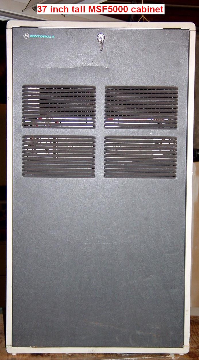
The first thing you will see is the gray louvered steel door, with a standard Motorola 2135 key lock at the top. The outer skin is beige coated steel, and a molded plastic piece forms the top and bottom of the cabinet. Several large Torx screws hold the plastic cover pieces in place. Cabinets can be stacked (there are limits) and bolted together in various configurations. These stations typically weigh 130-160 pounds; do NOT try to pick one up yourself - have a friend assist you. The high power (greater than 125 watt) stations tip the scale at 250 pounds. All stations are extremely top-heavy. The cabinets are 21 inches wide and 10 inches deep.
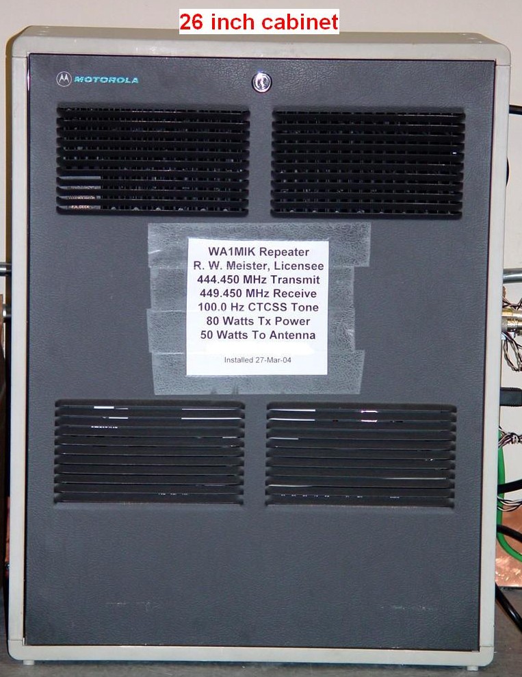
The 26-inch station is my operating repeater, hence the information sheet on the front:
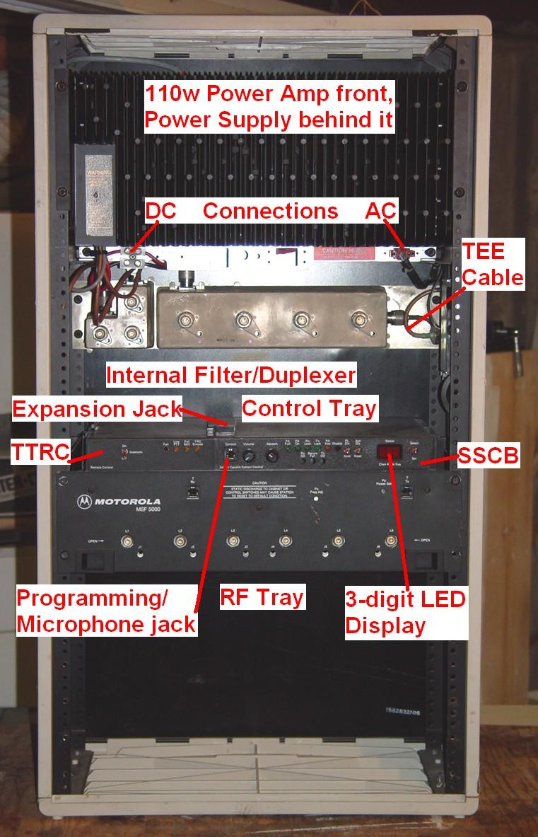
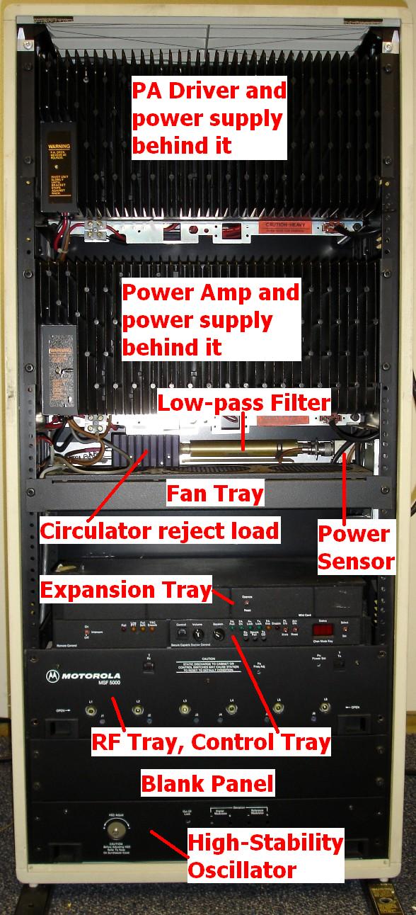
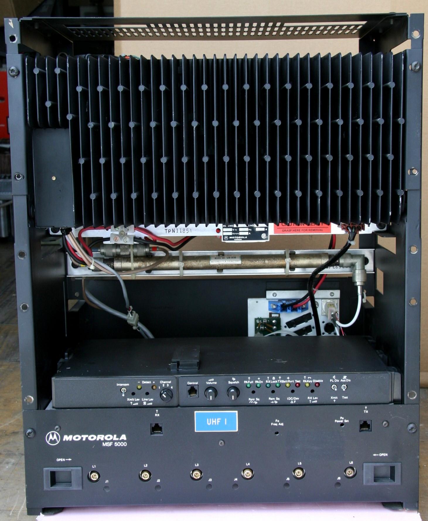
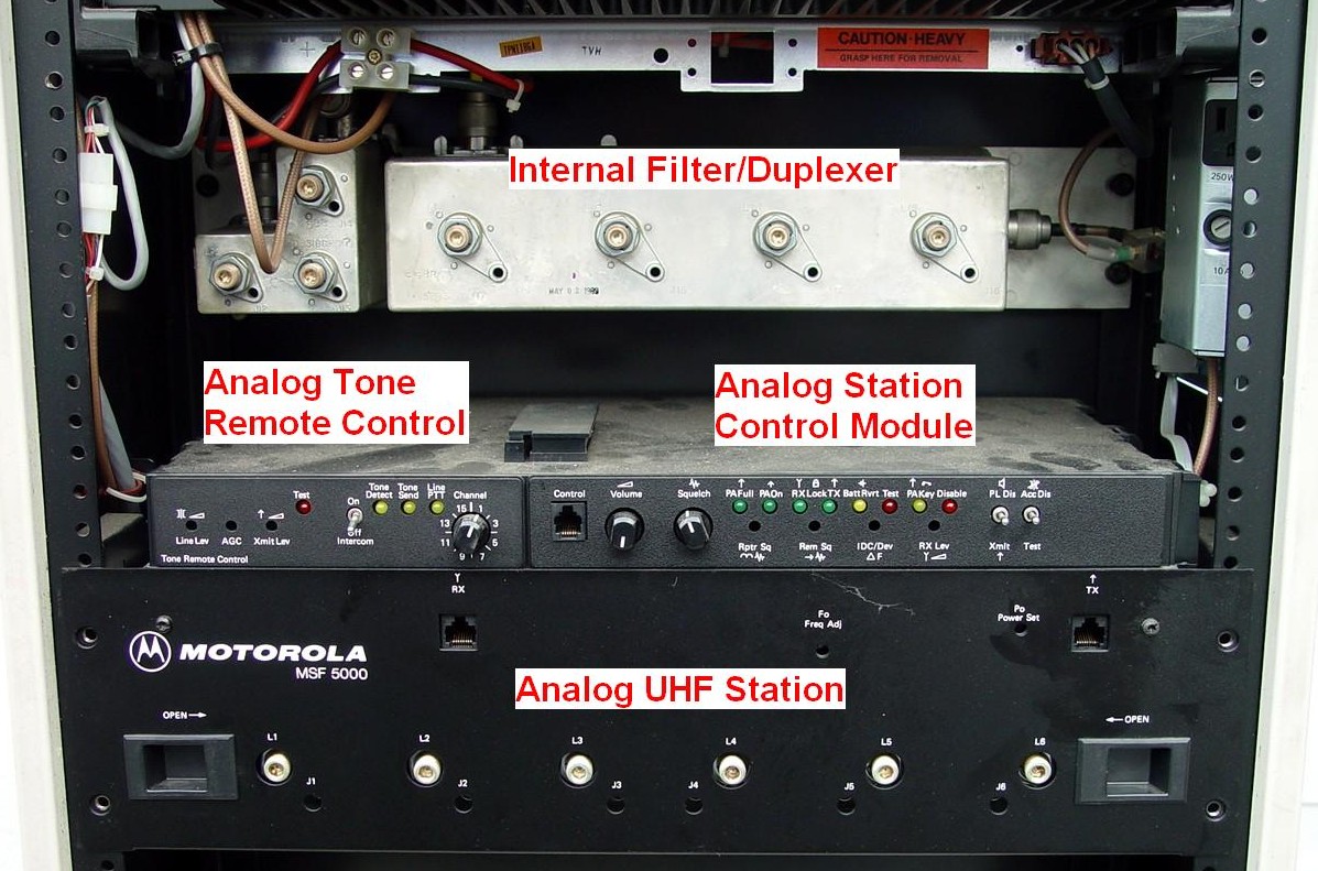
Once the front door has been removed, you can see the major components inside. The power supply and power amplifier are mounted at the top. Each one weighs about 40 pounds, and their placement makes the station extremely top-heavy. On high-power stations, those running more than 150 watts, an additional supply and power amplifier are mounted under the top pair. The bottom units are the RF tray and plastic control tray. A repeater station has an internal filter/duplexer and TEE cable under the power supply:
while a base station has a low-pass filter and antenna relay under the power supply:
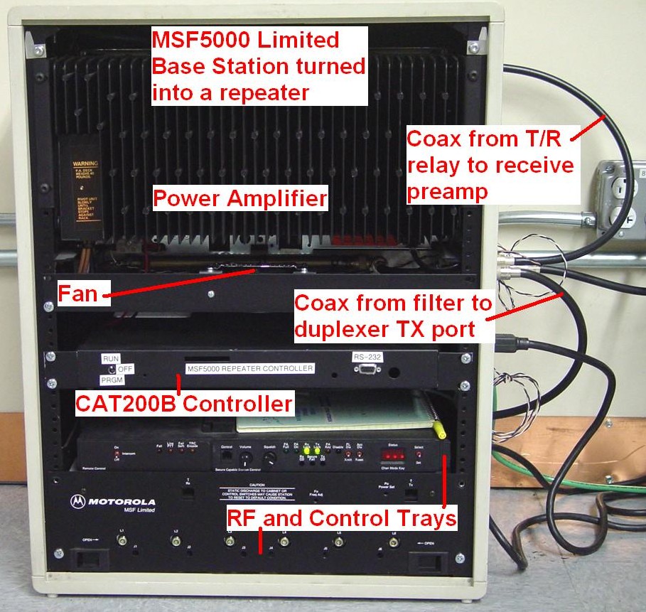
This base station has been converted to a repeater by disabling the antenna relay and adding an external Celwave duplexer (hanging on the back, not shown). I added a quiet 120VAC fan under the power amplifier to "stir" the air a bit; normally these stations are convection-cooled via the louvers in the front and sides of the cabinet. Motorola makes an official three-fan unit that mounts in the same place. They are powered by either 120VAC or 12VDC. I also added my own CAT200B repeater controller, primarily for DTMF control as required by FCC rules.
Here's a stock, high-power (150w) 896 MHz trunking repeater (C85GFB5203AT). Note there are even some anti-tipover feet at the bottom of the cabinet; this unit is extremely top-heavy. Roger W5RD supplied this photo:
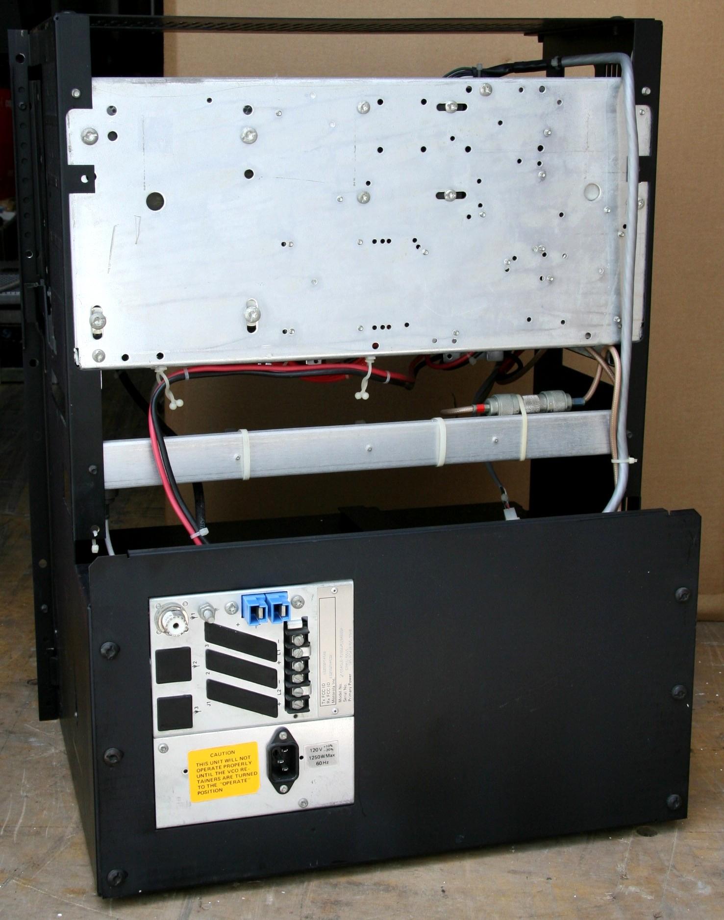
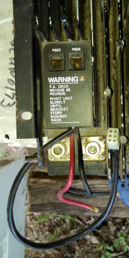
There are always variations. The following photos are of a Canadian open-frame UHF analog (CLB) base station with no wrap-around cabinet (photos supplied to repeater-builder anonymously):
The station junction panel is mounted on a chassis on the rear of the frame, rather than through the cabinet on the side. Note that this unit has battery-revert.
Now let's move on to examine each component separately.
Power supply and Power Amplifier:
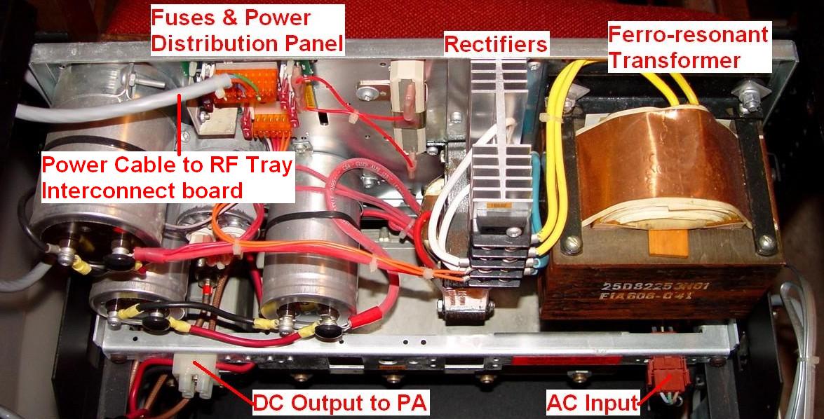
Once the white plastic top cover is removed (six long Torx bolts)), the outer skin can be lifted, spread apart slightly, and removed for easier access to several things. The internal steel frame is nearly 9 inches deep and supports all the assemblies. The holes in the frame rail are untapped; modules are attached with self-tapping M6x1.0 metric screws. Once tapped, you can use ordinary M6x1.0 machine screws. Starting at the top, we have the power amplifier in front (with a big finned heat-sink) that can be folded down on two hinge pins, and the power supply behind it:
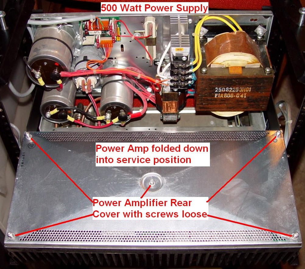
The power supply uses a ferro-resonant transformer and a full-wave rectifier to achieve relatively pure 15V DC at over 35 amps. This raw DC feeds the power amplifier directly through the terminal strip at the bottom left. Additional filtering and fuses are used to feed DC to the RF tray and any other accessories that need it. This power supply is terribly inefficient, but it is extremely robust and bulletproof. It is rated for 500 watts. Some units can also charge optional batteries. The transformer seems happy to operate on either a UPS or a generator, however the output voltage of all ferro-resonant transformers varies greatly with changes in the input power frequency. Without removing the power amplifier, here's what you can get to:
Battery-reverting power supplies provide charging current for various types of external batteries. Usually the station runs at lower RF output power when on batteries. The battery connects to similar DC Output terminal strips that the power amplifier is wired to.
Here's a photo of a VHF (28V and 14V) battery-reverting power supply supplied by Glen K6KJQ. Note the much more complex circuit board with the 120VAC circuitry under the metal shield.
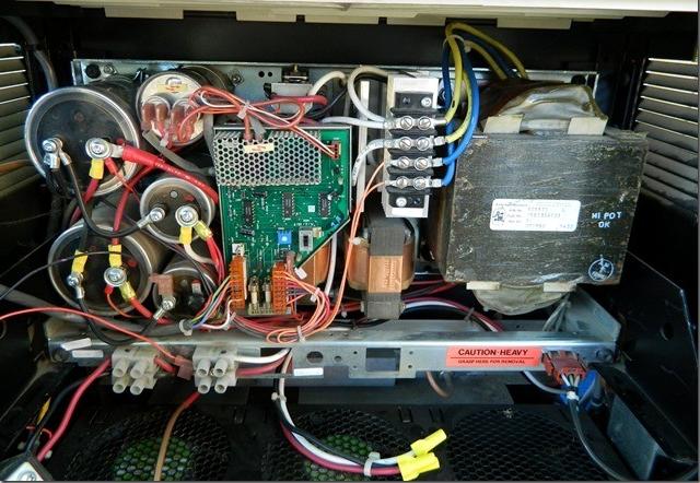
The VHF station supplies, for stations of more than 25 watts, put out both 14V and 28V; the latter is used just for the power amplifier. Battery-reverting power supplies for these stations require two 12V batteries and three connecting wires.
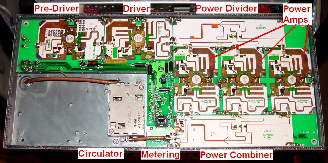
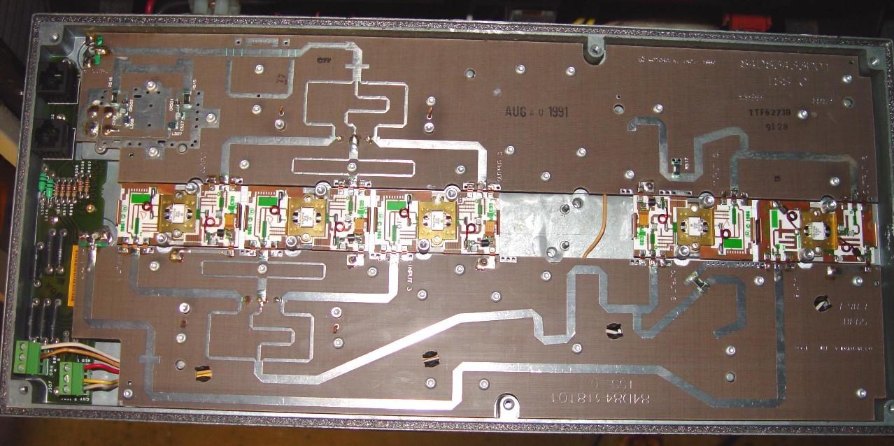
The 110-watt power amplifier consists of several modules, many of which are identical. The rear cover is held in place with five screws and is well gasketed. The power amplifier input is a male N connector on the end of a piece of coax. It enters the unit in the upper left corner of the photo below. A pre-driver and driver amplify the signal; this feeds a signal splitter that divides the power to feed the final amplifier modules. Each of these is good for about 40 watts. The output of the finals is combined to feed an internal isolator (a circulator with a built-in dummy load). The output of the isolator feeds another piece of coax with a male N connector on it:
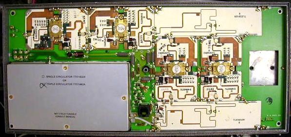
For comparison, here's a 75-watt power amplifier that has a triple circulator in the lower left corner. Note that there are only two final amplifier modules but the rest is quite similar. Steve KC6TLO supplied this photo:
Motorola put colored plastic bands on the input and output coax cables of most power amplifiers. The table below shows the color bands they used. Note that the UHF PAs don't seem to follow any convention. A 40w PA has RED for input; a 75w PA has RED for output; a 110w PA has RED for input. Some even say "RF INPUT" or "RF OUTPUT". Best thing to do is tie a label to one or the other. You can take the back cover off the PA and determine which is which with an ohmmeter, as the end of the input coax is readily accessible.
| Band and Power | Input | Output |
|---|---|---|
| 25w VHF | None | None |
| 125w/350w VHF | N Jack | N Jack |
| SOME UHF | Red | Yellow |
| SOME UHF | Yellow | Red |
| 900 MHz 75w Driver | Blue | Red |
| 900 MHz 150w Final | Red | None |
A six-position Molex connector passes signals representing the output power, heat-sink temperature, and isolator dummy load temperature to the interconnect board beneath the RF tray. They are used to control the output power of the station. These signals are tabulated below. Values are in DC volts referenced to ground:
| Pin | Color | Signal | RX | TX |
|---|---|---|---|---|
| 1 | Red | Heat-sink Temp. | 8.16 | 8.16 |
| 2 | Brown | Dummy Load Temp. | 5.52 | 5.52 |
| 3 | Orange | PA (not) Keyed | 7.91 | 0.14 |
| 4 | Green | Forward Voltage | 0.09 | 2.92 |
| 5 | Black | Signal Ground | 0.00 | 0.00 |
| 6 | White | Reflected Voltage | 0.00 | 0.00 |
NOTE: Pin 3 is Not Connected or Not Used by any of the PAs. Pin 6 is Not Connected or Not Used on Driver PAs.
On stations with a Driver PA and a Final PA, there will be two power supplies, two PAs, and two Molex connectors and cables. One cable will only have four wires; this goes to the Driver PA.
Apparently you can use an MSF5000 PA stand-alone by connecting A+ and ground to the big red and black power leads, ignoring the Molex connector, and feeding 2-4 watts of RF into the amp. Adjust the input power level as needed to control the output power.
Some power amplifiers have metering jacks on the front, which can be accessed without removing the rear cover. VHF power amplifiers higher than 25 watts run on 28V. Also, some VHF power amplifiers have female N connectors on the front rather than dangling pieces of coax with male N connectors at the end.
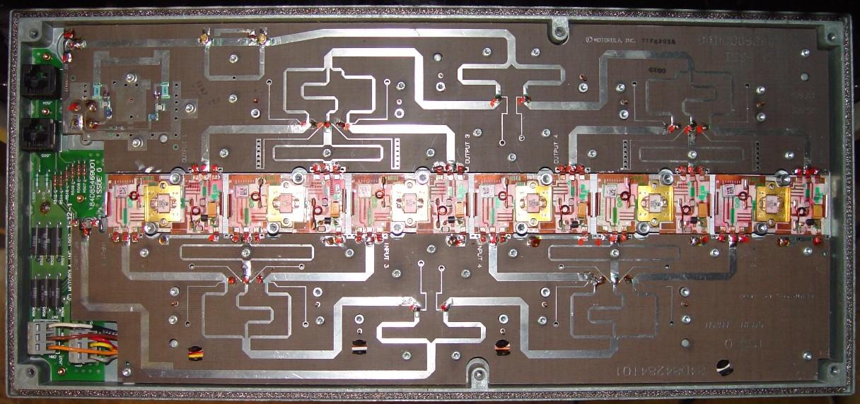
On high-power stations, the upper power supply and power amplifier are considered a driver. The RF tray supplies power to this unit. Below it is a second power supply and power amplifier that boost the power to the full 150-350 watts. Here's the (upper) driver power amplifier from a 150 watt 896 MHz station:
And here's the (lower) final power amplifier from a 150 watt 896 MHz station:
All of the MSF5000 power amplifiers run at full gain. The amount of RF input power determines the amount of RF output power. Typical drive power from the intermediate power amplifier in the RF tray is 3-4 watts.
As far as I know, the stations are specified for, and capable of, continuous transmit. High-power stations utilize one, two, or three AC or DC cooling fans in a tray below the PA.
You can put any power-rated PA into the station. The RF Tray controls the output power and the SSCB has no knowledge of the station's power level, other than a fault signal coming back from the RF Tray if the PA won't generate the power it is set to.
MSF5000 PAs don't all have the same hinged mounting hardware. The brackets that hold the power supply also have slots for the pins on the side of the PA. Some PAs have just one thin pin on each side while others have two thick pins. The vertical chassis rails might have slots cut in them for the second set of pins to pass through. All of the PAs I had encountered while writing this article had just one pin per side, but recently I ran across a much older analog (CLB) station that had two very robust pins on each side of the PA, and the PA wouldn't just fold down; it had to be raised about 1/4 inch to release the first/higher set of pins then flipped down on the second/lower set of pins. Of course the station that I wanted to put this PA into had the wrong mounting brackets and had no slots in the chassis rails to let the pins pass through.
Internal Filter/Duplexer (repeaters only):
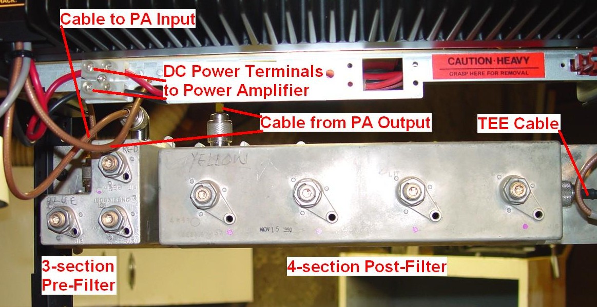
On repeater stations, the next major assembly is the internal filter/duplexer. This consists of a pre-filter, which has three band-pass stages, and a post-filter, which has four band-pass stages. The power amplifier's input signal runs through the pre-filter, while the power amplifier's output signal runs through the post-filter. These filters are tuned to the transmitter's frequency. The UHF unit has about a 2 MHz bandwidth. I have only seen these units on UHF stations, but real four-section duplexers were available for wide-spaced VHF stations and wide-band units were common on trunked 800 MHz stations:
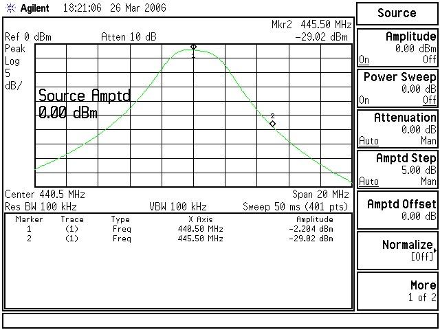
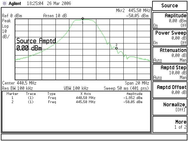
The three-section pre-filter has about 2dB of pass-band loss and provides about 30dB of attenuation of signals 5 MHz away from the transmit frequency. Here's the spectrum analyzer response of the pre-filter tuned to 440.5 MHz:
The four-section post-filter has a bit less than 2dB of pass-band loss and provides nearly 50dB of attenuation of signals 5 MHz away from the transmit frequency. The ripple around the receive frequency of 445.5 MHz is due to the receiver front end tuning. Here's the spectrum analyzer response of the post-filter tuned to 440.5 MHz:
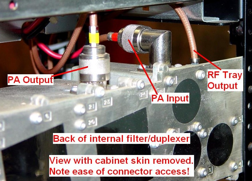
The connectors on the filter/duplexer are difficult to get to, and you need access to them during alignment. For this reason, it's easier to remove the outer skin of the cabinet. The coax lines ARE color-coded (or labeled), and you'll notice that I wrote these colors on the casting. Here's a view from the rear:
And here's a view from the left side:

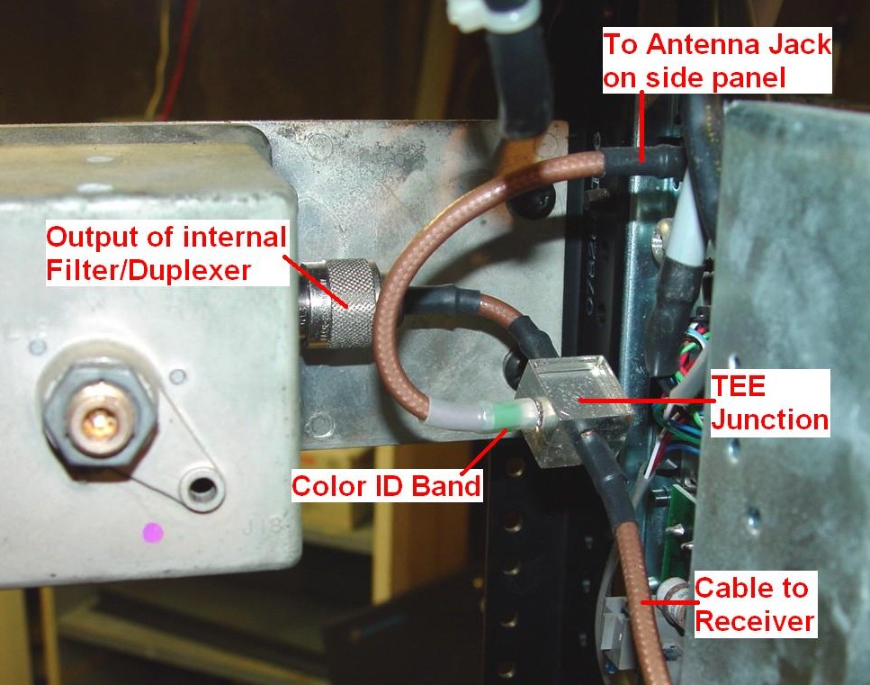
The output of the post-filter connects to one leg of a special duplexer TEE cable that merges the receiver and transmitter signals:
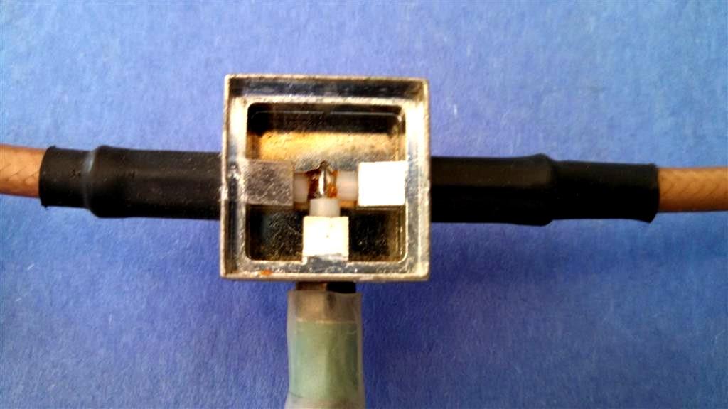
Mike Palmer KØHYT took the cover off the TEE cable's junction box to have a look inside. The photo below shows it's just a soldered connection of all three pieces of coax. In fact, on the real old stations they just used an ordinary N TEE connector and three coax cables.
Between the filter/duplexer, TEE cable, and receiver front end, sufficient attenuation of the transmitter signal is obtained to allow the station to operate full duplex as a repeater - but just barely. Careful tuning, by the book, is mandatory to achieve sufficient isolation.
Most commercial UHF repeaters transmit low and receive high. This relationship determines which of two cable configurations will be used. The location of the junction block and lengths of coax identifies the cable.

A colored band on the TEE cable tells the frequency operating range:

One common cable, identified with a green band on one piece of coax, covers the 435-475 MHz range where the transmit frequency is lower than the receive frequency. This cable, stretched out, is shown below (photo supplied by W9SL):
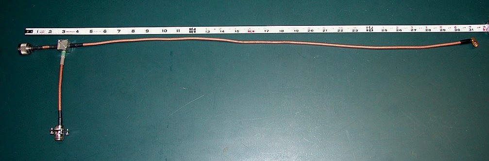
Some repeaters have a transmit frequency higher than the receive frequency. Here's a yellow band cable that covers the 435-475 MHz range, shown below (photo supplied by W9SL):
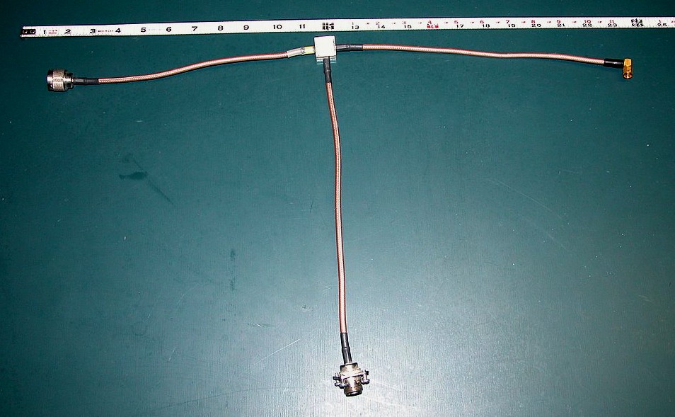
I obtained some anonymous information regarding the cable cut lengths but have not been able to match the physical lengths of the green or yellow cables to those specified in the supplied data.
The internal filter/duplexer can be bypassed if necessary, by using a double female N adapter between the RF tray IPA output and the power amplifier input, and by connecting the power amplifier output to the transmitting antenna or external duplexer. A suitable bypass cable would also be needed for the receiver.
I recently encountered a 75w analog (CLB) UHF repeater that had two antenna jacks on the junction box as well as an internal filter/duplexer. The receive jack fed the receiver directly and the output of the filter/duplexer fed the transmit jack directly. There was no TEE cable at all. This station obviously required an external duplexer.
Low-pass Filter (base stations only):
The UHF MSF5000 uses a Microlab/FXR LB-A70 low-pass filter (that foot-long tubular component), which claims to attenuate signals above 520 MHz by 55dB, to eliminate undesirable harmonics that are generated by the isolator in the power amplifier. This filter goes between the power amplifier output and the antenna relay input:
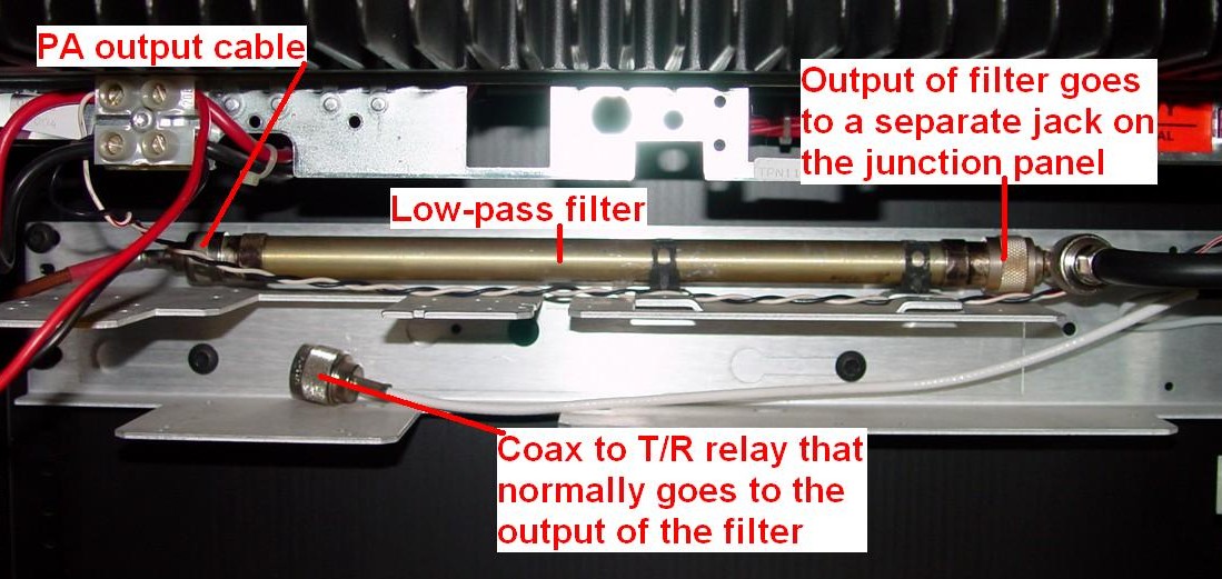
The white coax sitting under the low-pass filter goes to the antenna relay. It would normally connect to the right end of the low-pass filter. It is not connected because I have converted the station to a full-duplex repeater.
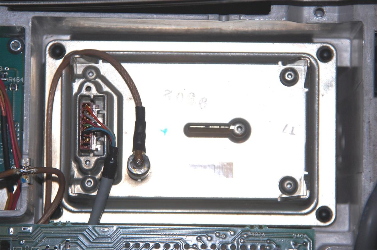
Base stations don't receive and transmit at the same time; therefore they share the antenna connection. The antenna (or transmit/receive or T/R) relay switches the one antenna connection between the receiver and the transmitter:
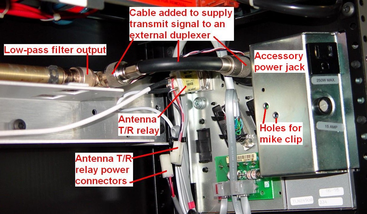
Note that in this photo, the antenna relay coil is disconnected. Also, the output of the low-pass filter is bypassing the antenna relay and going to its own jack on the junction box. This was done to turn the station into a repeater. The output connector on the junction panel is part of the relay assembly, and one coax cable with a male N connector goes to the low-pass filter, while another coax cable with a right-angle male SMA connector feeds the receiver on the RF tray.
On base stations, the RF tray IPA output goes directly to the input of the power amplifier through a double female N adapter.
VHF stations have a "peripheral box" located here. It's a low-pass filter with an optional antenna relay (present for base stations only). Here's a photo of a repeater version, that doesn't have the antenna relay, supplied by Bob VE3DJ:
Trunking stations could have an external wattmeter or RF power sensor connected after the low-pass filter.
896 MHz stations could have an additional isolator before the low-pass filter.
All base stations are capable of base or repeater operation by changing settings in RSS and dealing with the transmitter output and receiver input signals (i.e. using a duplexer or an antenna relay).
Station Junction Box:
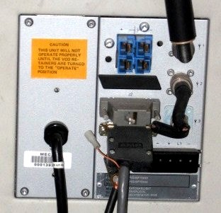
All of the station's input and output signals connect through this panel located on the right side of the cabinet. You will also find the model and serial numbers here:
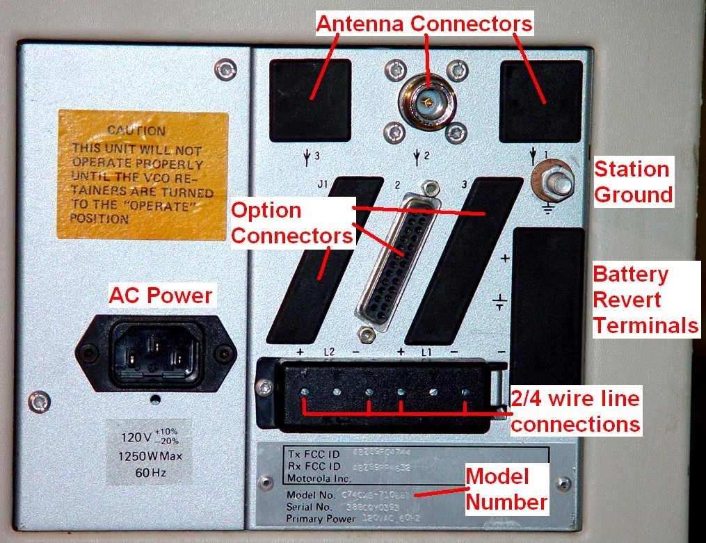

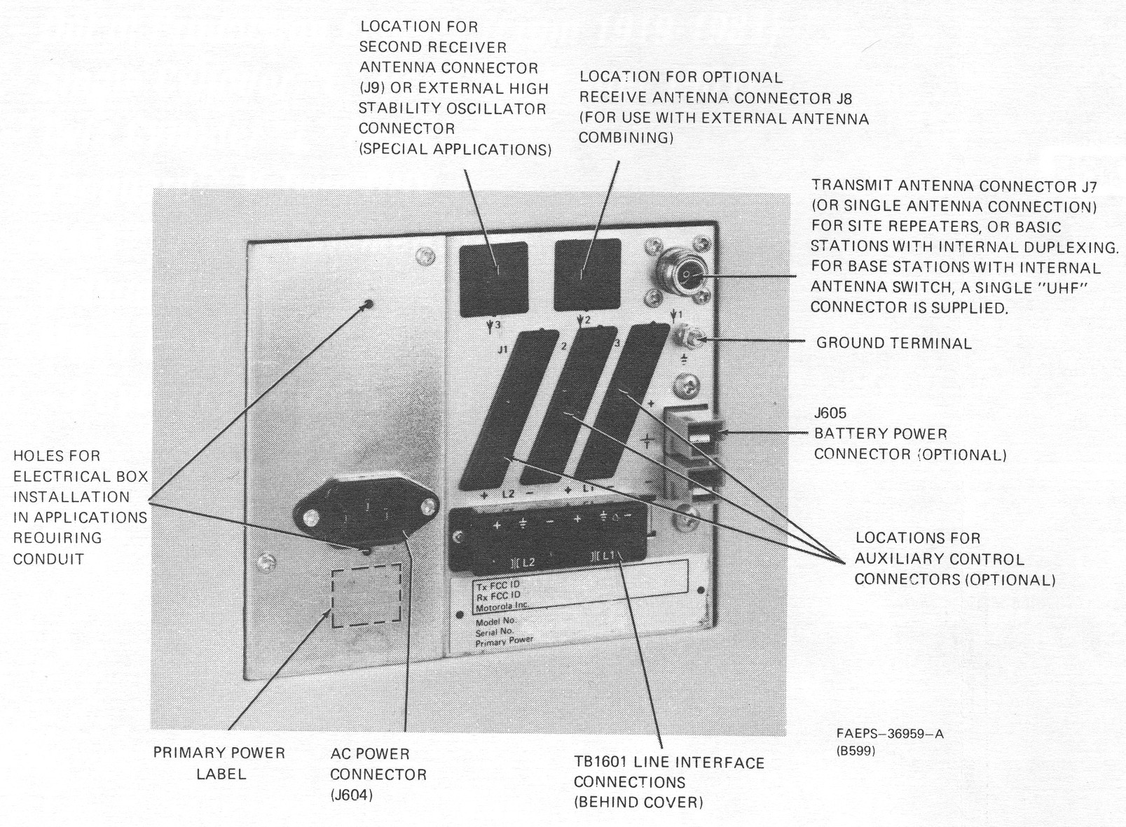
The photo above is from my system; the scanned images are from a Motorola manual.
The ground bolt is Metric 6x1.0 thread. Use a 1/4 inch external tooth lock-washer if you can't find a 6mm part.
There are three holes for RF connections. Motorola uses a single female UHF connector on UHF base stations, located in the right hole, and a single female N connector on UHF repeater stations, located in the center hole. An additional connector for split receive/transmit operation would be inserted in the left hole. On some repeaters, an optional high accuracy reference signal could be fed into a jack in the right hole.
Optional battery backup terminals are located along the top or right edge of the panel. Units without the option have a plastic plug in the hole, as shown. VHF stations higher than 25 watts will have three terminals: +28V, +14V, and Ground as seen in this photo:
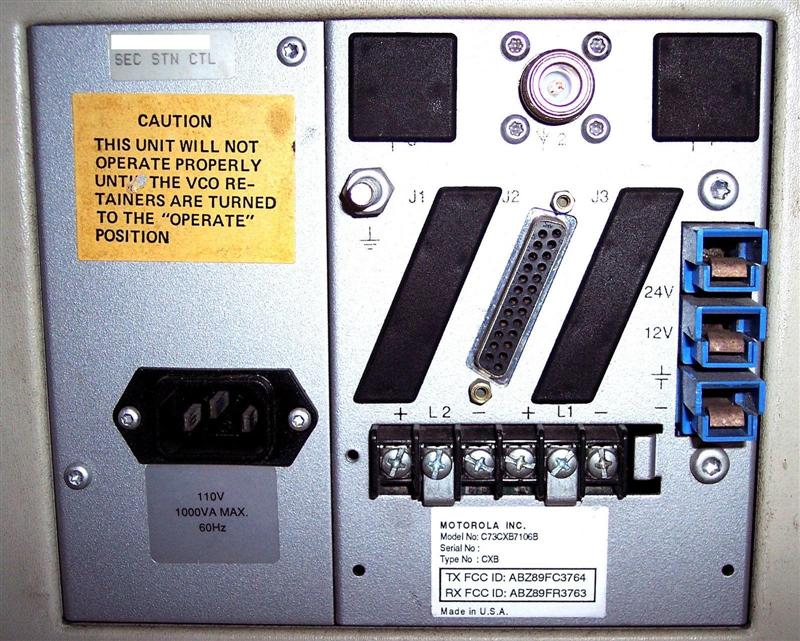
All other stations have two terminals: +14V and Ground, as seen two photos above. High-power stations (those with two power supplies) will have two pairs of battery terminals, as seen in this photo:
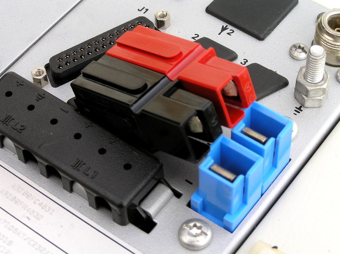
These are AMP Power Lock Series II connectors, rated for 75 amps. They are compatible with Anderson Standard Powerpole PP75 connectors. A Motorola battery cable is 3 meters long, uses #8 AWG wire, has 60A fuses in series with the positive leads, and is part number TRN5155. A similar cable (with a different type of connector) is available for the MTR2000 and MTR3000 stations but make sure the wire is large enough for the 14V MSF5000). The following table shows the part numbers for the connector sets:
| Component | AMP | Anderson |
|---|---|---|
| #6 Contact | 53880-4 * | 5900 |
| #8 Contact | 53880-4 * | 5952 |
| Blue Housing | 53884-1 | 5916 |
| Black Housing | 53884-3 | 5916G4 |
| Red Housing | 53884-4 | 5916G7 |
NOTE: The AMP contacts handle #6 through #10 wire, hence the same part number.
A complete set of the Anderson Powerpole connectors sells for about $8 and is shown here next to the station's battery terminals. Ed WØSD provided this photo.
Two-wire and four-wire remote control (tone or DC) wires are attached to the terminal strip along the bottom of the panel.
One or more DB25-style connectors are present in the middle, mainly for trunking or data use. On these stations, the other end of the cable plugs into the TTRC. The signals on these connectors are documented on other web pages at this site and in the manuals.
A standard IEC (computer) power connector accepts 120VAC to power the station. The 110w UHF repeater station draws 500 watts to produce 60 watts RF. Do NOT use a normal computer power cord for your MSF station when you finally put it in service; most of those are #16 gauge wire, and I've found a few that are #18. Find one that is #14 at least. The computer cords are OK for testing, however. High-power stations - C8X and C9X (those with two power supplies and two power amplifiers) - are usually directly hard-wired to the AC supply or have a permanently attached power cord, and do not have an IEC power socket. Also, the connectors are oriented differently. Here's the junction panel from a 150 watt 896 MHz trunking repeater. While not obvious in this photo, the upper N connector actually sticks out further from the panel than the lower N connector. This designates the transmitter output. Also note the BNC jack for the external 5 MHz or 10 MHz reference signal.

Inside the station, behind the junction box, is a 120VAC convenience outlet with a fuse underneath. This can be used to power test equipment, a soldering iron, etc. I plugged my PA fan into it (on the 26 inch cabinet). You can see it in the photo of the antenna relay above. They also provided threaded holes to mount a microphone clip, so you have a place to store the local test microphone.
I measured the AC input of my UHF 75w repeater station. Note that the power factor (PF) increases significantly when the station is transmitting. This is for 80 watts TX output.
| Condition | Volts | Amps | Watts | VA | PF |
|---|---|---|---|---|---|
| Idle | 121.6 | 0.70 | 60 | 86 | 0.70 |
| Transmitting | 120.5 | 3.36 | 378 | 405 | 0.92 |
Control Tray:
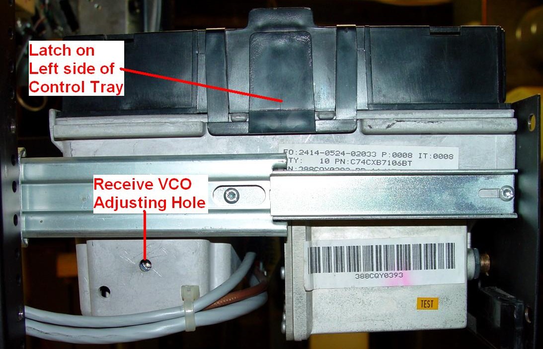
Everything in the MSF5000 was built to last - using cast aluminum and steel - except the control tray. The control tray is a plastic "after-thought" that sits atop the RF tray. A latch on the left side holds the tray in place; three plastic hinge pieces on the right side attach to pins at the top right edge of the RF tray casting. All of these plastic pieces can easily be broken, and they're all part of the molded tray. A slotted curved metal swing arm on the rear of the control tray limits movement to just slightly over 90 degrees. This is visible in the photo of the rear of the RF tray.
On digital-capable stations, the control tray holds the Secure-capable Station Control Board (SSCB), the Trunking Tone Remote Control board (TTRC), and a Secure (encryption) board (SEC). The SSCB controls the station; the TTRC is only present on those stations that need remote control; the SEC is only present on those stations that require it.
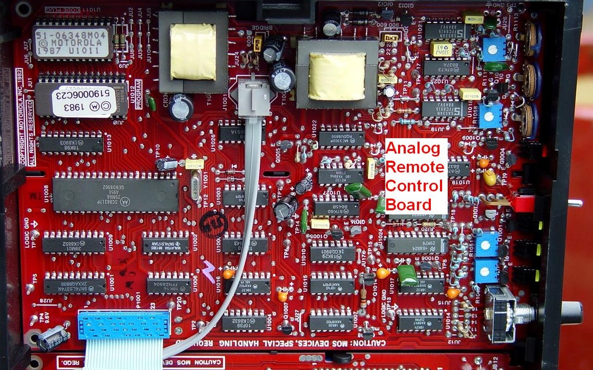
On analog stations, the control tray holds the Station Control Module (SCM) and some kind of remote control board, either tone, DC, or trunking. These units are functionally equivalent to the SSCB and TTRC.
There are several front panel switches and indicators on the control tray. The digital-capable stations have a three-digit LED display on the right side that can show error codes, current channel and mode, and other station parameters. Switches can disable the receiver's PL/DPL decoder, manually key the transmitter, set the channel, and access several internal parameters. Several status LEDs let you know the station is transmitting. There is no indication of any receive activity. The volume and squelch pots only affect what you hear on a headset or loudspeaker in the metering panel, i.e. the audio that comes out the control or expansion jacks. An intercom switch on the remote control board lets you talk to the control operator via the wire-line interface using a local microphone and metering panel, or handset.
The analog station has a series of adjustment pots along the front and several status LEDs. The knob on the remote control portion is used to manually select an operating channel.
A covered 40-pin connector sits on top of the control tray enclosure. This connector is used for an expansion chassis or metering panel. The front panel 6-pin Control jack accepts a microphone or handset.
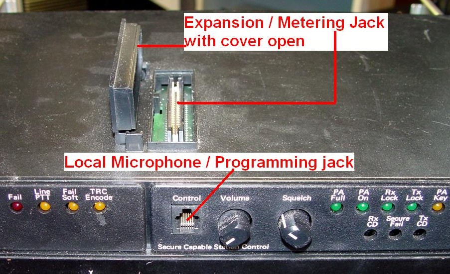
The digital-capable stations use software, a Radio Interface Box (RIB), and serial cables for programming. Radio interface cables can be made to plug into either the 6-pin control jack on the front, or the 40-pin expansion jack on top of the control tray. Cable information is available elsewhere on the web.
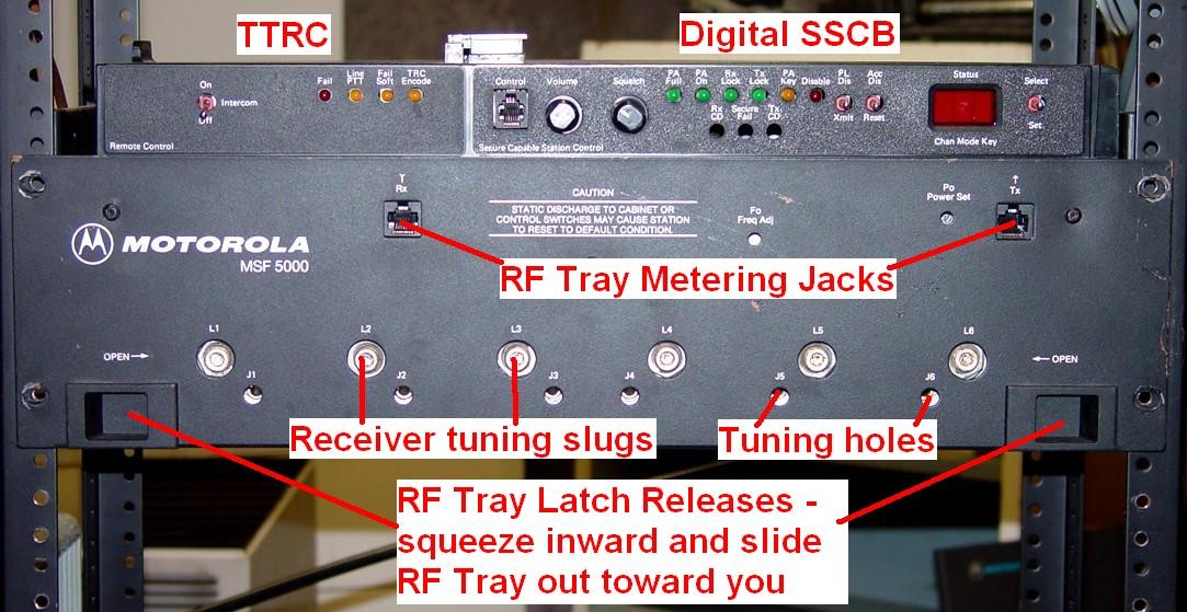
RF Tray:
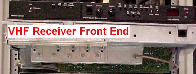
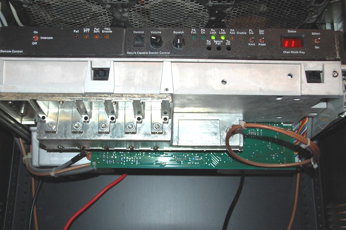
The RF tray contains several modules inside the cast aluminum body. The receiver front end (tunable pre-selector) hangs down under the front of the RF tray and is covered by the front panel. Tuning slugs are accessible through holes in the panel, but the panel must be removed to access them on VHF stations:
Here's a photo, courtesy of Mark W1ACP, of the front of a VHF station:
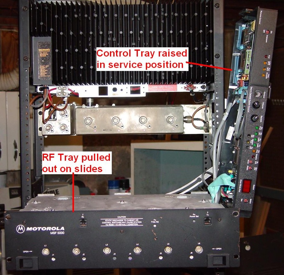
You must slide the RF tray out of the cabinet to access anything inside it. Remove any large Torx screws at the sides of the front panel holding it to the frame, then squeeze both latches towards the center and pull the RF tray assembly straight out. It will slide completely out of the frame, and you can then swing the control tray up into its service position. It will just clear the power amplifier's heat sink when the RF tray is fully extended.
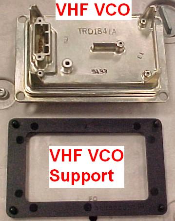
Once the control tray is lifted to its service position, you will find two metal knobs that turn cams under the RF tray's cover. These push the VCOs in their cavities to lock them when the station is being moved. When unlocked, the VCOs rest on springs to minimize noise pickup. The station will work with the VCOs in either the locked and unlocked position, but performance is only guaranteed when unlocked, and the station will pick up any vibrations from other equipment, such as fans, which will generate microphonics. The VCOs need to be in their locked position to gain access to the tuning slugs. However, VHF VCOs are not adjustable and do not have the tuning slug. Note that this shipping lock has nothing to do with the VCO Lock LEDs on the front of the control tray. Here are both knobs when locked locked:

and unlocked:

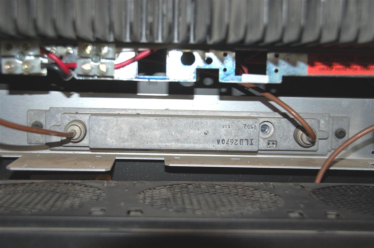
If you look real carefully along the left front edge of the casting, you'll see a little yellow sticker with the assembly part number. The last digit - 2 - signifies a Range-2 station.
The receive VCO is located in the left rear of the RF tray. Here's a photo of that side showing the VCO tuning slug adjustment hole (the VCO is locked down):
Notice the yellow sticker on the Receiver Front End assembly, to the left of the SMA antenna connector. The last digit - 2 - signifies a Range-2 station.
The bundle of cables consists of the RF tray IPA output (coax), power amplifier metering (small gray cable), and power into the RF tray (large gray cable).
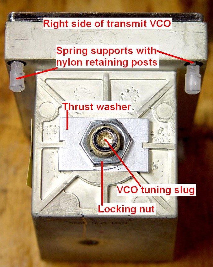
The transmit VCO is located in the right rear of the RF tray. Here's a photo of that side showing the VCO tuning slug adjustment hole (the VCO is locked down):
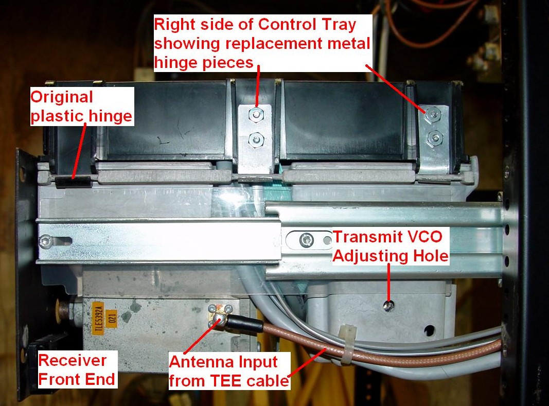
The bundle of cables consists of the receiver input (coax), wire-line connections on the junction box (two small flat cables), and the DB25 options connector on the junction box (large gray cable). Also you can see two metal replacement hinge pieces that broke off the plastic control tray.
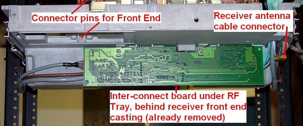
Underneath the RF tray, behind the receiver pre-selector but in front of the VCO wells, is the interconnection board. This receives power from the power supply and sends it to the RF tray boards and the control tray. This is what it looks like from the back. You can only see this if the outer cabinet has been removed. Also visible in this shot is the swing arm that limits travel of the control tray:
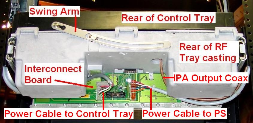
The extra connector along the bottom edge is for a second receiver, in its own RF tray, that can be added to the MSF5000 stations. I've never seen one, but the RSS does allow for it. The tray would have everything except a transmit VCO.
Reference Oscillator:
The 896 MHz stations typically have one more chassis at the very bottom of the cabinet; this contains a 14.4 MHz reference oscillator for the RF tray and an optional High-Stability (ovenized) 5 MHz or 10 MHz Oscillator (HSO). These stations will also have an additional RF connector (BNC female) on the station junction panel for an external frequency source or to slave other stations to one master oscillator. Only one reference oscillator at a site needs the HSO; the rest get daisy-chained to it. Here's a front view. This photo was supplied by Roger W5RD:

Here's what's inside. The 14.4 MHz oscillator, dividers, and power supplies are located in the box on the right. The anodized box on the left is a 5 MHz HSO, which lists for over $1000. Not all units have the 5 MHz oscillator; those that don't require an external source which can be 0.1, 1, 5, or 10 MHz, selectable via internal jumpers. Roger W5RD supplied this photo.

Taking Apart the Control Tray:
We've seen all of the major assemblies; now it's time to dig deeper.
Secure-capable (Digital) Control Tray:
After sliding the RF tray out, release the latch on the left side of the control tray and swing the tray up on its hinges on the right side. There isn't much that's serviceable underneath; I find it easier to completely unplug the control tray and remove it from the RF tray. The swing arm on the rear can be unhooked from the stud on the back of the tray by squeezing it so the slot fits over a smaller shoulder, then sliding the arm a bit. Anyway, here's what it looks like in the service position:
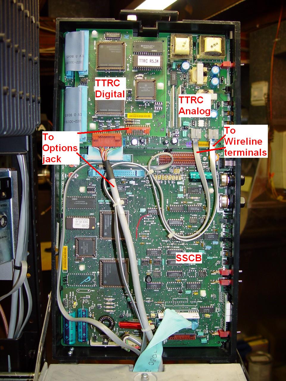
Here's a shot of two of the boards inside the control tray:
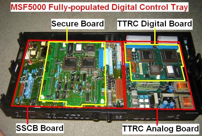
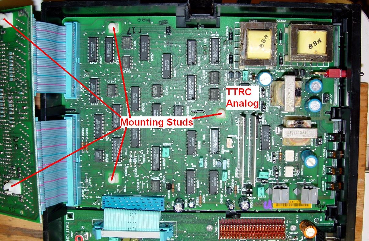
A third board, the secure (SEC) module, mounts to the SSCB. Here's a photo (found on the web) of a fully populated late-revision control tray; I've identified the circuit boards. The secure module on this tray doesn't have the sockets for the encryption hybrid modules.
Here's another photo of an earlier-revision control tray I ran across, with the boards outlined and identified. This one does have the hybrid module sockets.
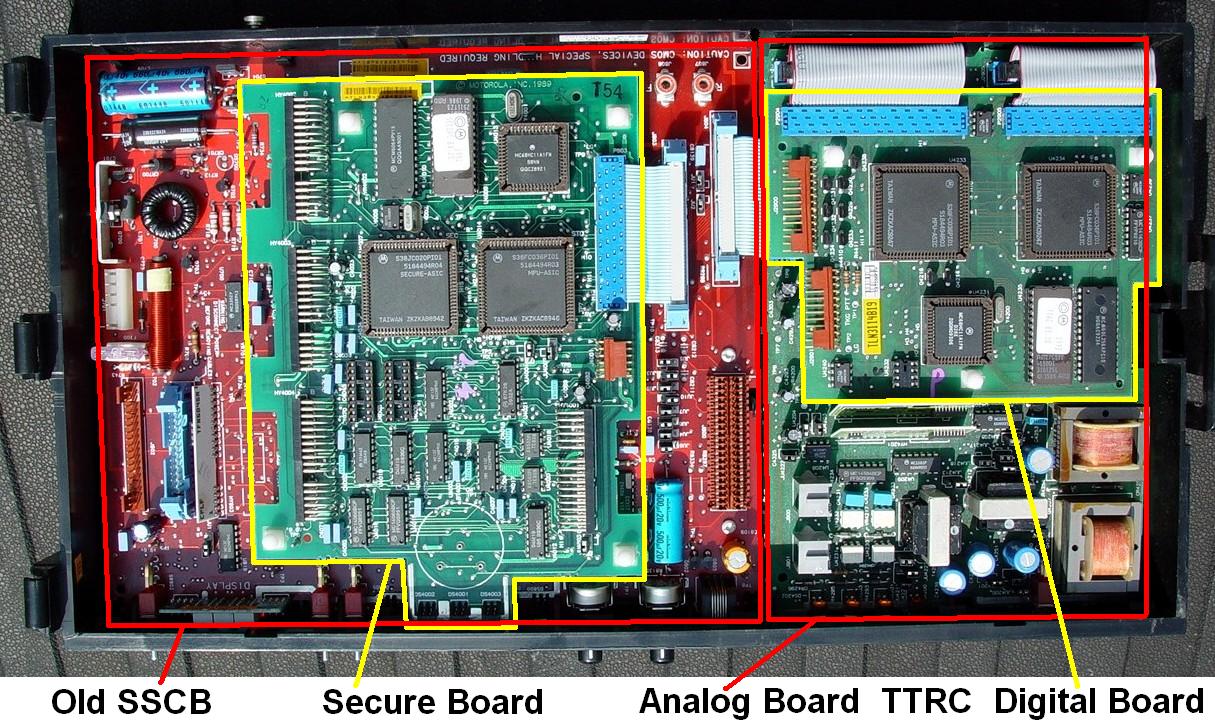
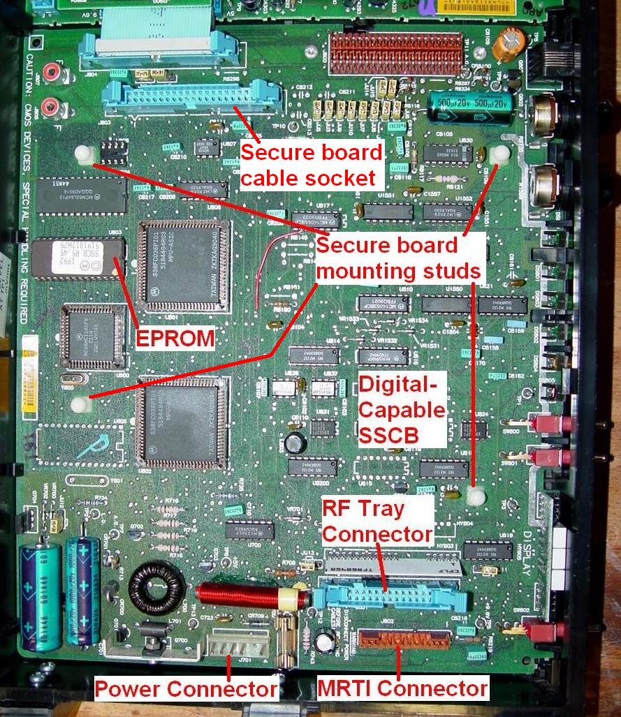
The Secure-capable Station Control Board (SSCB) controls the station. All adjustments are maintained via 100-position, digitally controlled, non-volatile Electronically Erasable Potentiometers or EEPots (Intersil X9312UPI or equivalent), which can be set via RSS or the front panel. The firmware EPROM is the only replaceable component. Several options jumpers are present; these are detailed in the instruction manual.
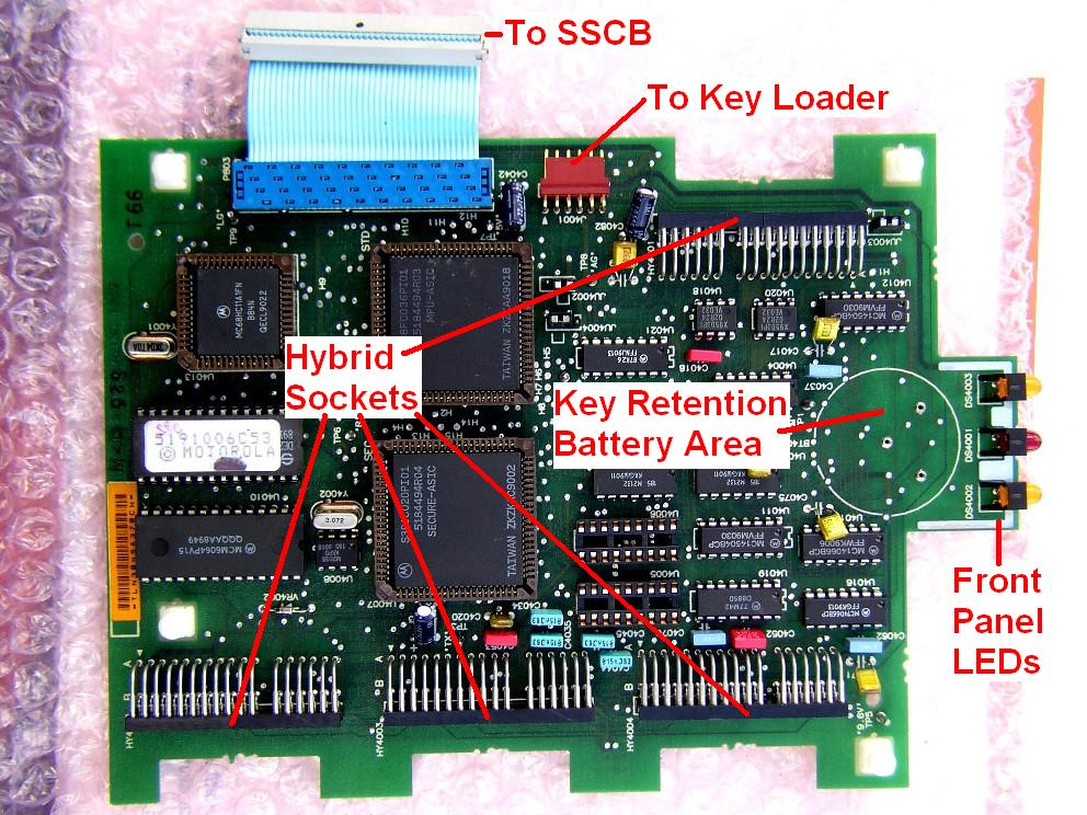
A secure (encryption) board snaps onto posts on the SSCB. Amateur repeaters probably wouldn't use one, but I've included it for completeness. The three LEDs on the SEC board fit into holes on the front panel; you can see these empty holes on the front panel photos if you check them carefully. The photos below show some of the identifiable items on the board. There's an area for a plug-in lithium battery to maintain the security key information. A key-loader cable plugs into the 6-pin connector. Sockets on the board hold the secure algorithm hybrid modules. There are apparently two ways to configure secure boards: full encryption and transparent. Both boards will allow repeating of secure (digital) communications. The full encryption board would have sockets and hybrid modules and the battery so it can encrypt plain audio and decrypt secure audio. The transparent board doesn't have these components. Bernie KH6IAH supplied this full-size photo of a secure board:
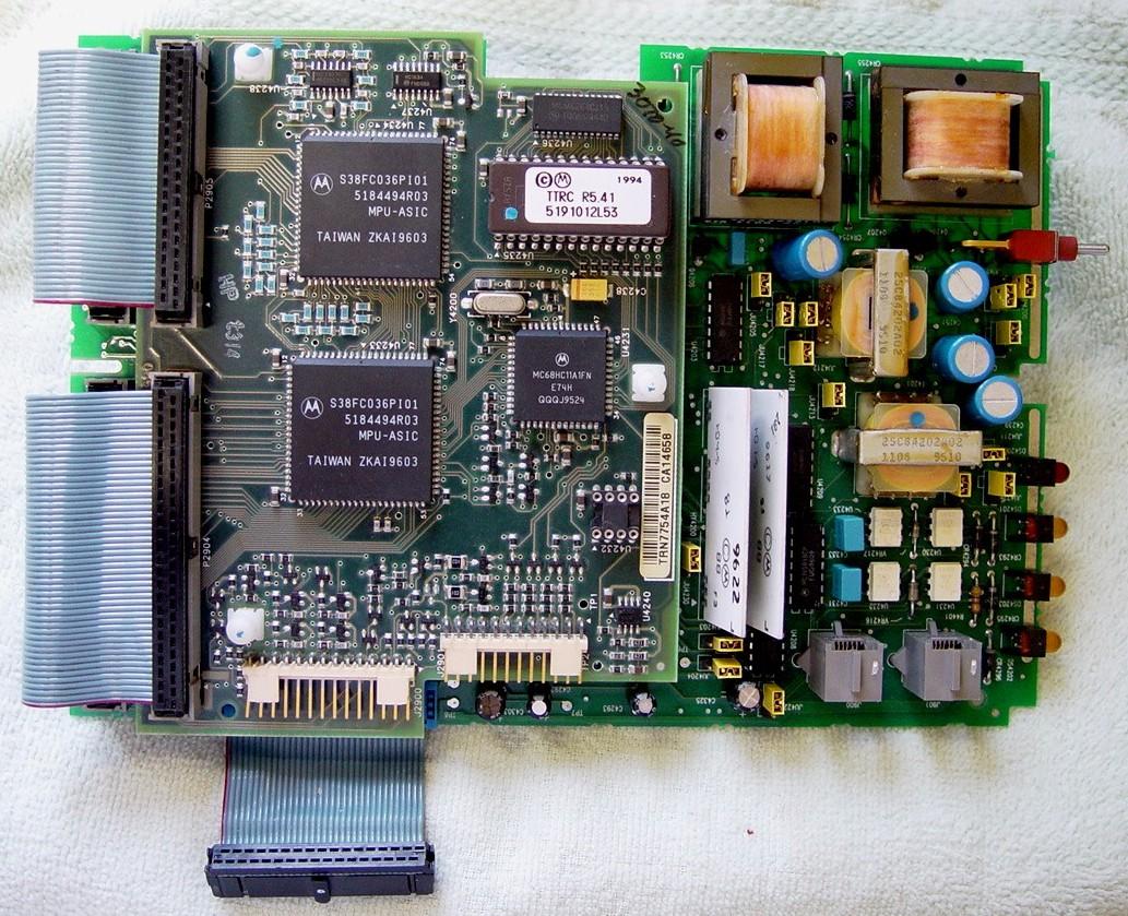
The Trunked Tone Remote Control (TTRC) boards handle tone and DC remote control of the station, as well as trunked control. Two- or four-wire line control is possible. Various tone and DC current values are configured via the RSS. The TTRC consists of two circuit boards: a digital board that has the microprocessor and firmware on it, and an analog board that handles the wire-line interface. The digital board snaps onto posts on the analog board. Note that on this board, the three big ICs are in sockets, there are lots of parts on the back of the board, and the two flat ribbon cables at the left are permanently attached to it.
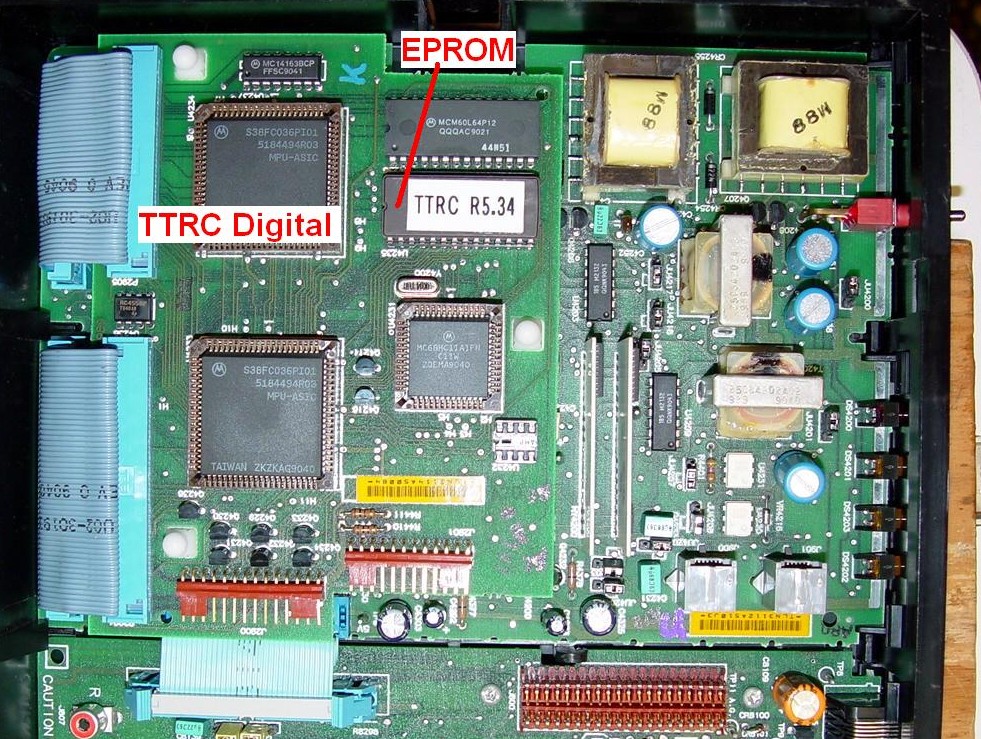
A newer-style TTRC digital circuit board has a lot more surface-mount components (there are no parts on the back of the board), the big ICs are soldered to the board, and short removable jumper cables are used to connect the digital board to the analog board underneath it. These boards are fully interchangeable.
The analog board is underneath the digital board. Both boards are required:
The two modular jacks on the TTRC analog board are for the wire line terminals on the station junction panel. The front-most jack (J901) is for the LINE3/LINE4 pair; the jack closer to the center of the board (J900) is for the LINE1/LINE2 pair. If your station only has one RJ11 flat wire in the cable bundle, it would be for LINE1/LINE2 and would plug into the jack closer to the digital board in these photos. Neither RJ11 plug nor socket is identified so you won't know which plug goes into which socket (thanks, Motorola).
Analog Control Tray:
The analog control tray can also be tilted up to the service position. Since these stations are not capable of digital transmission, no secure (encryption) board is available.
The Station Control Module (SCM) is equivalent to the SSCB. It controls the station. Several pots may be accessed through holes in the front panel. These set squelch and audio levels. There is a firmware EPROM and a code plug EPROM. The code plug data (EPROM) must be programmed using an R1801 suitcase programmer equipped with the proper firmware and EPROM adapter. The firmware PROM (U804) in the non-trunked CLB stations is a 2764 family chip and is No Longer Available (NLA) from Motorola. The code plug (U803) is a 2732 family chip. The 2732 (plain, non-A-chip) needs 21 volts for programming while the 2732A needs just 12.5 volts. Motorola had different plug-in adapters for the R1801 suitcase programmer for these chips. A toggle switch was often added to the adapter to select the appropriate programming voltage so one adapter could do both the 2732 and the 2732A EPROMs. If your station has had both EPROMs removed (which is commonly done to government surplus equipment for security reasons), you'll have to find another CLB station and burn a copy of U804 in that. (I haven't checked, but some of the people that can program code plug EPROMs may be able to supply a firmware EPROM. Contact information is on the main MSF index page.)

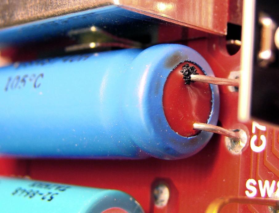
Several large electrolytic capacitors are present on the SCM. One in particular is very critical to proper station operation: C706, located in the lower right corner. This should be replaced as soon as you get the station as it can cause all sorts of strange and unrelated problems. It has three leads: two at the top (red) end (the actual working leads) and one at the bottom end which just holds the capacitor body to the circuit board. The photo below shows a bad C706 with electrolyte oozing out around the positive lead. Gary AGØN supplied this photo.
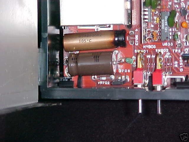
Here's a photo of another C706 that's obviously seen better days:
You can replace it with a radial-lead capacitor and secure it to the board with some double-sided tape or a dab of glue or silicone sealant. There's also a small chip capacitor underneath the board soldered across the two leads of C706, so be careful when you replace the cap (the solder is the only thing holding the chip cap in place). New electrolytic caps will probably be smaller than the original ones. The following list shows the capacitor designations, values, and the circuit they're used in:
| Ref# | Value uF | Circuit Used In |
|---|---|---|
| C702 | 660@40V | 5V Power Supply |
| C706 | 1000@12V | 5V Power Supply |
| C838 | 220@25V | Speaker Audio Amp |
| C840 | 500@20V | Speaker Audio Amp |
| C842 | 220@25V | Speaker Audio Amp |
| C851 | 100@16V | 5.1V Reference |
The Tone Remote Control (TRC) board is equivalent to the TTRC. It allows two- or four-wire line control of the station. The channel switch on the front allows manual channel selection. There is a firmware EPROM and a code plug EPROM on this board as well. There is also a DC current remote control board as well as a trunking controller board, but only one board fits into the control tray at a time. All of this functionality is built into the digital-capable station's TTRC.
Control Tray Board Removal:
Since everything in and on the control tray is plastic, it's fairly easy to remove things. It's also fairly easy to break the thin plastic tabs holding pieces in place.
The front panel escutcheons (TTRC or TRC, SSCB or SCM) are held in place with tabs. If the control tray is in the service position, these tabs are on the inside bottom edge, closest to the RF tray. These can be pushed downward slightly while pushing the front panel outward. Hooks on the top edge of the escutcheon can now clear the frame behind the panels. After disconnecting any cables, the modules can be pulled slightly forward into the frame openings so the circuit boards clear tabs at the rear of the control tray. These tabs at the rear, plus the front panel escutcheons, are all that hold the modules in place.
The control tray frame itself is probably the same for both the analog and digital-capable stations. The boards and front panel escutcheons are different, of course.
Expansion Chassis:
While not really part of the control tray, this is as good a place as any to mention this optional assembly. Additional electronic modules can be added to the MSF5000 station, but since the control tray is full, Motorola came up with a piggyback expansion tray. This plugs into the expansion jack on top of the control tray and attaches to the control tray. Another expansion jack on top of the expansion tray allows access to the now-occupied jack (on the control tray) for metering or programming. Since the top of the expansion tray is hinged at the rear, I doubt anything else can be mounted on top of it.
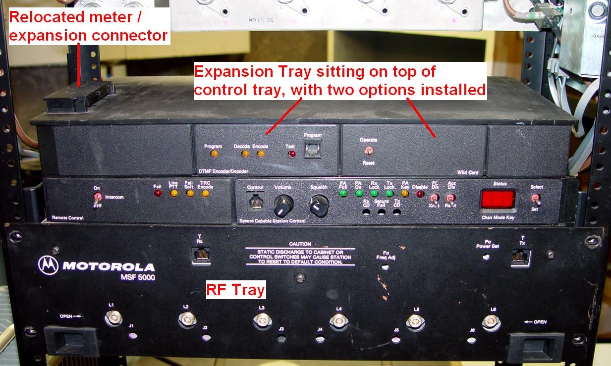
Besides a power supply regulator/filter, two modules are in this particular expansion tray: a wildcard module and a DTMF module. The wildcard module can be programmed and jumpered to do all sorts of things based on internal control tray signals, but without documentation, it's nearly impossible to utilize. The DTMF module can be set to recognize DTMF tones and perform functions based on the digits heard. Both analog and digital-capable stations can work with an expansion tray. A Station Access Module (SAM) can also fit inside the expansion tray. This board can encode and decode various tone signaling schemes and control station functions like repeater setup and knockdown, changes in frequency and operating parameters, etc. It is extremely complex. I've never seen one. The RSS programs all its functions.

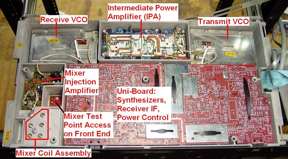
The final major assembly to be looked at is the RF tray. This one unit is basically the receiver and exciter of the whole station. The top cover is easily removed after first putting the control tray into the service position. You can see all of the modules:
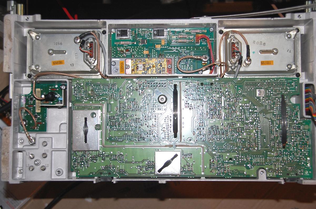
The VHF station is similar. Here's a photo of one taken by Bob VE3DJ:
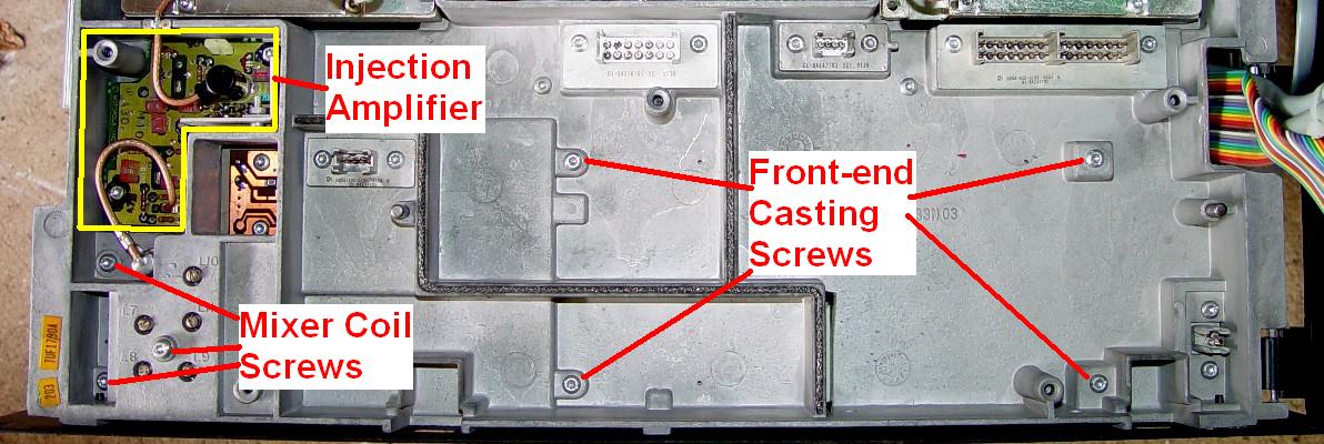
Working from the upper right and moving left, you see the transmit VCO, the intermediate power amplifier (IPA) which also has the station's 9.6V regulator on it, the receive VCO, and the mixer injection amplifier. The mixer injection amp gets its power through the insulated RCA plug and coaxial cable. To reduce receiver inter-modulation distortion, the mixer's local oscillator signal comes out at nearly one watt. The last item is the mixer coil assembly, which plugs into the receiver front end (pre-selector), which is mounted under the front of the RF tray casting.
The IPA feeds the power amplifier. On VHF stations, it is capable of 8 watts. On UHF stations, it can generate 9 watts. On 800 and 896 MHz stations, it generates only 4 watts. Typical output power of 2-4 watts is all that's required to have the power amplifier generate rated power. On the older IPA modules where a ceramic circuit board occupies most of the space (like in the photo of the RF Tray shown previously), the IPA output is a permanently attached length of coax with an N-male connector at the far end. This coaxial cable connects the IPA to the Driver PA, PA, or internal filter/duplexer. On the IPA modules that have a small RF brick in one corner (like in the photo below), the IPA output is an SMA jack under the RF tray casting that the coax cable attaches to. Here's a photo of a VHF IPA/Regulator assembly supplied by Bob VE3DJ:
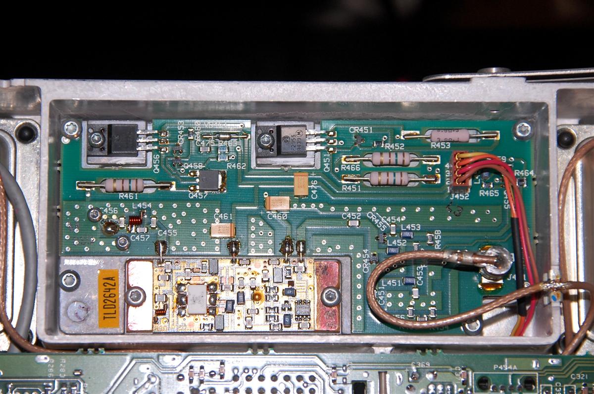
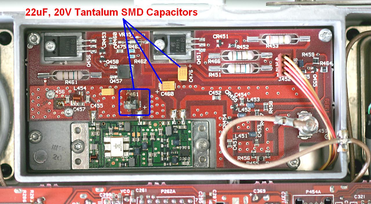
A common problem on some IPA boards is the sudden and fatal destruction of a 22uF, 20V tantalum capacitor. In the photo below (from a VHF station), C461 has vaporized. Sometimes the shorted cap also takes out the foil on its right side. There are three such capacitors on the board, but not all versions have them. Some older-style IPA boards use discrete circuitry on a ceramic substrate (as seen in the photo above) rather than the "RF Brick" module used here. Tim W5FN supplied this photo.
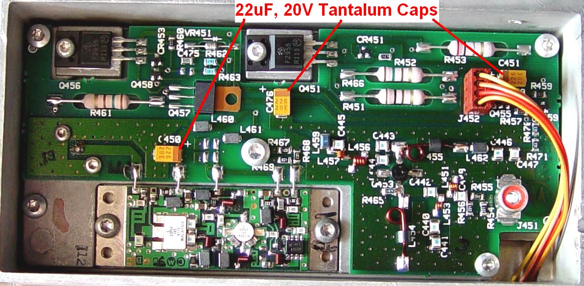
The same troublesome capacitors (that have not yet shorted) are shown on this photo of an 896 MHz IPA board.
When one of these caps shorts out, it often causes a trace on the Uniboard to burn up as well, so after replacing the caps (use 22uF 35V caps), check for continuity between the A+ line coming into the Uniboard: at P402A pins 2 and 3, over to where the IPA/REG board cable plugs into the Uniboard: at P454A pin 3. Run an insulated wire jumper over the burnt foil if necessary. More information on repairing the IPA/REG board, including a PDF file that shows the Uniboard trace that gets burnt, can be found in the Replacing IPA Caps article that can be found on this web site.
Circuit Boards:
The main board is called the Uniboard. It has the receiver IF, receiver synthesizer, transmitter synthesizer, transmitter power control, and reference oscillator circuitry (for VHF and UHF stations). It just unplugs from the RF tray casting connectors. You can also unplug all of the cables attached to it for total removal. Here's the component side:

The transmit VCO feeds the IPA which feeds the power amplifier. The receive VCO feeds the mixer injection amplifier which feeds the mixer in the front-end assembly. The IPA and mixer injection amplifier are screwed into the RF tray casting but can easily be removed. Be careful when handling the thin ceramic substrate on some modules. The IPA puts out between 3 and 9 watts; this controls the output power of the station.
The VCOs:
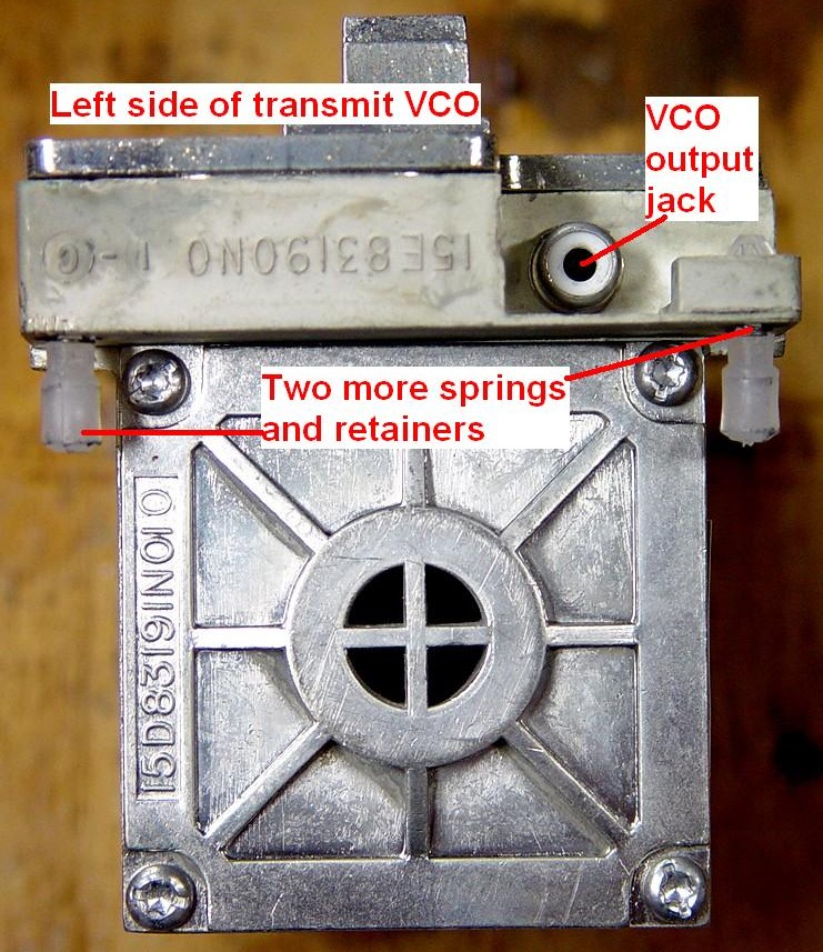
The VCOs (Voltage Controlled Oscillators) are the main frequency generating elements in the station. These are controlled by the synthesizer circuitry on the Uniboard, which is controlled by code plug data in the station control board in the control tray. Since the station is capable of full-duplex operation, two independent VCOs are necessary. They are identical except that the transmit VCO has a modulation input and a few more components to couple audio to the actual oscillator. Each one puts out about 10mW. For testing purposes, a transmit VCO can be used as a receive VCO, but not the other way around. The raised tab on top is what the VCO locking cam pushes against when in the transit position. The VCO electronics are on a circuit board under the top cover. Here's a close-up of the VCO:

The VHF VCO is similar but it is not externally tunable. Here's a photo of the top of a VHF TX VCO supplied by Bob VE3DJ:
The end of the VCO that faces the outside of the RF tray casting (right side for TX, left side for RX) has the tuning slug in it. When the VCO is locked in the transit position, the 5mm hex opening in the tuning slug lines up with the hole in the side of the RF tray casting. Note that the VHF VCOs are not adjustable and do not have the tuning slug.
The VCO tuning should be smooth. The M5 meter indication should not jump nor drift as you adjust the VCO tuning slugs. If you encounter difficulties, remove the VCO, remove the tuning slug, clean it thoroughly, pull the other end off the VCO and remove any loose metal particles from inside the VCO cavity, re-assemble, re-install, and retune. This problem is not specific to Motorola; it happens to GE equipment as well. See this article for further information.
Nothing special except some ventilation holes on the other end:
The VHF VCO is similar but it is not externally tunable. Here's a photo of the top of a VHF RX VCO supplied by Bob VE3DJ:

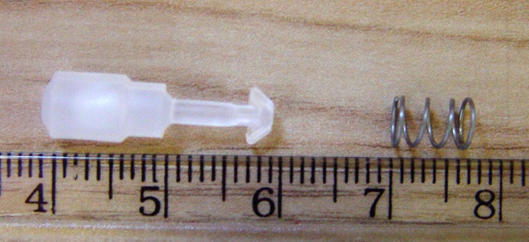
Each VCO is supported by small springs in each corner that are held in place with plastic captive spring retainer pins that fit into holes in the RF casting. When the plastic pins get old and break, the VCO sits on the casting and is susceptible to vibration, which can generate noise in the receiver and transmitter. The spring retainers, p/n 4283517N01, were $2.50 each and eight are required. The springs, p/n 4183147N02, were $3.00 for a bag of 10. Here's what new ones look like:
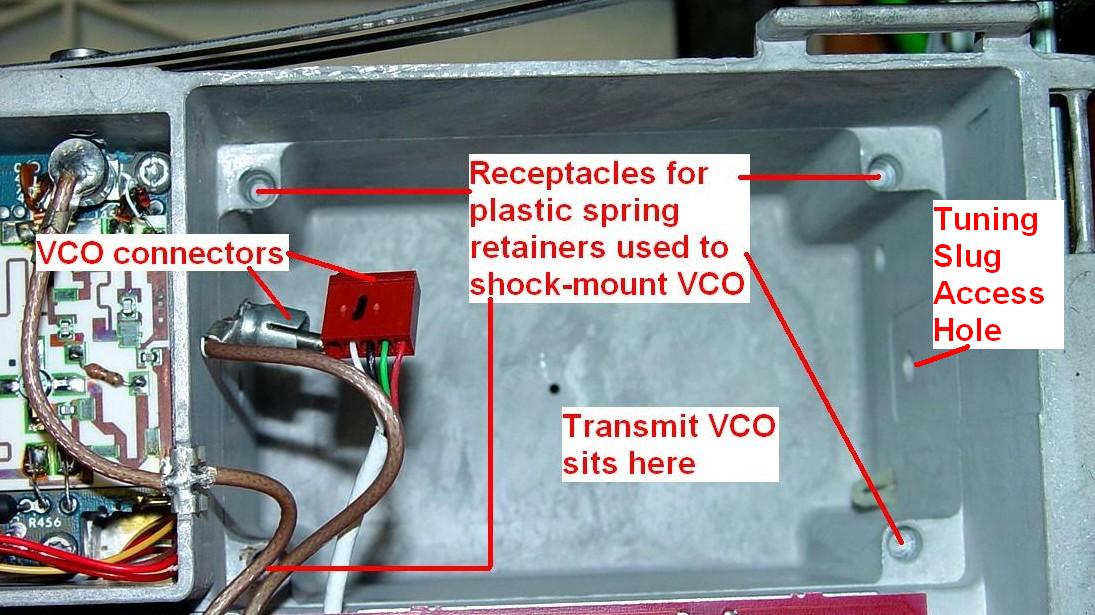
Here's a look into the transmit VCO well. The plastic pins sit in the four holes in the corners:
The VHF stations do things differently. The VCO doesn't have the springs and plastic pins. Instead a plastic ring sits inside the casting and four pins fit into the holes in the corners of the RF casting. The VCO then sits on four pins on top of this ring. This limits how far the VCO can move. The locking cams may be hard to actuate on VHF stations. Here's a photo, courtesy of Mark W1ACP, of the VCO and the plastic support ring:
Receiver Front End (Pre-Selector):
The front end is a separate casting that mounts underneath the RF tray casting.

RF enters via the SMA connector at the right side; this cable comes from the antenna T/R relay or duplex TEE cable. Each of these six tuned circuits provides about 15dB of rejection of signals 5 MHz away from the tuned frequency on UHF stations.
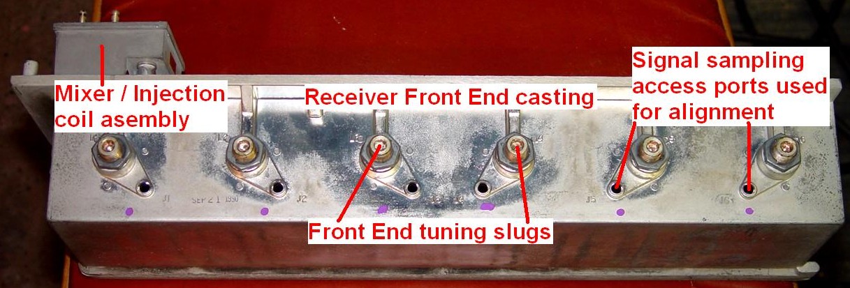
The VHF stations do things differently. There are only five sections to the front-end casting. The tuning slugs do not protrude through the RF Tray's front panel but are recessed behind it. Being smaller, there are fewer screws holding it to the RF Tray. The picture below, courtesy of Mark W1ACP, shows the VHF front end assembly after the front panel has been removed:
The picture below, courtesy of Bob VE3DJ, shows the entire VHF front end casting. The tuning slugs and tuning holes are clearly visible. The RF Input coax connects to a mini-UHF jack at the front right face of the assembly.
To remove the front end casting, unplug the Uniboard and fold it up and out of the way towards the back of the RF tray. Unplug the mixer injection amplifier's output coax (black RCA) plug from the mixer coil assembly. Remove the RF input coax SMA connector from the right side of the front-end casting. Remove the screw in the middle of the mixer coil assembly. Remove the six front-most Torx screws going down through the RF tray casting into the front-end casting, probably fewer for the VHF station. All of these screws are shown in the photo below. Support the front-end casting as you do this; it's heavy and nothing else is holding it in. The mixer coil assembly comes out with the front-end casting.
When the front end is removed, you gain access to the mixer coil assembly and the circuit board with the mixer and 15dB RF preamp on it:
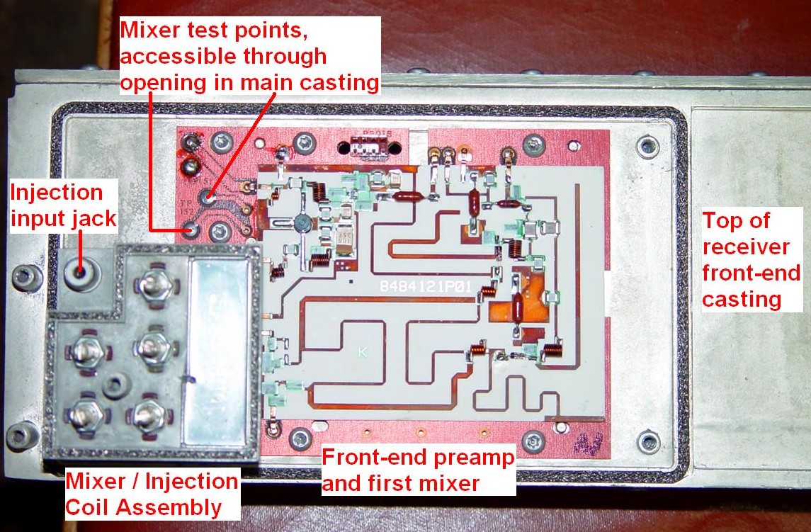
The mixer coil assembly just plugs into the circuit board via three RCA connectors and can easily be unplugged:

The VHF mixer injection amplifier and filters are similar. Here's a photo of the top that assembly supplied by Bob VE3DJ:

Behind the front end casting is the RF tray interconnection board. A view from the rear of the RF tray was seen earlier; here it is from the front.
Two screws hold the interconnection board to the casting. Unplug all of the cables as you remove the board; there's not much slack and quite a congestion area at the right side. There will be a DC input cable from the power supply, a DC output cable going to the Control Tray, a flat cable going to the Control Tray, one cable going to the 6-pin Molex cable attached to the PA (two cables - Driver PA and Final PA - on high-power stations), an antenna relay cable (for base stations), and a High Stability Reference Oscillator power cable (for 896 MHz stations). This board contains a 5V regulator that powers some of the circuitry on the Uniboard (digital-capable and analog-plus stations only).
When reassembling the RF tray, take great care to line up all the connectors before fully seating the front end or the Uniboard. They are not necessarily self-aligning and pins can easily be bent and broken off. Like all Motorola equipment that's more than 10 years old, most parts are no longer available.
All of those feed-through connectors can be removed from the casting; you might want to remove them before reinstalling the assemblies from underneath, then reinstall the connector blocks after the major assemblies are secured in place. Treat these gently; the dual 14-pin connector block that the Uniboard plugs into retails for $250US.
Front Panel Indicators and Controls:
Digital Front Panel Indicators:
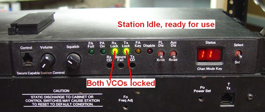
The digital-capable (CXB, RLB, GFB) stations go through a lot of self-tests at start-up. All of the LEDs on the TTRC will light up when power is first applied; they'll turn off one at a time as the self-tests progress. The red Disable LED on the SSCB will also be lit during testing. When complete, you should have two green LEDs lit: Rx Lock and Tx Lock. These indicate the respective VCOs and synthesizers are working properly. The 3-digit LED display will show the current channel and mode, and if a secure board is present, a third digit will show the key in use. All other LEDs should be off. Here's a typical turn-on display sequence from a station with an SSCB and TTRC (no secure board). The firmware revisions may be different on your station. Each step will remain on the display for a couple of seconds:
| Display | Meaning |
|---|---|
| 8.8.8. | Lamp test - all segments on |
| - - - | Performing tests |
| 5.4 5 | SSCB Firmware Revision |
| - - - | Performing tests |
| 5.3 4 | TTRC Firmware Revision [1] |
| - - - | Performing tests |
| x.y z | SEC Firmware Revision [2] |
| 1 1 n | Channel Mode Key [3] |
| . . . | Idle Display [4] |
Notes:
[1]: If there is no TTRC installed, no TTRC Firmware Revision is displayed.
[2]: If there is no SEC installed, no SEC Firmware Revision is displayed.
[3]: When a secure board is present, a third digit "n" representing the "key" shows
up.
[4]: Older SSCB firmware revisions may just show a blank display.
Error codes will be displayed as they are detected. Consult the instruction manual for a complete list; the RSS also has these listed in a help screen. When the station passes all the tests and is ready for use, the panel looks like this:
When the station is transmitting, all the other LEDs on the SSCB (except Disable) will light up. Note that PA Key means the transmitter is being told to key up, PA On means some RF power is being produced, and PA Full means at least 50% of the expected output power is coming out.
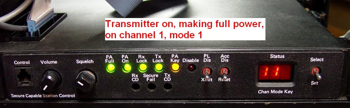
The Disable LED will turn on when the station's Acc Dis switch is set. This prevents the transmitter from turning on.
Digital Front Panel Controls:
The TTRC has an Intercom On/Off switch that will allow a technician to talk back to a console via the wire-line interface. This switch is also used to disable fail-soft operation on a trunking station.
The SSCB has a Volume control for the loudspeaker (contained in the metering panel).
A Squelch control adjusts the squelch setting when the station's Acc Dis and PL Dis switches are set.
To the right of the LEDs are two station control switches. Depress the first one (Xmit) to cause the transmitter to key up, but all audio is suppressed. Raising the first one (PL Dis) disables receive PL/DPL and puts the receiver in carrier squelch. Depressing the second switch (Reset) causes all of the display segments to turn on (lamp test) and performs a complete station reset, just as if power had been removed and reapplied. Raising the second switch (Acc Dis) disables all station access, allows selection of the tuning channel, freezes any analog diagnostics, and activates the front panel Squelch control. Raising either switch illuminates the Disable LED.
The switch to the right of the channel/mode/key display is a momentary switch that is used for various functions, such as manually setting the channel or mode, setting the EEPots, etc.
Analog Front Panel Indicators:
The analog (CLB) stations will also illuminate the respective Rx Lock Tx LEDs when the station is idle. The PA Full, PA On, and PA Key LEDs will light in transmit and they have the same meanings as on the digital station.
The Disable LED will turn on when the station's Acc Dis switch is set. This prevents the transmitter from turning on.
The Test LED will blink 1, 2, 3, or 4 times if an error is detected during power-up. Consult the Error Codes documentation found in the MSF&PURC section.
Analog Front Panel Controls:
The TRC has an Intercom On/Off switch that will allow a technician to talk back to a console via the wire-line interface. This switch is also used to disable fail-soft operation on a trunking station.
A channel selector switch allows manual channel selection when the SCM's Acc Dis switch is set. On the DC remote control board, you can only choose channels 1 through 4.
The SCM has a Volume control for the loudspeaker (contained in the metering panel).
A Squelch control adjusts the squelch setting when the station's Acc Dis and PL Dis switches are set.
To the right of the LEDs are two station control switches. Depress the first one (Xmit) to cause the transmitter to key up, but all audio is suppressed. Raising the first one (PL Dis) disables receive PL/DPL and puts the receiver in carrier squelch. Depressing the second switch (Test) performs a limited diagnostic and station reset, just as if power had been removed and reapplied. Raising the second switch (Acc Dis) disables all station access. Raising either switch illuminates the Disable LED.
Information Specific to the VHF Stations:
There is information about the VHF stations throughout this article. This section covers just the VHF stations and how they differ from UHF stations.
For the 350-watt stations, a 25w PA, putting out about 15 watts, is used as the driver for the 350w PA. There are two 650w power supplies that provide both 14V and 28V. One 14V output powers just the 25w driver PA; the other 14V output powers the RF Tray and any accessories that may be present. The two 28V outputs are wired in parallel to run the 350w PA. Only the VHF stations over 25 watts use and require 28V; all other stations work on just 14V. Because of the power required, plus the two supplies wired in parallel, battery-backup is not feasible or available on the 350w VHF stations.
The 25w stations have a 25w PA and only require a 14V supply. RF comes and goes via pigtail cables and male N connectors, input at the left end, output at the right end of the PA.
All other power levels between 40 and 125 watts have one PA that operates on a single 28V supply, which also provides 14V for the RF Tray.
The 125w and 350w VHF PAs are identical from the outside. They have well-marked female N connectors for RF input and output (none of those colored bands to worry about), and the PA metering jacks are mounted outside the assembly. (All other bands have metering jacks inside the PA.) Here's a photo of the business end of a high-power VHF PA, supplied by Sam WM4T:
Stations that use 28V will require two (sets of) batteries and two independent battery chargers: one from ground to +14V, the other from +14V to +28V. There will be three battery terminals on the station junction panel to handle these three connections. There is an article on the MSF Index page The VHF Battery-Charging Power Supply Wiring that describes this in detail (that link will open in a new browser tab). All the other stations only require one battery and two terminals and wires.
The RF drive level coming out of the RF tray for rated power is typically 1-3 watts. It's a bit higher for the UHF (and higher) stations: 2-4 watts.
The receiver front end is tuned just like the UHF receivers, except the tuning slugs are recessed behind the front panel. This panel must be removed to gain access to the tuning slugs and tuning probe holes. Assuming someone hasn't switched front panels, you can easily identify a VHF station from all the others because there are no tuning holes in the front panel.
The VCOs on the VHF stations are NOT adjustable. They are designed to cover the entire operating range of the stations: 132-158 MHz or 146-174 MHz. They also have more signals going into them to switch sub-ranges.
These stations can be configured as base stations or repeaters. Motorola provided two real pass/reject internal duplexers, rated for 125 watts: a two-section unit, good for 3 MHz spacing, and a four-section unit, good for 1.6 MHz spacing. Both are similar to the T1500 series of duplexers except the coax jumpers are permanently wired to the cans, input and output is via UHF jacks, there are no knobs or lock nuts on the tuning shafts, which do not extend out through the mounting panel, and tuning is done through access holes in the panel. The entire duplexer fits within the tall MSF5000 cabinet. An internal duplexer is not an option on the 350w repeaters.
The maximum rated AC input power for VHF stations is 100 watts when receiving, and 625 watts (125w or less stations) or 1600 watts (350w stations) when transmitting. These ratings would be for a fully loaded station configuration. Typical power consumption is usually lower. The high power stations are often wired directly to the power source, rather than using an IEC cord that plugs in to an ordinary 12A outlet.
Metering Panels and Tuning Tools:
There are two metering panels available for the MSF5000 station: the TLN-2418A Radio Metering Panel (RMP) and the TLN-2419A Diagnostic Metering Panel (DMP). Both panels share the following features:
Both metering panels come with these accessories:
The metering cable is a straight-wired (but reversed) cable using RJ-45 plugs. Note that this is NOT wired the same as a modern computer network cable. You can use a network cable by chopping off one end, verifying the wire arrangements, and crimping a new connector back on. If you make your own, use stranded wire; it's a lot more flexible than solid wire and will last a lot longer. A photo of both ends, with the Blue wire marked, is shown below. The colors on this cable are wired on one end to pins 1 through 8, and on the other end to pins 8 through 1, as follows: Blue, Yellow, Red, Black, Orange, Green, White, Brown. You can use flat or round cable if you need to make one. With flat cable, if you lay it out flat on a table, both connectors should have their contacts facing the same way: up or down. If you point the connectors at each other and view the wire colors, they should run straight across. Pin 1 can be identified in several ways; follow the example in the photos. The Motorola order may not be the same as everyone else's.

The DMP also contains an array of 64 LEDs that continuously monitor the status of 64 signals that are present in the control unit. There are also four "column" (data) switches and one rotary "row" (address) switch that allow you to set or clear the status of most signals. A two-digit display shows you the current channel the station is operating on. Only the DMP has this digital monitoring capability. You can use a DMP with an analog station, but you can't change the status of many signals, and not all of them are present in an analog station. Here's a photo of the complete kit, which would also have a manual along with it:
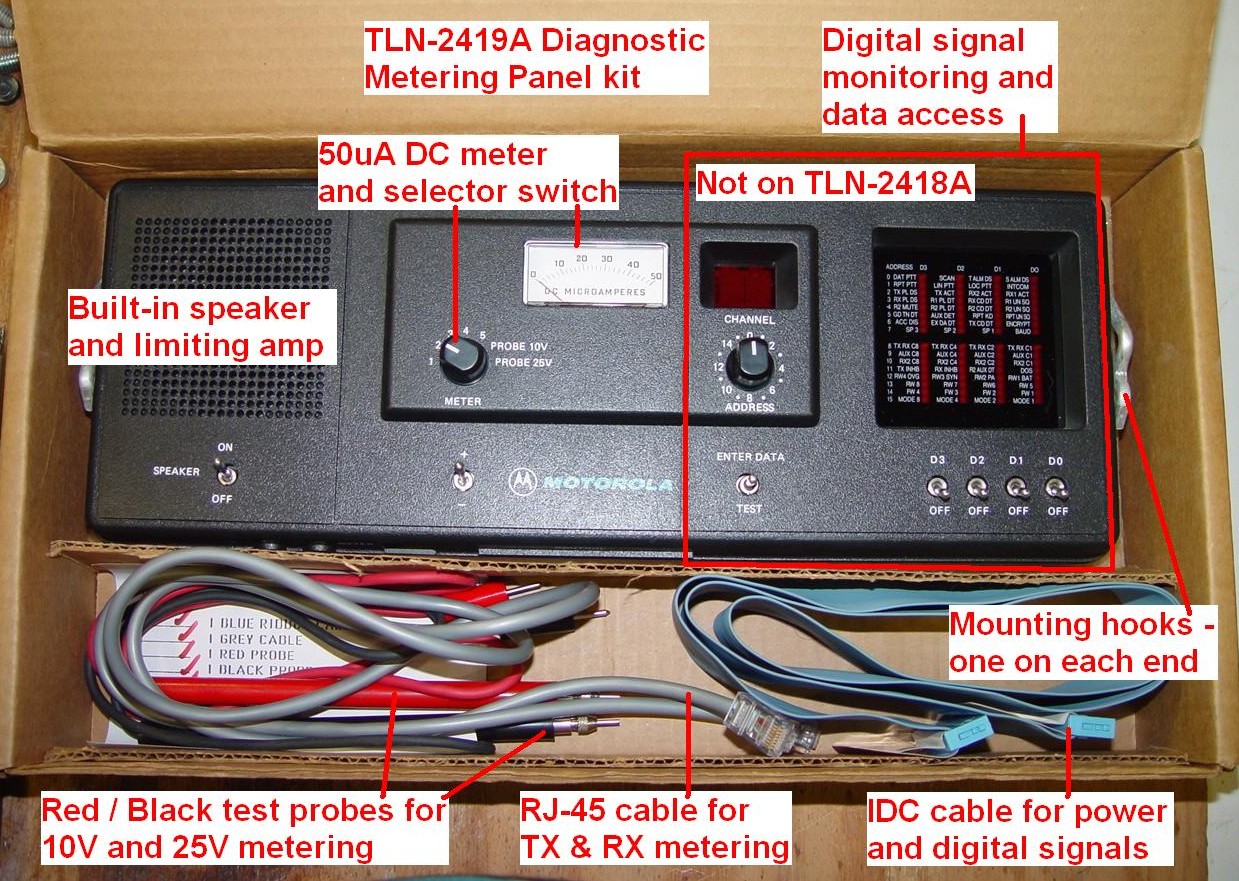
Note that the LEDs and associated switches are not present on the RMP. I have outlined this area that is just a blank plastic area.
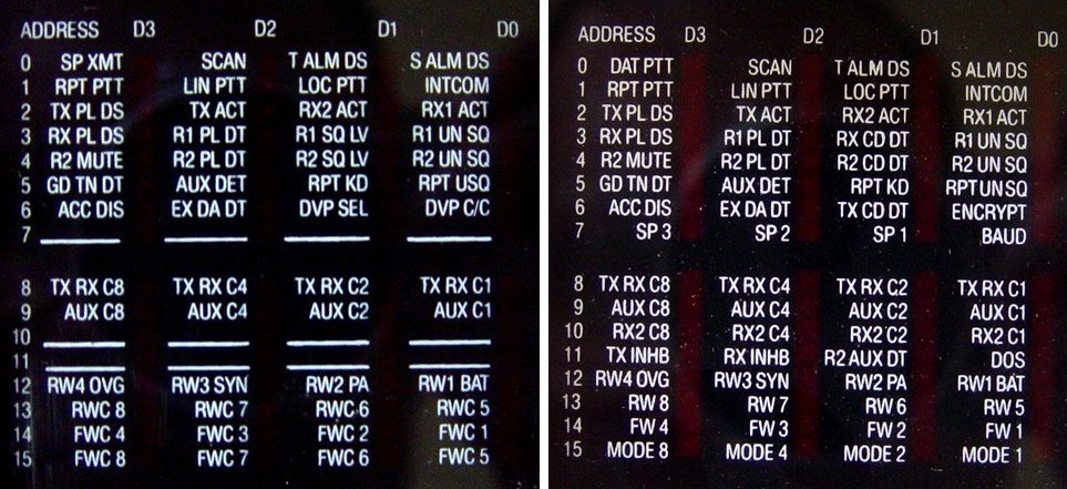
I have seen two versions of the digital display. The screen on the left might just be an earlier revision, or perhaps it was designed before the digital stations came out. Several signal names are missing or are slightly different. Electrically, the two DMPs are the same.
The switches have rather long handles and can easily be broken off if the metering panel is dropped (been there, done that). Of course, such parts are No Longer Available from Motorola and they aren't commonly available through the major parts houses.
When the mounting rods are extended from the meter housing, their hooked ends can fit into any of the holes in the frame rails. One convenient spot is right above the power amplifier, but on shorter cabinets, you may have to put it under the power amp or let it rest on top of the cabinet. There are rubber feet on the back of the meter for this purpose. The 40-pin flat cable plugs into the expansion jack on top of the control tray. The RJ-45 plug goes into either the Receive or Transmit metering jacks on the front of the RF tray, or the metering jack inside (or on some models, on the front of) the power amplifier. Here's a photo of the entire setup:

The MSF5000 manual mentions a Digital Tuning Tool kit, TRN7794A. This is a plastic pouch with several alignment tools and a tuning cable. The most used tool is the 5mm Allen hex wrench, which fits the cores on the receiver front end, the two VCOs, and the internal filter/duplexer. The other useful component is the tuning cable. One end has a BNC male for connection to a meter or signal generator. The other end fits into the tuning holes adjacent to the tuning cores on the receiver front end and the internal filter/duplexer. About 5/8 of an inch of exposed (insulated) center conductor goes into the hole while the metal spring clip keeps it in place. This lets a small amount of signal leak in to, or out of, the particular stage being tuned. This cable has about 30dB of attenuation when compared to a direct connection to the front end. A few other tools could be useful for adjusting the reference oscillator and several potentiometers on the Uniboard in the RF tray. Here are the components of one such tool kit:

All the hardware on the MSF5000 is Metric thread with Torx head. I found the Eklind Ergo-Fold key set, green (Torx), p/n 25581, for about $10. It has T8, T10, T15, T20, T25, T27, T30, and T40 sizes. These will fit a lot of other Motorola radios such as MaxTrac, Spectra, and Nucleus. While not really used for "tuning", this tool was all I needed to take things apart for this photo tour. I highly recommend it for anyone working on Motorola equipment with Torx hardware.
The analog stations need a means of setting the tuning channel for alignment purposes if there is no DC Remote Control board present. Motorola provided a "tuning plug", part number 0180765D49, that plugs into the remote control socket on the SCB to tell the controller that a DC Remote Control board is present (by grounding pin 11) and channel zero is selected (all other pins floating). This plug is a keyed 26-pin connector with one jumper wire going from pin 11 (DC/TRC select) to pin 26 (Logic Ground). Here's a photo of one:

While you can kludge something up with a 50uA DC meter and an old network cable, a real metering panel is the way to go. Plus, it lets you hear the received signal. The digital model is preferred, because of the things you can see and do with it. And, it's the only unit that will let you know if the receiver and repeater squelches are open. The RSS has the ability to monitor and set the 64 digital signals just like the meter does, but dragging a laptop with you is harder than a DMP.
To align the front end and internal filter/duplexer, a good RF signal generator is required. The VCO and mixer coils are aligned using just the receive and transmit metering.
To align the internal filter/duplexer, an RF milli-voltmeter is recommended, although you could use a spectrum analyzer. The meter is more sensitive and easier to operate, plus it's probably high impedance. It would be connected to the tuning cable, which is inserted into the tuning holes on the filter/duplexer. The signal level coming out of the cable is about 30dB less than the signal you feed into the filter/duplexer during alignment.
An AC voltmeter and audio oscillator would be used to adjust the various two- and four-wire line levels and set deviation.
A good wattmeter with the appropriate elements or ranges, and a good dummy load, will be needed to set the transmitter's output power level.
A means of measuring deviation would be necessary to thoroughly align the station's audio levels. This can be a spectrum analyzer, a station monitor, or a deviation meter.
A local microphone, with a 6-conductor RJ11-style connector, is useful for occasional tests, but it's not really necessary. A handset can also be used; there is a small audio amplifier on the SSCB that has just about enough power to drive an earphone.
These are all for the digital-capable station unless marked. Some of them are still available new.
The "MSF5000 Introduction" manual is a 14-page Technical Executive Summary type of write-up and is part number 6881063E47. ANALOG.
The Installation manual, 6881092E05, provides alignment, operation, limited circuit theory, installation, error codes, specifications, etc., for all models.
The UHF Service manual, 6881092E80 covers alignment, operation, and minimal troubleshooting, and has schematics, parts lists, and board layouts for the Uniboard, front end, and control tray ONLY. It has nothing on the power amplifiers, power supply, intermediate power amplifier, or VCOs. There are similar manuals for the other bands.
An older, obsolete manual is 6881062E75, the "MSF-5000 Base Station and Repeater 403-470MHz Continuous Duty". ANALOG.
The Options manual, 6881080E30, is an expensive list of some of the available options. It is not at all complete and not terribly helpful once you own the system.
There is a huge UHF Instruction manual, 6881082E10, which is obsolete and has likely been replaced by the band-specific service manual. It contains schematics and parts lists for EVERY unit (PA, PS, RF tray, Control tray) and has detailed theory of operation.
Part of the above big book is a User manual, 6881082E05, which is obsolete and has likely been replaced by the installation manual. ANALOG.
The digital-capable stations (CXB, RLB, GFB) are programmed using Radio Service Software (RSS) and all the paraphernalia that goes along with it (cables, RIB, DOS computer). The last product number was RVN-4077G and it had revision R05.21.00. The manual that came with it, 6881125E68 (MSF5000 Digital Field Programming User's Guide), is almost an inch thick and has a glued binding. I bought my copy of the package for $75US in 2002 - definitely worth it. One program handles the entire MSF5000 product line. Of course, the software is No Longer Available.
This package runs on MS-DOS platforms (no Windows or DOS-box) and works fine on an 850 MHz Pentium-2 laptop. Unlike some other products, this one does not seem to care about the speed of the computer. It communicates with the station at 1200 baud. The station and RSS can be configured to operate through a pair of modems if remote access is desired.
When the station is sending code plug data back and forth via RSS, the display may show "Prg" if the firmware is new enough. Otherwise nothing special will be shown.
The stations can have up to 8 characters for a CW ID. Hang-time, ID delay, tone frequency, and CW speed are fully adjustable. Time-out timers can also be enabled.
The analog stations (CLB) use 2732 family EPROMs to hold the code plugs. The Station Control Module has one, the Tone Remote Control board has one, and a community tone deck has one. The DC Remote Control board and the Trunking Remote Control board do not. The EPROMs are programmed using the Motorola R1801 Suitcase Programmer with the appropriate firmware and socket adapter. These units are expensive and you either need a supply of erased EPROMs or an ultraviolet eraser. There are dozens of parameters in the MSF5000, and the programmer runs you through most of them. I've never seen one up close, nor have I ever played with an analog station, but after working with digital-capable ones, I'll stick with RSS. It's much better for experimenting and fooling around with.
The analog stations can send the CW ID every 15 minutes with the speed and tone
controlled by bytes in the code plug, but the values in those bytes are not changeable
by the R1801 Suitcase Programmer. This makes the CLB stations undesirable for amateur
use without an external repeater controller. The other parameters are changeable.
Update: There is now a ham-written program that allows modification of the EPROM image
file including the IDer spacing and tone frequelcy.
More detailed articles on programming both the analog and digital-capable stations can be found in the MSF section of the Repeater-Builder web site.
The following were taken with the DMP using the configuration seen earlier.
Typical meter readings with no signal, dummy load attached (C74CXB-7106BT), at the RF Tray Receive Metering Jack:
| Pos | Signal Name | uA |
|---|---|---|
| 1 | Quadrature Detector | 22 |
| 2 | I.F. Signal Amplitude [1] | 10 |
| 3 | Mixer Local Oscillator | 26 |
| 4 | Reference Oscillator | 16 |
| 5 | RX VCO Steering Line [2] | 38 |
Notes:
[1]: This is the "S-Meter" equivalent, and typically ranges from 10 to 40. 20dB quieting is
typically achieved between 12 and 14uA.
[2]: VHF station VCOs are not adjustable. The M5 value should be between 10 and 45.
Typical UHF receive signal strength meter position 2:
| uA | dBm | uV |
|---|---|---|
| 10.0 | -131.0 | 0.063 |
| 10.5 | -127.0 | 0.100 |
| 11.0 | -121.0 | 0.200 |
| 12.0 | -117.0 | 0.317 |
| 14.0 | -111.5 | 0.600 |
| 16.0 | -108.0 | 0.891 |
| 18.0 | -105.0 | 1.260 |
| 20.0 | -101.5 | 1.890 |
| 22.0 | -97.5 | 3.000 |
| 24.0 | -89.5 | 7.500 |
| 26.0 | -85.0 | 12.600 |
| 28.0 | -82.5 | 16.850 |
| 30.0 | -80.5 | 21.200 |
| 32.0 | -79.0 | 25.200 |
| 34.0 | -77.5 | 29.800 |
| 36.0 | -76.0 | 35.500 |
| 38.0 | -74.0 | 44.700 |
| 39.0 | -72.5 | 53.200 |
| 40.0 | -70.0 | 70.900 |
Transmit meter readings were taken first in receive, then the transmitter was keyed and they were taken again. This is the 110-watt station, producing about 100 watts out of the PA, which leaves 60 watts out of the internal filter/duplexer feeding a dummy load. These are the readings at the RF Tray Receive and Transmit Metering Jack:
| Pos | Signal Name | uA (RX) | uA (TX) |
|---|---|---|---|
| 1 | Final Forward | 0 | 24 |
| 2 | Final Reflected [1] | 0 | 26 |
| 3 | Power Control | 22 | 16 |
| 4 | Driver Forward [1] | 0 | 0 |
| 5 | TX VCO Steering Line [2] | 38 | 38 |
Notes:
[1]: These may only be meaningful on 250 watt or trunking stations.
[2]: VHF station VCOs are not adjustable. The M5 value should be between 10 and 45.
I measured the M1 (final forward) signal on my 80w repeater while measuring the raw PA output power into a dummy load. The results are tabulated here. This value depends on the power capability of the PA; a reading of 24-28 would be the normal range.
| uA | Watts |
|---|---|
| 12 | 20 |
| 15 | 30 |
| 18 | 40 |
| 21 | 50 |
| 24 | 60 |
| 26 | 70 |
| 28 | 80 |
| 30 | 90 |
| 32 | 100 |
Unless otherwise noted, all photographs were taken by the author and are copyright by him.
Several people proofread this article and gave me valuable information.
Thanks go to Bernie KH6IAH for providing a clear photo of another secure board. He also provided some fine points about the operation of analog stations.
Ed WØSD did the research and testing of the Anderson Powerpole connectors on his stations. Eric WB6FLY mentioned the AMP connectors in an article about the MTR2000 elsewhere on this website.
Steve KC6TLO provided the inside photo of the 75-watt power amplifier.
Roger W5RD supplied photos of his 896 MHz trunking repeater, soon to become a 900 MHz amateur repeater. He also took the detailed photos of the high-stability oscillator at the bottom of his station.
Gary AGØN supplied the photo of the bad C706 on the analog station control board.
Don W9SL supplied the photos of the green and yellow band TEE cables.
Tim W5FN supplied the photo of the blown-up C461 on the VHF IPA board.
Mark W1ACP supplied the photos of the VHF front panel, receiver front end, and VCO.
Bob VE3DJ supplied photos of the VHF receiver pre-selector.
Sam WM4T supplied the photo of the VHF power amplifier connector area.
Mike KØHYT supplied the photo of the junction box on the UHF internal filter/duplexer TEE cable.
Glen K6KJQ supplied the photo of the VHF battery-reverting power supply.
MSF5000, MaxTrac, Spectra, MICOR, Nucleus, DPL, PL, and a whole lot of other terms, are trademarks of Motorola, Inc.
The TEE cable diagram and chart came from official Motorola service manuals and hence are copyrighted by Motorola. Additional information came from some MSF5000 training videos and various manuals.
Power Lock Series II connectors are trademark of AMP Corporation.
Singlepole, Powerpole, and PP75 connector names are trademarks of Anderson Power Products.
Molex is a trademark of Molex, Inc.
The author can be contacted at: his-callsign [ at ] comcast [ dot ] net.
Back to the top of the page
Up one level (MSF index)
Up two levels (Moto index)
Back to Home
This article was created in March 2006.
It was re-converted from the source to HTML by the author 20-Dec-13.
Article text, hand-coded HTML, and most of the photos © Copyright 2006 and 2013 by Robert W. Meister WA1MIK.
This web page, this web site, the information presented in and on its pages and in these modifications and conversions is © Copyrighted 1995 and (date of last update) by Kevin Custer W3KKC and multiple originating authors. All Rights Reserved, including that of paper and web publication elsewhere.