Up two levels (Main Moto Index)
Back to Home
Modular Connectors
By Robert W. Meister WA1MIK

|
Up one level (MTR2000 Index) Up two levels (Main Moto Index) Back to Home |
MTR2000 Front Panel Modular Connectors By Robert W. Meister WA1MIK |
|
Looking down into the connectors on the front edge of the Station Control Module, from above the station, pin 1 is to the left, towards the BNC jack. A red mark has been placed over pin 1 in each of the jacks in the photo below.
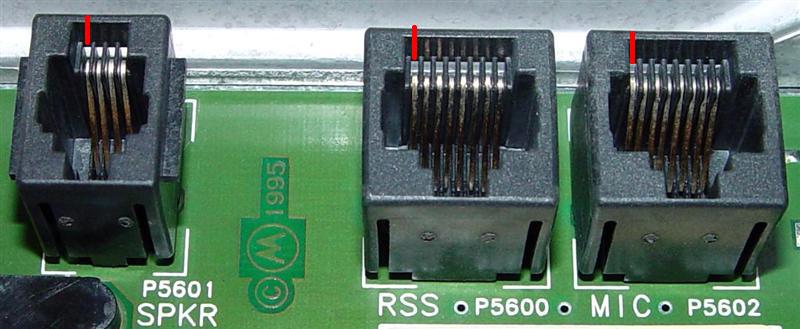
SPKR (P5601):
The speaker jack is a 4-position, 4-conductor modular jack that is meant for an amplified speaker, an HSN1000 or HSN1006, through an adapter cable, part # 0185180U01. Note that this is the same size modular connector used for wired telephone handsets. It is NOT the same one you commonly find on cables that plug in to the modular jacks on modems; those are 6-position, 4-conductor connectors and they will not fit the MTR2000 (I found out after I had cut a cable in half). The Line Audio Out is capable of driving a load impedance of 2400 ohms (or greater) to a level of 500mVAC at 60% system deviation, according to the manual. This is not meant to drive a loudspeaker directly, although it will do so, at very reduced volume (in a pinch it's better than nothing at all). The higher the impedance of the speaker, the louder it will sound. At maximum volume with no speaker attached, I measured about 1200mVAC on a 400 Hz tone with 3 kHz of deviation (but it would not go any higher; something internal to the station limits at around 3 kHz). The signals available are described in the table below.
| Pin# | Signal Name |
|---|---|
| 1 | See note below |
| 2 | +14.2VDC at 1A |
| 3 | Ground |
| 4 | Line Audio Out |
NOTE: Pin 1 is shown as Not Connected in the MTR2000, but it goes to ground in the MTR3000. The speaker adapter cable uses all four pins and connects pin 1 to a power ground signal.
You could connect the Line Audio Out to an amplified computer speaker if you make an appropriate adapter cable.
RSS (P5600):
The RSS connector is an 8-position, 8-conductor modular (RJ45) jack that provides EIA/RS-232 communication level signals to a programming computer. Only pins 5, 6, and 7 are necessary for communications as RSS supposedly operates at 9600 baud, 8 data bits, no parity, and uses Xon/Xoff for throughput control. The signals available are described in the table below. I don't know if the other pins would be properly supported by RSS if wired to a computer's serial port.
| Pin# | Signal Name |
|---|---|
| 1 | CTS (Clear To Send) |
| 2 | RTS (Request To Send) |
| 3 | Not Used |
| 4 | DTR (Data Terminal Ready) |
| 5 | Ground |
| 6 | TXD (Transmit Data Out) |
| 7 | RXD (Receive Data In) |
| 8 | DCD (Data Carrier Detect) |
MIC (P5602):
The service mike connector is an 8-position, 8-conductor modular (RJ45) jack meant for a GMN6147B or equivalent microphone. This microphone has three unlabeled momentary pushbuttons on the right side for speaker volume adjust/step, monitor, and intercom on/off. Naturally there's a PTT button as well. Here's a photo showing the front and side views.
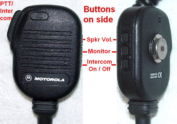
Even if there was a speaker built into this mike, the MTR2000 doesn't use it. (The grille is totally solid but it looks like they might have used the same mold for a speaker/mike at one time.) The signals used by the station are described in the table below.
| Pin# | Signal Name |
|---|---|
| 1 | Not Used |
| 2 | Control |
| 3 | PTT |
| 4 | Mike Audio |
| 5 | Ground |
| 6 | Not Used |
| 7 | Not Used |
| 8 | Not Used |
These signals and pin numbers look familiar. A MaxTrac mobile radio microphone (HMN1056A, for example) has the following connections.
| Pin# | Signal Name |
|---|---|
| 1 | Not Used |
| 2 | Not Used |
| 3 | Hang-Up |
| 4 | Ground |
| 5 | Mike Audio |
| 6 | PTT |
| 7 | Not Used |
| 8 | Not Used |
The pins on the MaxTrac mike and jack are numbered opposite from the MTR2000, so if you reverse the order, you'll see that MaxTrac pins 6, 5, and 4, are equivalent to MTR2000 pins 3, 4, and 5, which have the same PTT, Mike Audio, and Ground signals on them. This means you can plug a MaxTrac microphone into the MTR2000 and at least get PTT and local mike audio out of it (it works great; I tried it). You won't have the other functions available on the GMN6147B mike though.
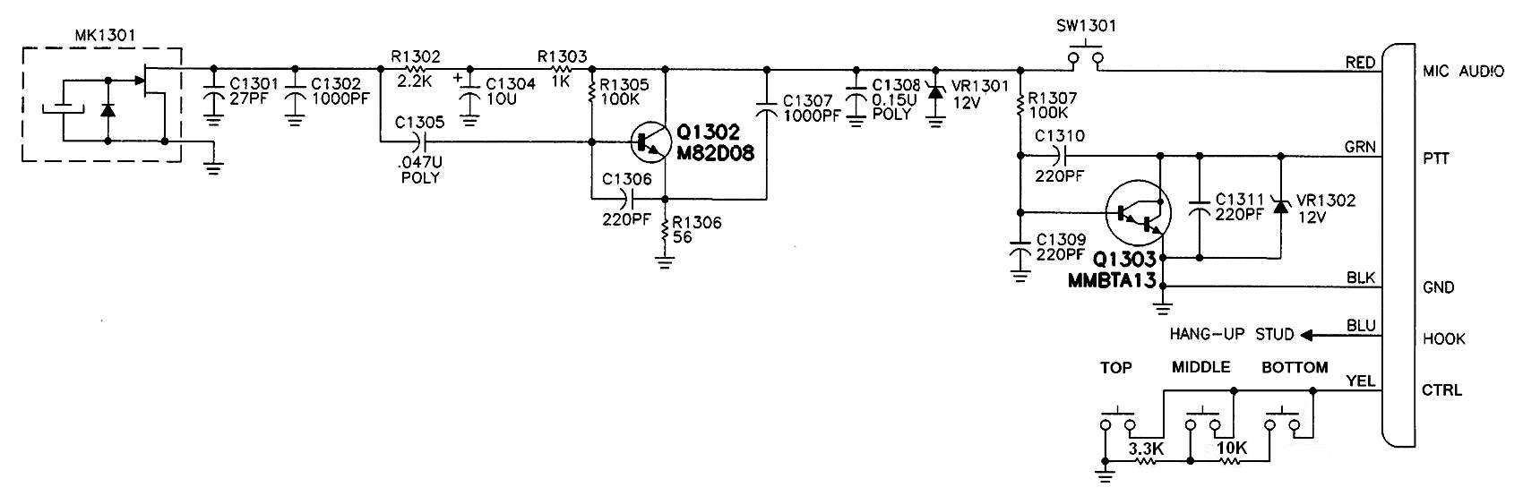
Speaking of the service microphone, I purchased a used one and measured the Control line to ground. Activation of any single pushbutton pulls this line to ground with some amount of resistance, as listed in the table below. I also inserted a breakout box and measured the voltage on the Control line. The station determines which function to perform based on the analog voltage on this input.
| Button | Function | Resistance | Voltage |
|---|---|---|---|
| Top | Speaker Volume | 1.5 ohms | 0.00V |
| Middle | Monitor On/Off | 3.3k ohms | 1.95V |
| Bottom | Intercom On/Off | 13.4k ohms | 3.60V |
| None | Nothing | Infinite | 4.99V |
Here's an equivalent schematic (based on an HMN3596A) showing the switches and resistors. The actual pin numbers can be determined from the information shown in previous tables. Click on the photo for a larger view.
For what it's worth, the microphone is hermetically sealed and does not come apart. The cable is detachable and has another 8P8C modular plug at the microphone end. It is part number 3005648V15 and lists for about $22US. The PTT signal is electronic; the PTT switch does not ground this line unless the mike is plugged into a working station. Although not used by the MTR2000, the mike has a hang-up clip on the back and it does activate the hang-up line when grounded. For completeness, the wire colors (in case you need to replace the modular plug; the tab was broken on mine) are in the following order. With the contacts facing up, the cable coming out the bottom, the locking tab on the back, from left to right, they are: Yellow, Green, Orange, Blue, Red, Violet, Brown, and Black.
Credits, Acknowledgements, and Contact Information:
The pin number information came from the MTR2000 Detailed Service Manual and MTR2000 Installation and Operation Manual. Additional information came from actual tests with a 100w UHF station.
The author can be contacted at: his-callsign [ at ] comcast [ dot ] net.
Back to the top of the page
Up one level (MTR2000 Index)
Up two levels (Main Moto Index)
Back to Home
This page originally posted on 05-Jun-2011
Article text, photos, and hand-coded HTML © Copyright 2011 by Robert W. Meister WA1MIK.
This web page, this web site, the information presented in and on its pages and in these modifications and conversions is © Copyrighted 1995 and (date of last update) by Kevin Custer W3KKC and multiple originating authors. All Rights Reserved, including that of paper and web publication elsewhere.