Up two levels (Main Moto Index)
Back to Home
By the Reno Ham Radio Club W7RHC
HTML'ed and Edited for this web site by Mike Morris WA6ILQ

|
Up one level (MTR2000 Index) Up two levels (Main Moto Index) Back to Home |
Interfacing the Motorola MTR2000 to an External Controller By the Reno Ham Radio Club W7RHC HTML'ed and Edited for this web site by Mike Morris WA6ILQ |
|
Editors note: The author selectrd an RC-210 controller but the information below is applicable to any controller that has separate inputs for COR and tone decode, and a PTT output. This includes Scom, Arcom, RLC, and several others.
Our club was given a 100 watt UHF MTR2000 repeater and it is the version that has an external receiver pre-selector. While the MTR has a very capable internal controller we wanted to use an external controller that would support link radios for better geographical area coverage and flexibility. We chose the Arcom RC210, but the information below is applicable to any controller that has separate inputs for COR and tone decode, and a PTT output.
We had available the MTR RSS program, the programming cable, and a club member that is familiar with MTR2000 repeaters.
Editors note: The RSS program runs on a 32-bit Windows system (XP, Win-7-32, Win-8-32 or Win-10-32) and will NOT run on any 64-bit Windows.
Before beginning modifications to any station, it is highly recommended that you first test the station operation "as is". Do not assume the station, its features or options to be working properly simply because they are physically present. Unless you are very, very lucky, you can be assured some audio level adjustments and programming tweaks are going to be required before the station is put into service. The MTR is a "no screwdriver" device and all adjustments are made with the RSS
The system connector on the rear of the station is a 96-pin (3 rows of 32 pins) female "Euro" Connector. Motorola prefers that you order their kit number 3083908X02, "System Connector Cable Kit" which contains a housing shell for the 96 pin system interface connector, the male conenctor itself, 30 loose pins, and 30 more pins preterminated with 24 gauge, 2 meter long wires (the MTR2000 is made in Israel, and everything about it is metric). This connector kit is priced at about $48 (early 2008 price). You can also get the same connector from Digi-Key in a couple of different varieties for a lot less money (about $5). I used their part number A1265-ND, which had nice long 0.5 inch pins sticking out the backside.
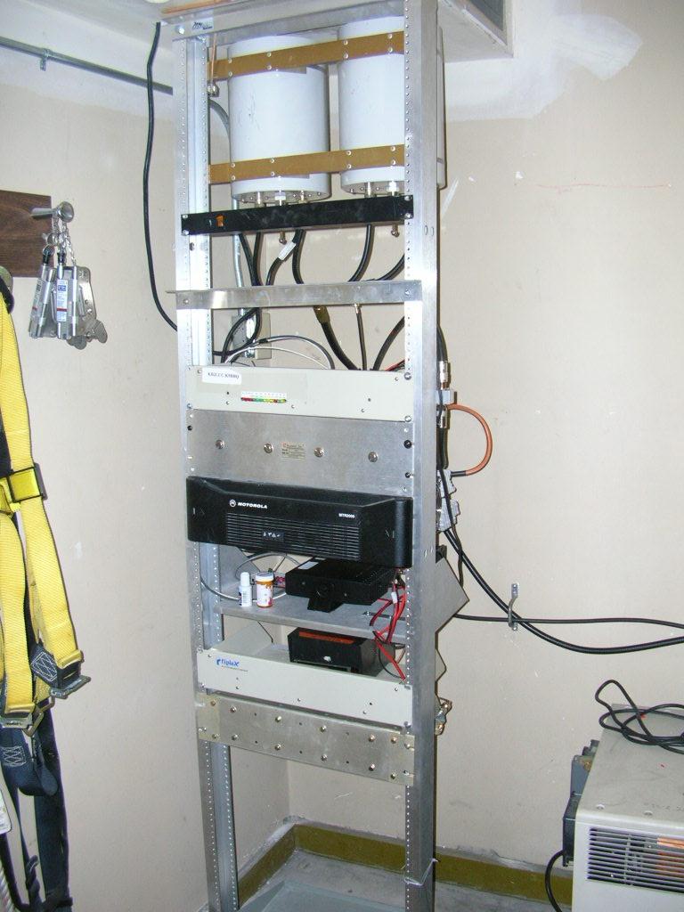
The rear of the station with the covers removed. More information
on the MTR is in other articles at this web site.
The Station Interface:
The physical connections to the station are straightforward: AC Power (a common computer IEC connector), receive antenna, transmit antenna, DC Battery backup connector (regular Anderson Powerpoles), an unused trunking controller / MRTI connector, and the 96-pin system connector. The trunking / MRTI connector was originally designed as the "Mobile Radio Telephone Interface" for the MSF5000 and connected to a Motorola specific autopatch box. When trunking systems became common the MRTI interface was enhanced to support that. Since 99% of our users have cellphones plus the Arcom has an autopatch option we ignored the MRTI connector.
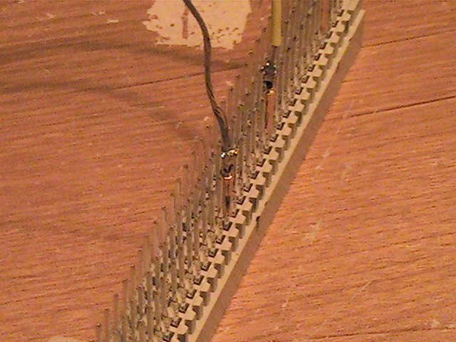
The connector has 3 rows, labeled A, B, and C, each with 32 pins, with row C at the top, and A at the bottom. I used insert pins intended for a DB25 female connector - I soldered the wires onto them, then slipped them over the connector pins, and then put sheat-shrink over that.
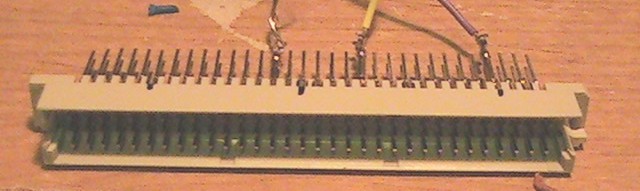
Here's another view of the plug:
IMPORTANT
The back of the station female connector is clearly labeled, but the
pin numbers in the Digikey connector body (i.e. the pin numbers molded
into the male connector body) are different.
The numbering of the connector on the rear of the radio is simple:
C 01 02 03 04 05 06 07 08 09 10 11 12 13 14 15 16 17 18 19 20 21 22 23 24 25 26 27 28 29 30 31 32 C
B 01 02 03 04 05 06 07 08 09 10 11 12 13 14 15 16 17 18 19 20 21 22 23 24 25 26 27 28 29 30 31 32 B
A 01 02 03 04 05 06 07 08 09 10 11 12 13 14 15 16 17 18 19 20 21 22 23 24 25 26 27 28 29 30 31 32 A
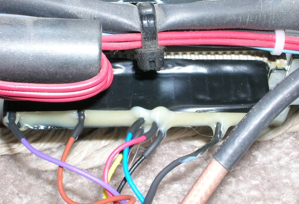
Once the connections were all checked, verified and working well we insulated all the pins (even the unused ones) with heat shrink tubing. Yes, 96 pieces of heat shrink. And when all that was done the whole connector was "potted" with hot-melt glue. This keeps pins from getting bent and shorting out. A layer of black tape over that provides the final "wrap".
Here's a photo of the finished connector plugged into the back of the MTR:
The following describes the connections to the J5 System Connector that we used and their functions:
| Row | Pin | Voltage and Polarity | Name | Description |
|---|---|---|---|---|
| A | 04 | TTL output active low | AC Power Fail indicator | This pin is pulled up when idle by a 10K resistor to +5vDC. When active
it is pulled to ground. This is a logic output, not a relay driver. If you implement battery backup as per Eric Lemmon's article at this web site your radio will ride through any power outages that do not exhaust the repeater battery. When AC power to the MTR fails this pin goes to ground and stays there for the duration of the AC power outage. You could connect this pin to an unused logic input on your repeater controller and (depending on the programming) you can have the controller announce "A C power failure at (time)" and the courtesy beep can change, for example from a simple single beep to the Morse "B" (indicating operation from battery). Even the users that can't read Morse can catch that big a difference. When the power comes back you can have the controller announce "A C power restored at (time)" and restore the normal courtesy beep. |
| A | 10 | TTL output active low | VSWR Fail indicator | This pin is pulled up when idle by a 10K resistor to +5v DC. When
active it is pulled to ground. This is a logic output, not a relay driver. Do a similar connection from this pin to another logic input on your controller and it can announce an antenna system problem. Maybe change the courtesy beep to the Morse "A". |
| A | 17 | Auxiliary Transmit Audio Input (AuxTxA) |
The audio level sensitivity of this input must be set in the RSS. By default, the value is zero (off), and no transmit audio applied to this pin will be heard until this is corrected. This level may or may not be set to a non-zero value on your new-to-you MTR, depending on its previous programming. Connect this pin to the transmit audio out on the controller. This input was originally intended for a paging encoder. The manual recommends that you use a 100 µF electrolytic to AC couple to this input (+ side towards MTR), but the Zetron-made Motorola paging interface (CDN6351A) uses a 10 µF capacitor but you may not need it as many brands of external controllers have some sort of DC blocking capacitor already inside, so the check your controller schematic. | |
| B | 4 | TTL output active high | Carrier Detect | This pin is active when a carrier is present, regardless of the state of the reciever PL / DPL decoder squelch setting, hence it detects all carriers on the receiver frequency. Other common names for this pin are COR and COS. |
| C | 2 | TTL output active high | Receiver Un-Squelched (RUS) | This pin is active when the receiver audio is active (i.e. the receiver is un-squelched). If the station is programmed for CTCSS or DCS (a.k.a. DPL), this line only activates on the proper tone or code. If programmed for carrier squelch, this can be COS / COR. Normally for your external controller you would use pin B4 as COS and pin C2 as the PL Valid, or PL Indicate signal. |
| C | 10 | TTL input active low | External PTT (EPTT) |
This signal must be mapped in RSS to "Wire Line and Auxiliary
Audio" for external controllers. Otherwise the audio path from the auxiliary
transmit audio input will not be enabled and no transmit audio will be heard.
Applying a ground to this pin will activate the stations transmitter. The
MTR programming includes a timeout timer. If you trust your external controller you can disable that. Note: When this pin is grounded the internal PL Encode is shut off. The Zetron-made Motorola paging interface (CDN6351A) has two inputs, one for an external tone encoder and a second for repeat audio. This could also be accomplished with a simple resistive mixer. |
| C | 17 | Discriminator Audio Output | This pin is the audio from the MTR receiver to your controller. Note that this pin can deliver non-de-emphasized (flat) or de-emphasized audio, and which one is determined in the programming (see the notes at the end of this table). | |
| A B C | 20 | +5vDC | Logic DC Power |
Column 20 on the connector is +5 Volts DC. Total current through all three pins in parallel (summed) must not exceed 500 mA. |
| A B C | 32 | +14.2vDC | Main DC Power |
Column 32 on the connector is +14.2 Volts. Total current through all three pins in parallel (summed) not to exceed 1.0 Amp. One amp of DC power is plenty to power an external controller but we did not attempt that. The price of an MTR2000 is MUCH more than an external power supply. We didn't want to fry anything. On top of that, we had a Maxtrac link radio that needed several amps of power so we had to provide an external supply regardless. |
| A B C | 19, 27 and 31 | Ground | DC Ground and Audio Ground | There are no seperate analog / digital / frame grounds. Total ground current through all 9 pins (summed) not to exceed 1.5A |
Additional comments on the Discriminator Audio Output pin and Pre / De-emphasis:
The RSS allows you to set this pin for flat audio and Same as wire line. The flat audio option disables the de-emphasis, the other enables it. Make sure that you choose the correct audio (flat versus pre-emphasized) for your application.
Since we are using de-emphasized audio on our link radio, when we used pre-emphasized audio (unprocessed discriminator) from the MTR receiver, we wound up with a "mismatch" between the two radio ports on the controller when they were transmitted.
We were tired and completely missed it.
It sounded great when the MTR receiver (flat unprocessed discriminator audio) was fed thru the RC-210 (it's jumper was set for flat) then out the MTR transmitter (also set for flat).
But the link port radio of the RC-210 was using de-emphasized audio. So the choice on the RC-210 was flat or de-emphasized (again). When link audio was transmitted thru the MTR it sounded muffled on "flat", and VERY muffled with the de-emphasize jumper set. But the local MTR receiver sounded great.
The fix was in the RC210: The port that was connected to the MTR needed the de-emphasis jumper set for de-emphasis, the link radio port needed the de-emphasis jumper set for de-emphasis, and the MTR transmitter needed pre-emphasis turned on in the RSS programming. Once that was done everything sounded fine.
General interfacing notes:
Before we connected ANYTHING to the rear connector of the MTR2000 we verified that the pins we connected to were the actual signals that we needed. The pin numbers stamped in the connector body were misleading. Once we verified the pin, we also verified that the logic was in the direction we wanted (i.e. active high versus active low).
We used an HP 3551A TIMMS (an audio measuring test set) to verify the receive audio out, and used the generated audio from the TIMMS to verify the transmit audio in.
I am sure you could use any audio source to generate, and an oscilloscope to verify "receive". The Radio Shack mini audio amplifier (model 277-1008, under $20) is a great little workbench tool for this kind of signal tracing.
PL detect and Carrier detect can be verified with a common VOM.
Simply grounding the PTT line checks the transmit PTT signal. Make sure that you have an adequate dummy load (or the antenna system) connected!
The point is to make sure you have the correct signals, and logic levels before connecting to an external controller.
The last part (which took very little time) was to set the DTMF decode level into the RC210 controller, then the repeat audio levels from both the link radio and the local MTR receiver. Since a club member has a Motorola R2600 service monitor, we used the service monitor "duplex" mode. We generated 3 KHz deviation of 1 kHz tone and 600 Hz of PL. Then simply set the repeat audio of the controller to match those values on transmit.
Just for general information the rest of the repeater system consists of:
One operational quirk
Having a talking controller, one usually would like to hear the repeater when it actually is talking. The information we found on interfacing to an MTR2000 was usually oriented towards multi-tone (or multi-DPL, or a combination of both), community repeater type operations. As such, a number of those articles recommended setting the MTR2000 to use carrier squelch for transmit and receive, and use an external multi-tone / multi-code "community repeater" panel.
Like other previous people that have posted on the repeater-builder yahoogroup, we wanted to use some form of CTCSS both on transmit and receive.
As others have stated, the "operational quirk" is that the MTR station will only transmit CTCSS / DCS while it is actively receiving it. This means a user running CTCSS / DCS on their receiver will only hear actual repeated transmissions of other users on the LOCAL MTR receiver. The controller-generated system messages and the CWID will be transmitted, but one can only hear them if listening in carrier squelch. The same situation happens with radio traffic coming into the controller from the link radio.
The only fix for this that we have found so far is to either buy the Zetron (Motorola CDN6351) interface and use an external PL encoder or build a similar "summing amp" to accomplish the same function prior to putting that audio into pin A17 (i.e. programming the MTR to not encode PL, and then replacing it with the tone from an external PL encoder mixed into the Auxiliary Transmit Audio Input pin).
Conclusions:
The MTR2000 is an excellent repeater. The built in circulator and fans are great features. We have set the power out at 90 watts. The internal controller is very capable and would work fine if we were not linking to other repeaters in the area.
The interface connections as described above works for us.
Like most projects, you should have the service manual and the schematic before creating this interface for an external controller.
We are not responsible for any mistakes YOU make with pinouts. Please be aware this is just an article for information purposes. We are not looking over your shoulder and will not be responsible for any smoked radios. Good luck!
Contact the Reno Ham Radio Club (W7RHC) trustee with any questions.
Back to the top of the page
Up one level (MTR2000 Index)
Up two levels (Main Moto Index)
Back to Home
This page originally posted on 23-Oct-2008
Article text © Copyright 2008 by Nicholas Manzo W7NIK.
Artistic layout and hand-coded HTML © Copyright 2006 and date of last update by Mike Morris WA6ILQ.
This web page, this web site, the information presented in and on its pages and in these modifications and conversions is © Copyrighted 1995 and (date of last update) by Kevin Custer W3KKC and multiple originating authors. All Rights Reserved, including that of paper and web publication elsewhere.