Up two levels (Main Moto Index)
Back to Home
Motorola MTR2000 UHF
100-watt Repeater Station
By Robert W. Meister WA1MIK

|
Up one level (MTR2000 Index) Up two levels (Main Moto Index) Back to Home |
A Photo Tour of a Motorola MTR2000 UHF 100-watt Repeater Station By Robert W. Meister WA1MIK |
|
Click on any of the outlined photos for a larger view.
This station, which included a Celwave UHF duplexer, Argus battery charger, and cables, was acquired on its way to a dumpster. It had been condemned and written off. There were mouse nests behind and among both of the fans, inside the card cage, and in any space bigger than 1/2 inch. Mouse urine and feces, fur, feathers, leaves, and twigs were over everything. Before I even touched the station, it got thoroughly hosed off outside in the driveway. I then took it apart and cleaned the major assemblies, then took those apart and rinsed everything else out with hot water. I took photos as I was reassembling the station. This unit was put into service in 1998.
In its present condition, it will power up about every two days. It displays an alarm (red flashing Status LED) and does not transmit. So to quote Doctor McCoy, "It's Dead, Jim."
I later purchased a 28V 18A linear DC power supply and connected the station to that with the stock battery cable. The station powered right up, passed all diagnostic tests, shows no failures at all, and seems to be working fine. The 28V DC from the station's switching power supply apparently was not able to supply the required power, thus causing a bunch of errors. I did attempt to take the supply apart, but the way it's been built requires that things be destroyed in the process of removing the circuit board, so I left it as-is. At this time, that assembly takes in 28V and regulates it down to 14V and 5V for use by the rest of the station. The AC input jack has been taped off so it won't ever be used again.
The Argus battery charger had destroyed itself and was thrown away. The Celwave duplexer tuned up and worked perfectly.
Station External Photos:
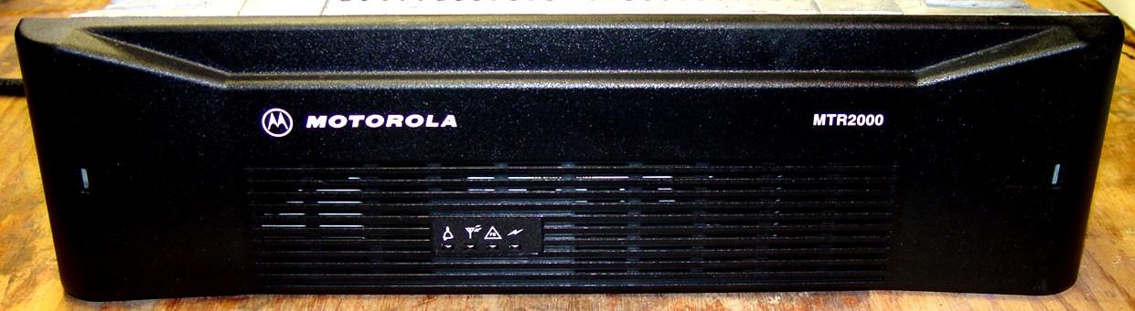
The front cover provides four LED indicators to show the condition of the station. From left to right, they are: Station Status (red/green), RX Active (green), FailSoft (yellow), PA Keyed (green).
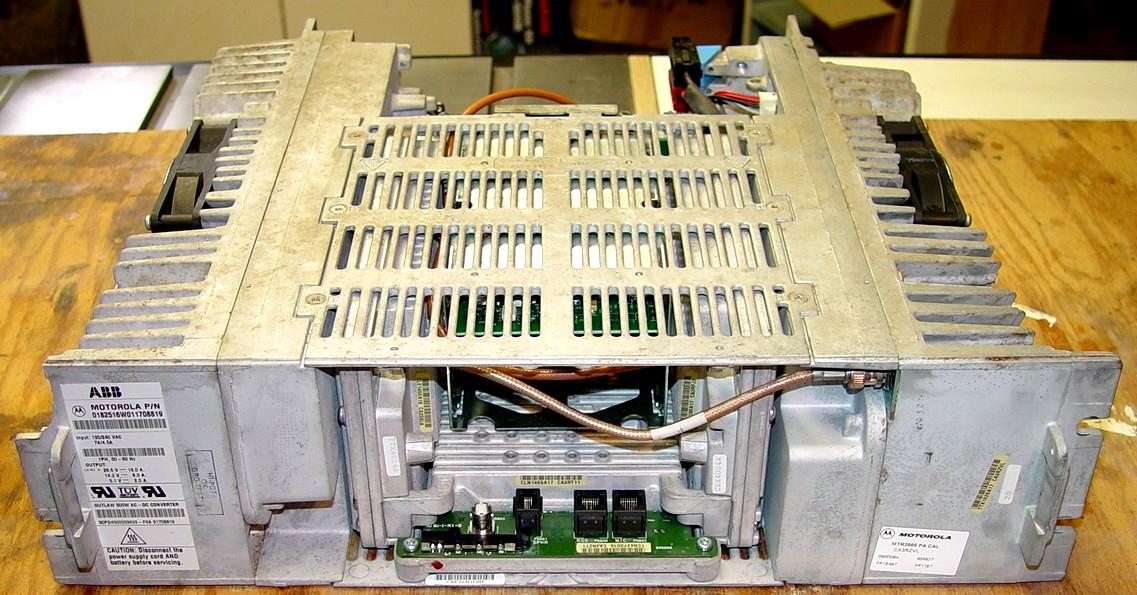
Here's the front of the station after removal of the plastic cover. The power supply (PS) is on the far left, the card cage is top center, the exciter, station control module (SCM), and receiver are the bottom center, and the 100w power amplifier (PA) is on the far right. There's a wire-line card (not visible) plugged into the card cage. There are 12VDC fans mounted on the PS and PA heat sinks. The tan coax jumper cable connects the exciter output to the PA input. Another tan coax cable barely visible above it runs from the back of the station, along the side of the card cage, to the receiver antenna input.
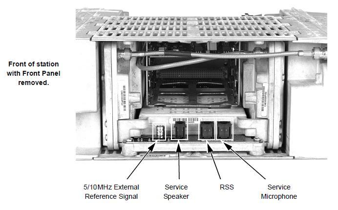
The following diagram of the front of the station was extracted from the Installation and Operation manual.
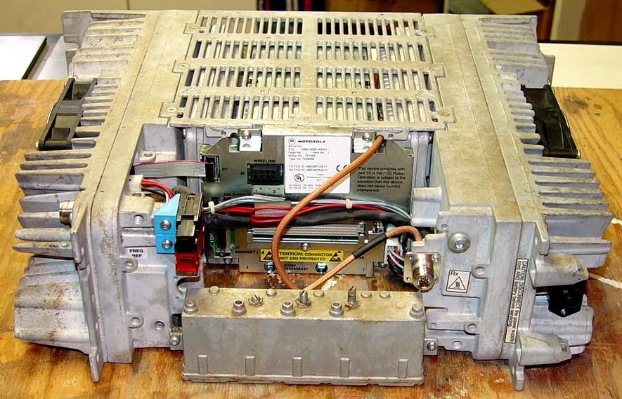
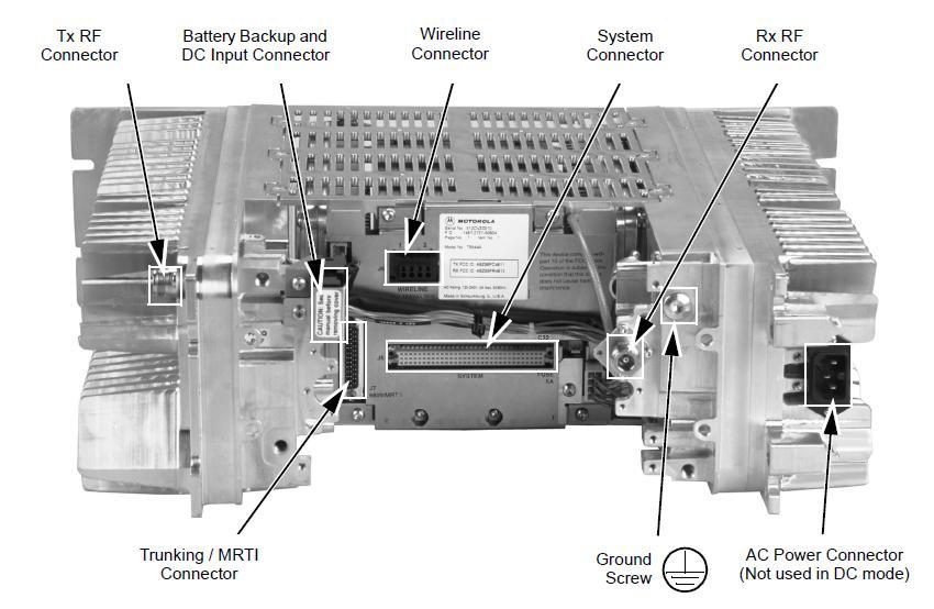
Here's the back of the station. The transmitter output N connector is on the upper left rear outside corner of the PA. The Anderson Power-Pole DC connectors are mounted to the PA. There's an optional receiver pre-selector in the empty space in the middle on the bottom and the tan coax goes through the card cage to the receiver input. On the back of the card cage are the station I/O connectors. The power supply is on the right side. The receiver input N connector is mounted to the PS and another tan coax cable feeds that signal to the pre-selector. If this was a base station, there would be an antenna relay mounted on the back of the station, coax would run from the relay to the receiver, and the receiver's N connector would be the primary station antenna connection. Without the pre-selector, the receiver's N connector goes directly into the receiver's input jack at the front of the station. The coax cables are RG-400 and their lengths are NOT critical.
The following diagram of the rear of the station was extracted from the Installation and Operation manual.
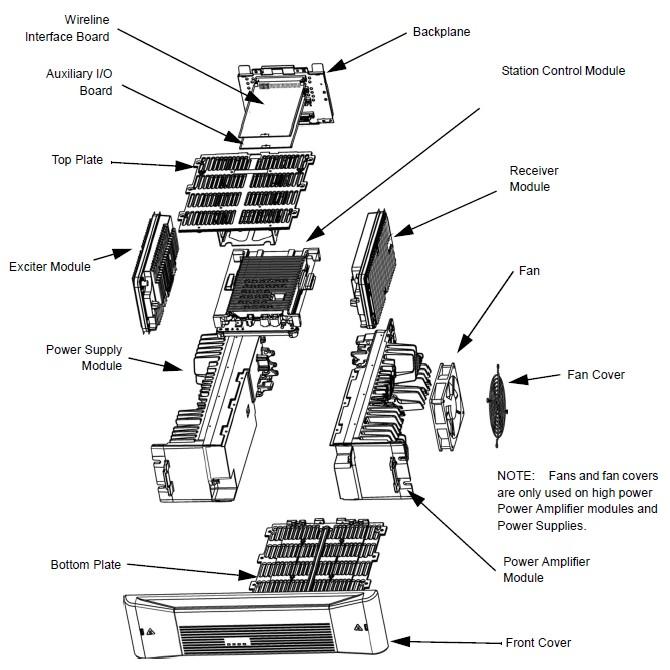
The following exploded diagram of the station was extracted from the Installation and Operation manual.
Module Internal Photos:
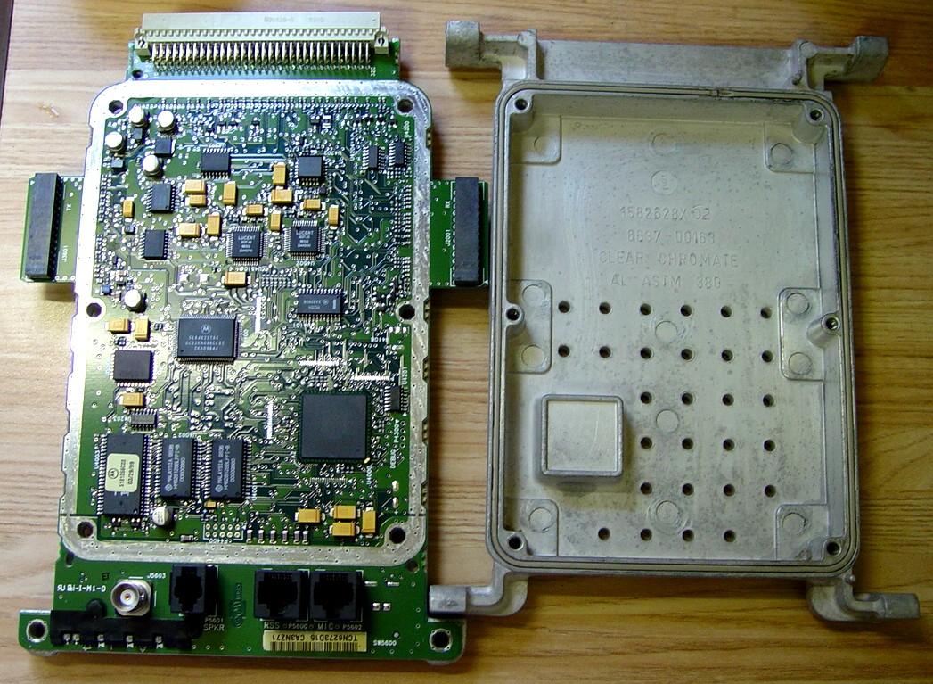
Inside the power supply, photo 1 of 2. This is a sealed module made by ABB and it is basically unrepairable. In fact, everything in the MTR2000 product line is made of Field Replaceable Units (FRUs). Nothing is repairable; the technician just replaces the largest assembly possible. This is a universal switching power supply that accepts 28VDC or 90-260VAC for input and turns that into 28VDC, which it regulates down to 14VDC and 5VDC output. Only the 100w PA needs 28V; lower wattage stations don't need that.
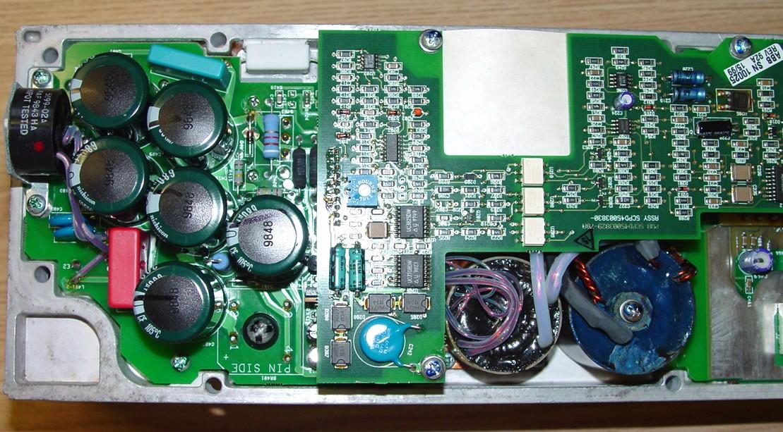
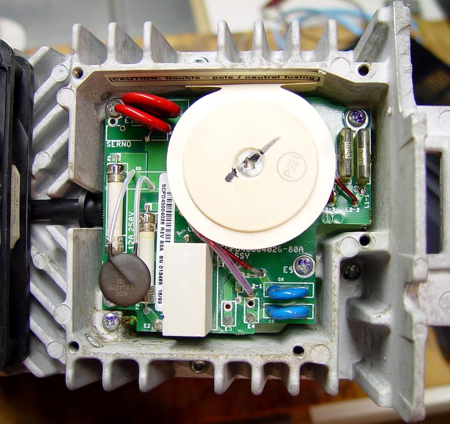
Here's the rest of the power supply, photo 2 of 2. When the station will power up (about every two days), all the voltages are present.

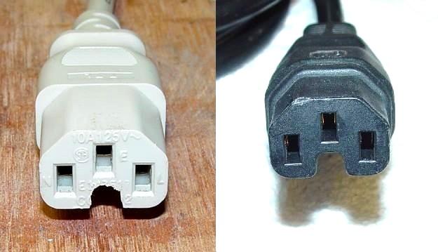
The AC input is an IEC C16 high-temperature connector. It has a nib opposite the ground terminal that prevents an ordinary power cable (IEC C13) from being plugged in. The power cable's female end (IEC C15) must have a mating notch to fit over the nib in the socket. The photo below shows this, outlined in white.
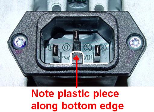
I took an ordinary computer power cable and drilled out the vinyl to create a notch so it would fit into the station's receptacle. Granted, this isn't a high-current or high-temperature cable, but for testing purposes it's good enough. The white connector on the left is the one I modified. The black connector on the right is a stock Motorola power cable.
Also on the finned side of the power supply, between the fan and the front panel, there is an input filter assembly under a perforated cover. There are two line fuses, an inrush current limiter (thermistor), and some RFI filtering components on it.
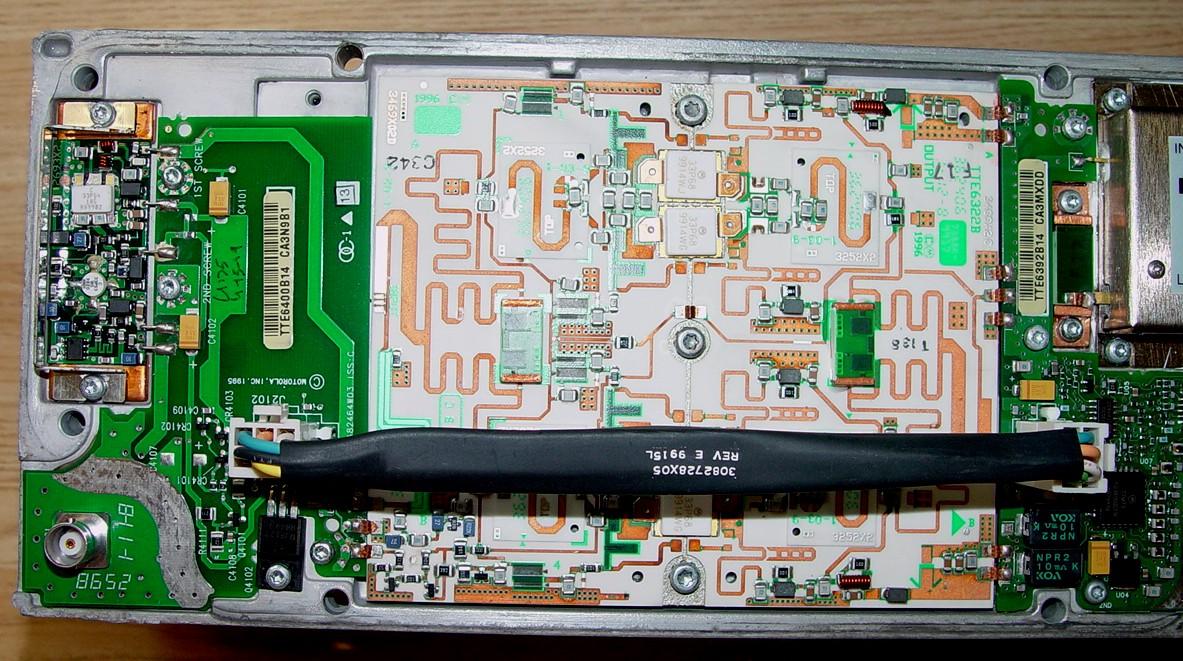
The power amplifier is very solidly built. The BNC jack on the bottom left is the input. The module at the left is the Intermediate Power Amplifier (IPA) or driver. The whitish module in the center is the actual power amplifier.
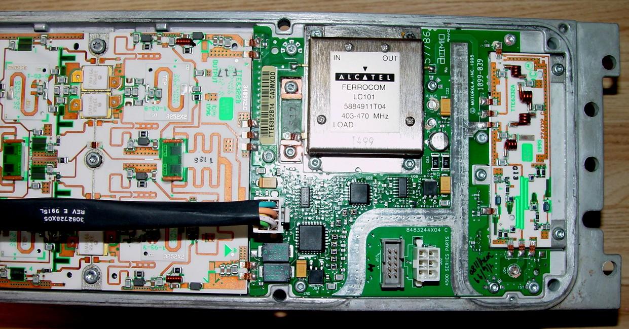
Here's the rest of the power amplifier, photo 2 of 2. The shiny box in the middle houses the single circulator. The RF Output is at the lower right corner, after a low-pass filter (necessary because of the circulator) and power sensing circuitry.
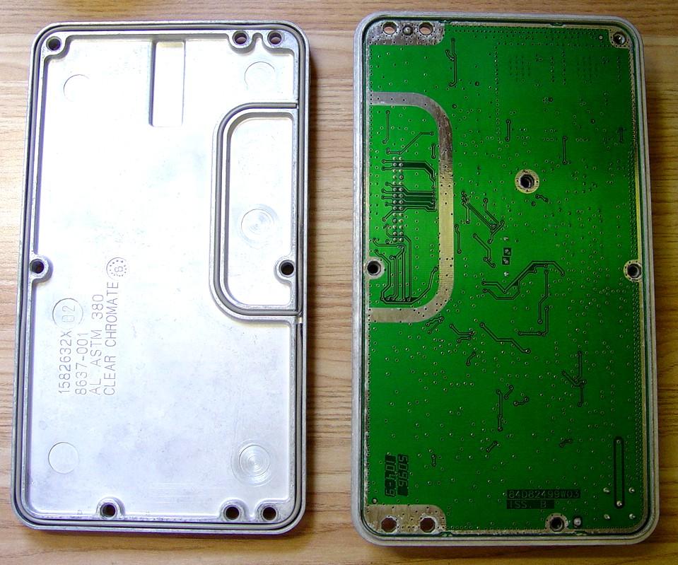
Inside the receiver module, solder side. Totally shielded.
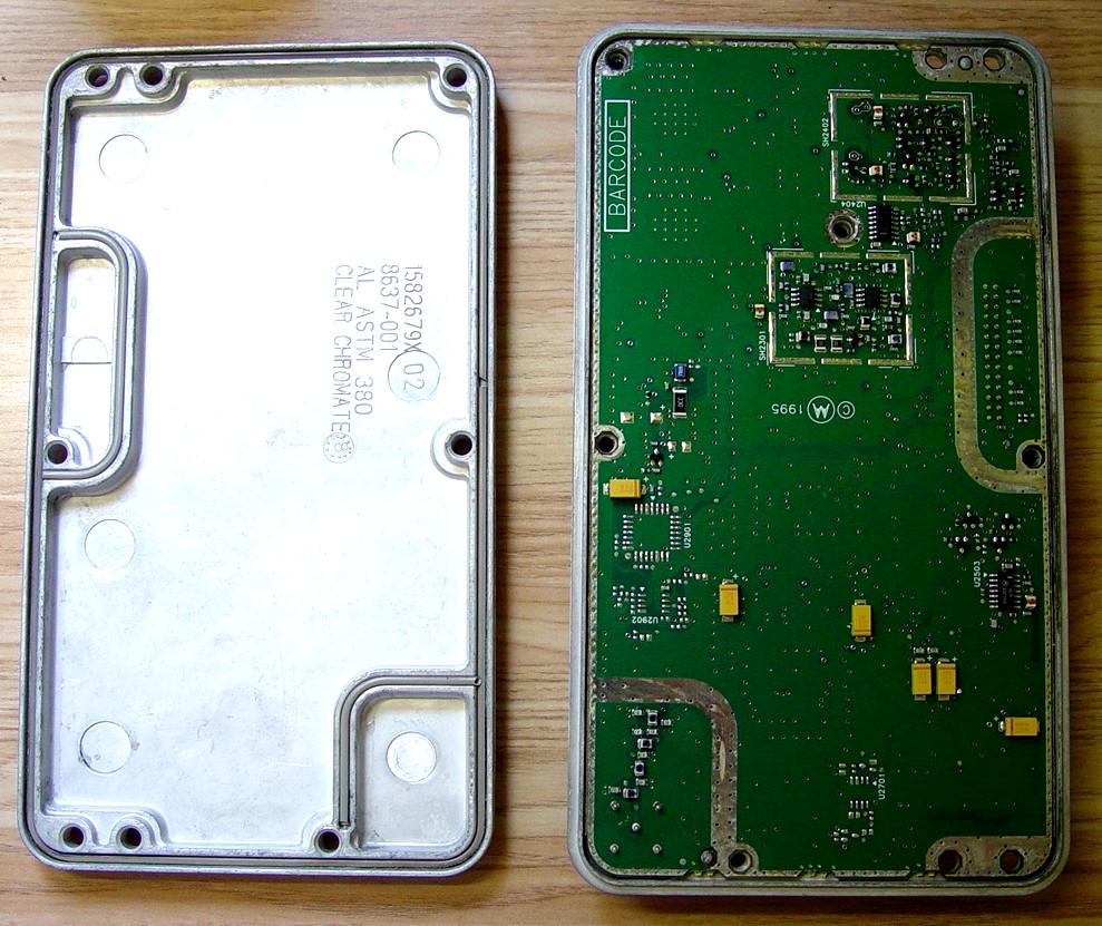
Inside the receiver module, component side. The BNC jack is the RF input. It looks like two VCOs in there. I presume the outlined areas that don't have components are tuned input stages, which are not present in this receiver, hence the necessity of the external pre-selector.
Inside the Station Control Module, solder side. Totally shielded.
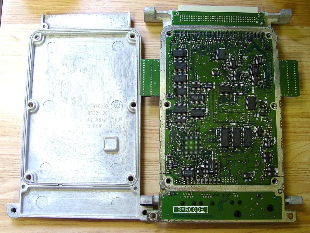
Inside the station control module, component side. This is the brains of the station. The exciter module plugs in at the left; the receiver module plugs in at the right. The SCM plugs into the backplane.
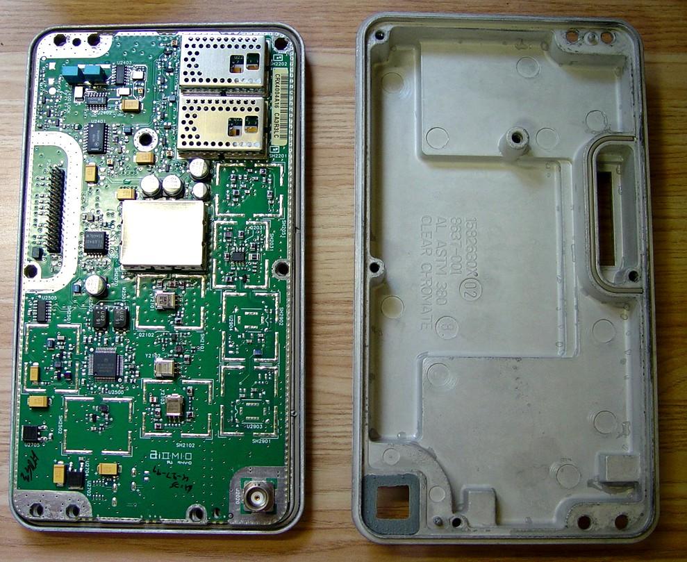
Inside the exciter module, solder side. Like the other modules, totally shielded.
Inside the exciter module, component side. The BNC jack is the RF output. Looks like two VCOs in there too.

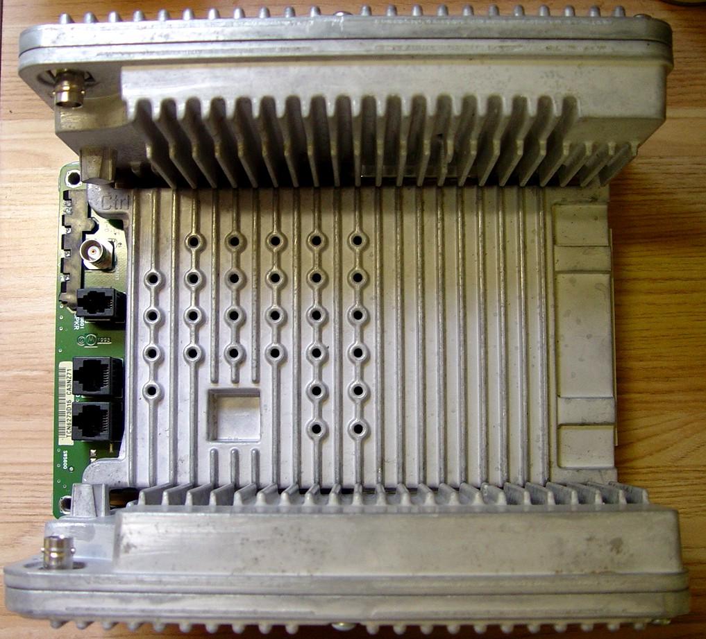
The three modules form a complete assembly that unplugs from the backplane. The front of this assembly is on the left. In this view, the exciter is on the top, the SCM is in the middle, and the receiver is on the bottom. The jacks on the front of the SCM are for an external reference oscillator (BNC), external (amplified) speaker, RJ45 programming cable (no RIB required, 3-wire RS232 cable), and a service microphone.
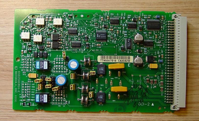
The wire-line card, standard in the MTR2000, is installed in the top slot of the card cage. This supports two or four wire remote control. An additional "Auxiliary I/O" option card can be plugged in below this one.
The UHF external pre-selector requires a special tuning probe for alignment, the same as is used by the MSF5000 and Quantar stations. The Help screen in RSS details the procedure but not the setup. It doesn't even have a diagram identifying the tuning coils. I did notice that the coil numbers are embossed into the casting; they are barely visible in the photo below. They run from left to right (closest to the RX antenna jack): 2, 3, and 4.

Credits and Acknowledgements:
MTR2000 is a trademark of Motorola, Inc.
Contact Information:
The author can be contacted at: his-callsign [ at ] comcast [ dot ] net.
Back to the top of the page
Up one level (MTR2000 Index)
Up two levels (Main Moto Index)
Back to Home
This page originally posted on 04-Jun-2011
Article text, photos, and hand-coded HTML © Copyright 2011 by Robert W. Meister WA1MIK.
This web page, this web site, the information presented in and on its pages and in these modifications and conversions is © Copyrighted 1995 and (date of last update) by Kevin Custer W3KKC and multiple originating authors. All Rights Reserved, including that of paper and web publication elsewhere.