Back to Home
Motorola Nucleus II Transmitter
By Robert Meister WA1MIK (SK)
Currently Maintained by Mike Morris WA6ILQ.
Mike knows almost nothing about this equipment so please ask on the repeater-builder mailing list!

|
Up one level Back to Home |
Adding Analog Modulation to a Motorola Nucleus II Transmitter By Robert Meister WA1MIK (SK) Currently Maintained by Mike Morris WA6ILQ. Mike knows almost nothing about this equipment so please ask on the repeater-builder mailing list! |
|
Note: Many of the photos in this article are clickable into larger images. Unless otherwise noted, all photos and images were taken by the author.
This article covers how I analyzed the equipment and added analog modulation to a digital-only Motorola Nucleus II 900 MHz paging transmitter.
The transmitter is a Motorola Nucleus II, 300-watt, continuous duty, 927 - 941 MHz with a standard control module. Mine was built in 1994. If you are lucky enough to have one with the advanced control module, the procedures discussed here may still be appropriate, since that unit can already accept analog voice audio but not PL or DPL. The standard controller, however, sends modulation to the exciter as digital data, which shifts the carrier directly (FSK), and there's no way for analog audio to pass through the controller.
There are three major sections to this article: analysis of the Nucleus exciter, analysis of the modulating radio (MaxTrac / Radius), and joining them together. I could have just written two paragraphs explaining tersely what to do, but there's no fun in that. Being the good engineer that I am, I did a lot of preparation so it would work right the first time.
Why I Bought It:
A local 900 MHz repeater using a Nucleus transmitter was having some difficulty getting DPL or PL to pass through it cleanly. Theirs had the advanced controller, but that really only allows voice audio - 300 to 3000 Hz - to pass through. Since PL is below that, and DPL is quite a bit below that, it's no wonder that they were having troubles.
When I had a chance to buy one on eBay, I did so for the following reasons:
Unfortunately, it wasn't until I was driving home with it in the back of my truck, that Dave explained to me the difference between the standard and advanced controllers, and how to tell which one I had by looking at the front panel. Luckily he had a spare user's manual for my exact unit. There's quite a lot of information in it, but nothing that I'd call technical. Service manuals, their part numbers, or schematics, are NOT available anywhere. All repairs are done at the factory; only modules are swapped in the field. This does make it a bit difficult to work on these things. I've been told that the exciter is like the one used on a Quantar, but I think the similarity ends there.
Equipment Description:
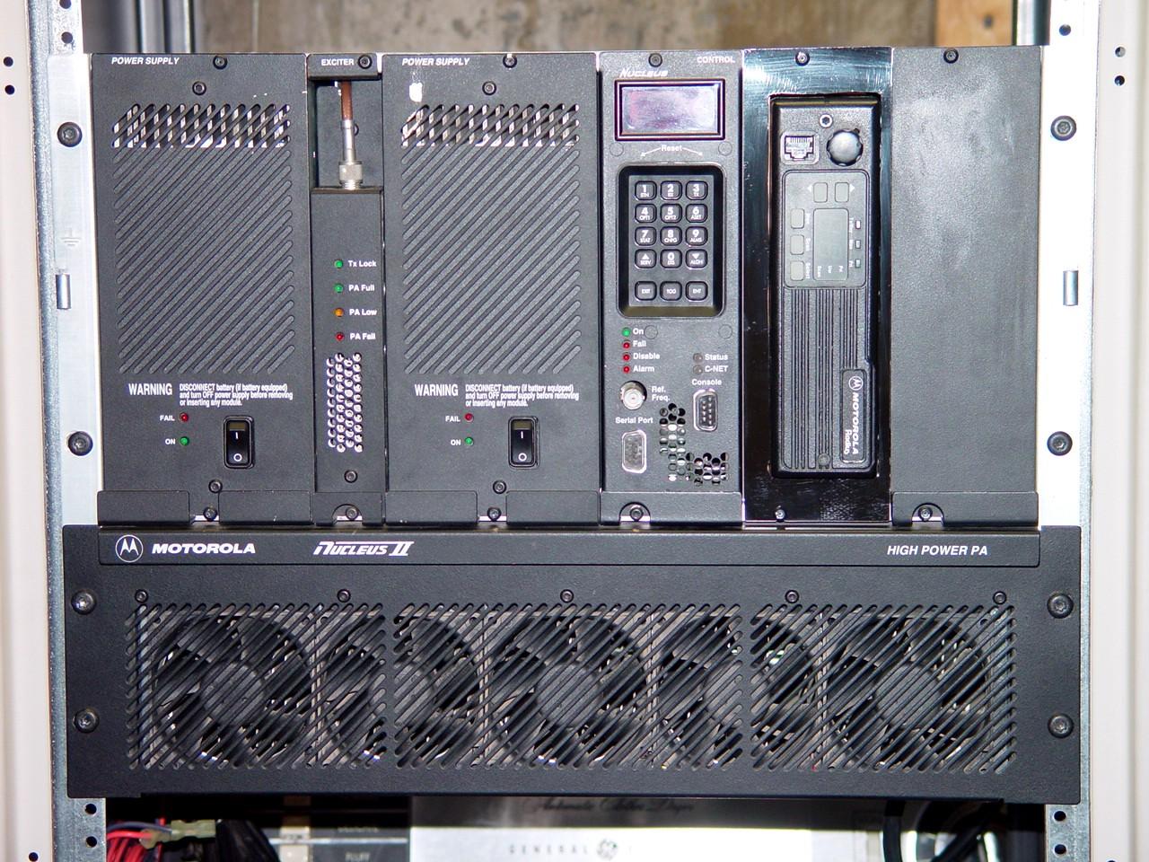
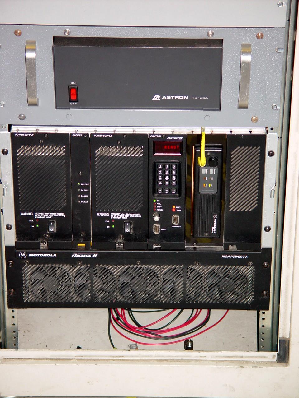
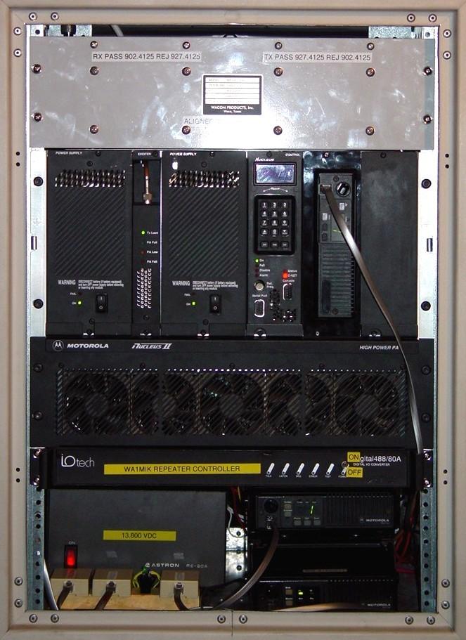
Here's my unmodified Nucleus II station in the rack next to the bench. This model is officially known as a T5482B.
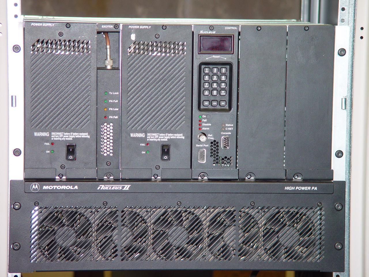
The 300-watt station chassis holds several modules. From left to right, they are: a power supply, an exciter, a second power supply, a front panel with a Station Control Module (SCM) and a Network Interface Unit (NIU) behind it, and two blank panels. The power amplifier with five fans sits below the card cage. The front panel talks to the SCM and provides a user interface for configuration, frequency, and power programming. You can also read the transmitter output power here. The NIU handles the paging protocol and provides an ovenized frequency reference. A front panel DE-9 connector on the NIU lets you set additional station parameters using a serial terminal. The blank panels cover slots for optional modules.
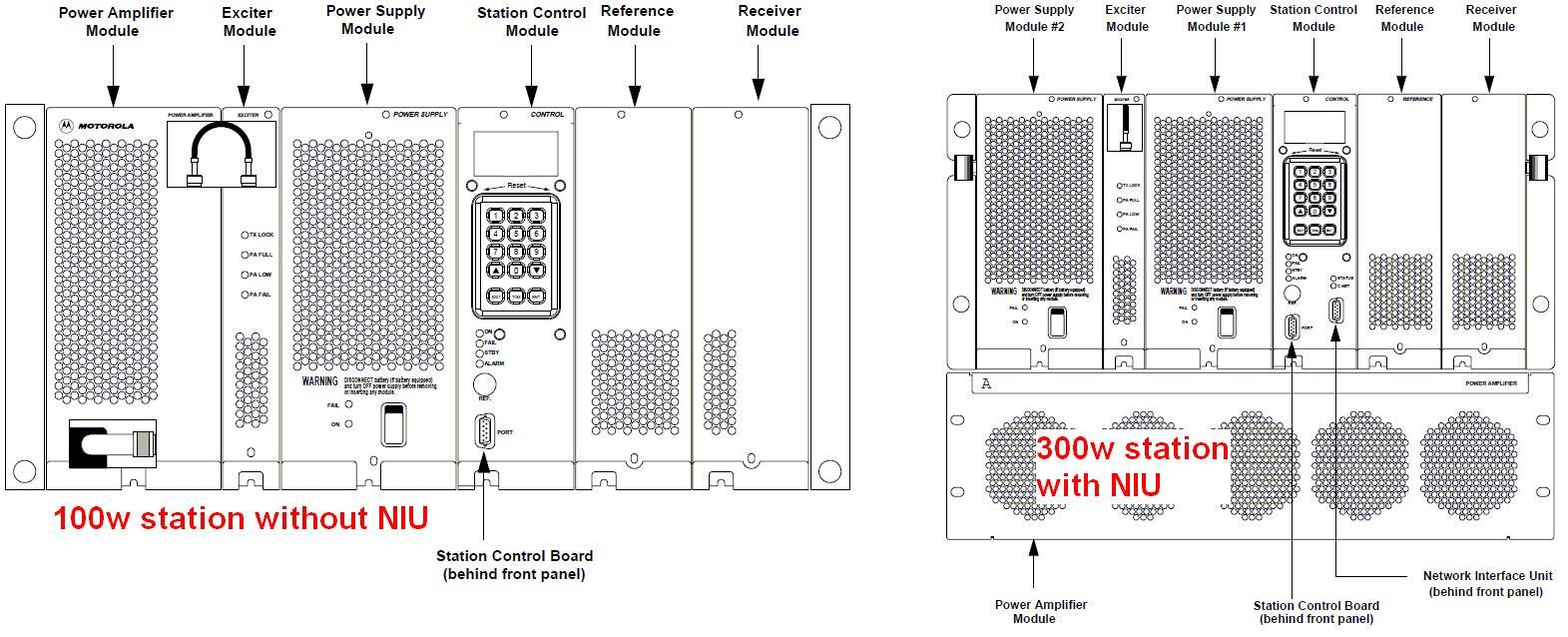
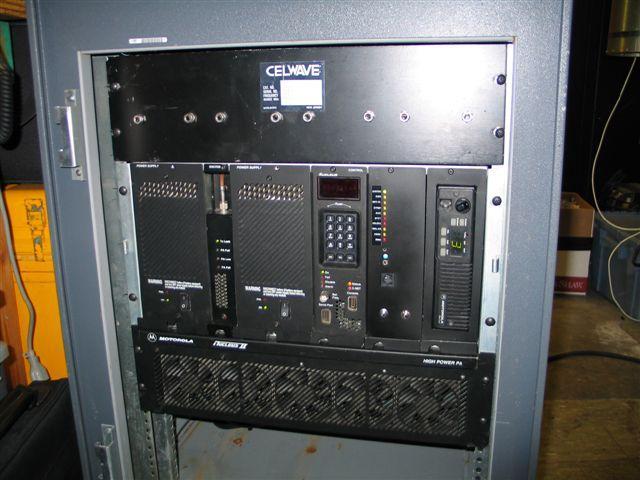
On the 100-watt station, a smaller power amplifier takes the place of the left power supply, rather than sitting below the card cage. I believe this is the primary difference between these stations. The images above show the 100-watt and 300-watt station configurations.
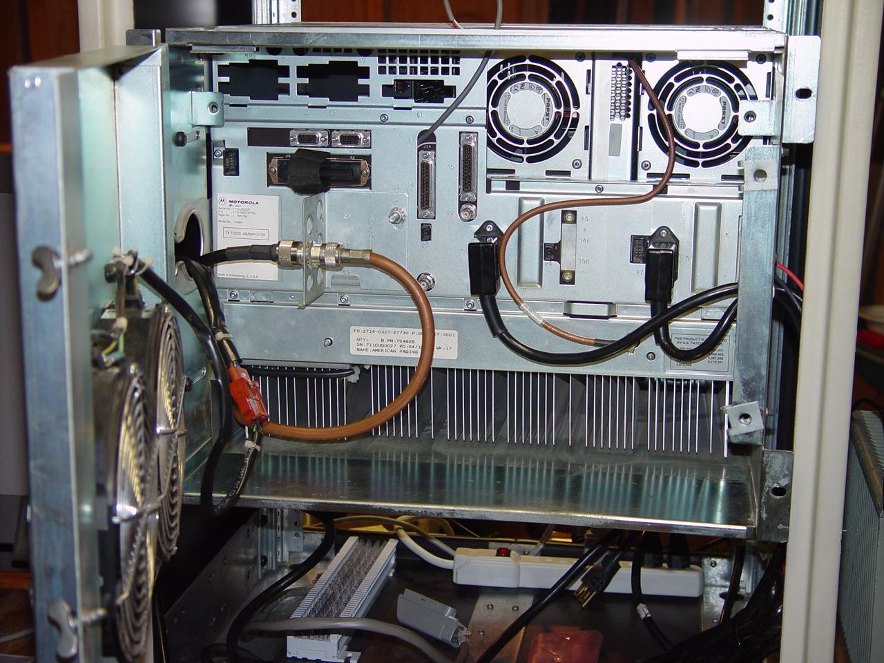
The rear panel (backplane) has a lot of connectors for options and power. A rear door holds two or four large fans that move a ton of air and make a lot of noise. The output from the power amplifier is a male N connector at the end of the tan coax. A circulator and wattmeter are built into the power amp. My station came with a T/R relay, but I replaced it with a bulkhead female N connector.
The station accepts digital paging information from a satellite receiver or network connection. There's also a modem on the NIU that can be used for diagnostics and logging. I have no idea how this all works, nor do I care to learn about it right now.
The main user interface port is a 50-pin Telco-style female connector. I obtained a mating connector and short cable with a punch-down block attached that made testing a lot easier, once I learned how to count the pins properly. One signal is called EXT KEY REQ, which will be discussed later. Another is called EXT MODE REQ. This might be a way to select different channels in the Nucleus, but I only measured 1.5 Vdc on it, and grounding it didn't change anything I could see.
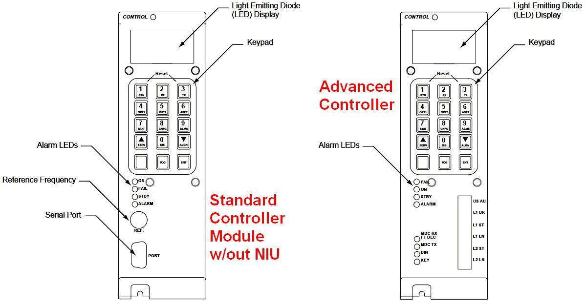
These stations come with either a Station Control Module (SCM) with or without the Network Interface Unit (NIU) or the Nucleus Advanced Controller (NAC). The image above shows the slight differences between the standard and advanced control panels.
Taking It Apart:
CAUTION: Make sure the power is disconnected from the station before removing or inserting any modules.
Each module is held in place in the card cage with two T15 Metric machine screws. The exciter is the only module that needs a cable removed before extraction. On the 100-watt stations, a short coaxial jumper feeds the power amplifier module next to the exciter; on the 300-watt stations, a long coaxial jumper runs above the exciter and connects to the rear of the power amplifier assembly. The modules just unplug from the backplane as you slide them forward.
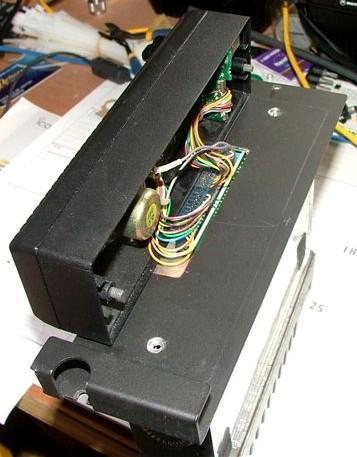
Removing the control panel gives you access to the SCM and NIU boards behind it. There's a small L-shaped piece of metal inside the bottom edge of the control panel that fits into grooves under the front edges of the SCM and NIU boards. You slip the hook from the control panel into the groove and pull on it to extract the boards. They'll be very tight if the station hasn't been apart in 10 years. After I removed mine, I sprayed the board connectors and card edges with some silicone-based spray contact cleaner (I used Channel Master Color Shield). They now go in and out a whole lot easier.
The rear of the station has a door with fans mounted on it. Mine were 120 VAC units, but the manual mentions DC fans as well. Once opened, the fans can be unplugged and the entire door can be lifted up off its hinge pins. The fan shroud is held into the back of the card cage with some T30 screws. (It's supposed to also be mounted to the rear of the outer cabinet, but my cabinet was too short for that.) Once removed, the shroud can be pulled off and set aside. Label and unplug any connectors on the rear chassis plate and move them out of your way. The battery revert cable connector, if present, is held in with two T15 screws. The rear chassis plate is held in with 11 T15 screws. Once removed, the rear chassis plate can be carefully pulled off, leaving the backplane connected to the remaining modules in the card cage. All the hardware is Metric.
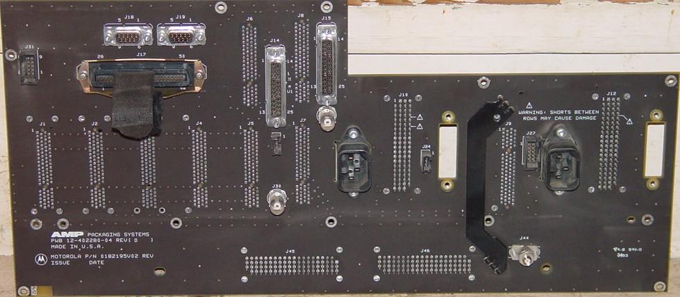
If you want to remove the backplane (not necessary for this procedure), I suggest you first unplug all the modules from the card cage, then remove the rear chassis plate. The backplane will then be held in place by only the power amplifier connectors on the 300-watt station and you can gently wiggle the backplane off of them. It's a multi-layer board with ground on both sides so you can't see any inter-connector wiring. This makes tracing circuits much more difficult. Here's what the backplane looks like behind the chassis plate.
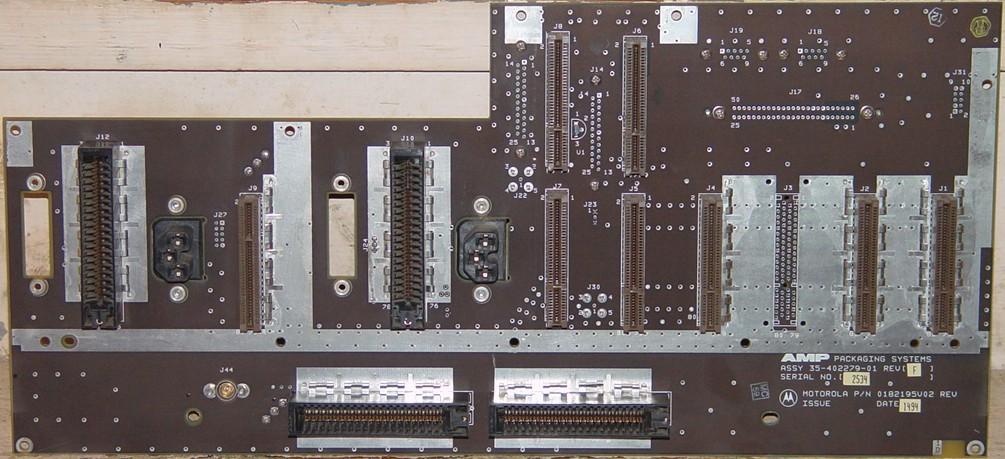
Here's what it looks like from the front of the card cage. Quite boring.
Analyzing the Nucleus Exciter:
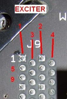
All of the backplane card edge connectors are oriented the same. Looking from the rear, each one consists of four columns of pins, arranged in two zigzag patterns. Starting at the top, pin 1 is in the upper left and pin 2 is in the 3rd column. Pin 3 is the first pin in the 2nd column, and pin 4 is the top pin in the 4th column. All the odd numbered pins are on the component side of the circuit boards, the left two columns. So the leftmost column is pins 1, 5, 9, 13, etc. The next column over is pins 3, 7, 11, 15, etc. The third column is pins 2, 6, 10, 14, etc, and the right-most column is pins 4, 8, 12, 16, etc. The last pin is 80. Once you learn the numbering scheme, it's easy to find your way. Here's a photo of the exciter's backplane connector with some of the pins labeled:
CAUTION: The electronics in the Nucleus can be damaged by static electricity. I strongly recommend that you unplug the exciter and control modules before soldering anything to the backplane.
Mark told me that modulation is present on the exciter's J9 pin 78, with ground on J9 pin 80. I soldered a piece of RG174 coax to these two pins and hooked it to my scope. The SCM can generate several test waveforms, one of which is a staircase signal, which is shown here:
I connected a 500-watt dummy load to the RF output port of the transmitter and had it generate a test signal using the SERV menu's KEY ON SYMBOL option. You can see that it's quite "digital" in nature. I learned that the DC voltage is around 4.9 VDC and the signal runs from about 3.6 to 6.2 volts. Another signal, called "00-11", is really a square wave that goes from 3.6 to 5.4 volts. This at least gave me some idea of the amplitude of the modulating signals being sent to the exciter. (Remember, this station was designed to have its carrier frequency shifted with ones and zeroes.) One of the parameters available on the control panel is called BINARY DEVIATION, and it's set to 4500 Hz. I changed it to 1000 Hz, but it had no effect on the amplitude of the modulation signals seen here.
There's an input on the 50-pin connector, J17 pin 10, called EXT KEY REQ (external key request). This can be configured for active high or active low. I've set it for active low; grounding it will cause the transmitter to key up and emit RF power. It takes about 200 mADC to pull this line low from 5 VDC, and it must be pulled significantly below 1 volt. I surmise that the high current is present to keep relay contacts clean.
Modifying the Nucleus:
It was now time to make an invasive cut into this unit. Mark told me that the modulation signal comes from the SCM, J7 pin 60, which I verified with an ohmmeter. The circuitry on the SCM is a low impedance driver, so it must be disconnected before external audio is applied. This pin is on the solder side of the SCM, right below the gap in the lower card edge connector. I just used a sharp utility knife to make two shallow cuts and remove the foil between them. This makes it easy to repair if necessary. This is the ONLY modification to the Nucleus. The picture below shows where this is located.
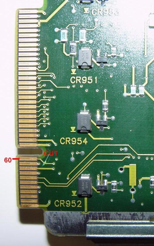
It may be possible to solder an appropriate value resistor across this cut, and have the internal controller still provide digital modulation while you add external PL to the same line. As I had no need for this capability, I did not experiment with it further.
Analyzing the Exciter Modulation:
I connected a frequency counter to a tap at the dummy load attached to the RF output. I could now apply my own stimulus to the exciter without the SCM getting in the way. I keyed the transmitter using the external key request line, although the KEY ON SYMBOL method from the front panel would work as well, since there's no longer any internal modulation capability.
I measured the idle voltage at the exciter J9 pin 78 as 5.03 VDC and noted the carrier frequency, which I had previously programmed to 930.00000 MHz for convenience. I hooked the exciter modulation input line to a variable DC power supply and ran the voltage from 3 to 7 volts; there was no effect on the carrier frequency, so I deduced that the modulation input is AC-coupled. I then applied a signal from my function generator through a 470 uF capacitor for DC-blocking. A true RMS voltmeter measured the input level. I applied sine wave signals of various frequencies and amplitudes, and monitored the results on a deviation meter now attached instead of the frequency counter. The results are noted below.
| Input Vrms | Deviation in kHz |
|---|---|
| 0.148 | 1 |
| 0.324 | 2 |
| 0.508 | 3 |
| 0.686 | 4 |
| 0.862 | 5 |
| 1.031 | 6 |
| 1.193 | 7 |
I then set the input level for 3.0 kHz deviation (0.508 Vrms) and varied the frequency. The following table summarizes the frequency response of the exciter.
| Frequency in Hz | Deviation in kHz |
|---|---|
| 10 | 1.2 |
| 15 | 2.3 |
| 20 | 3.6 |
| 30 | 4.2 |
| 50 | 3.4 |
| 100 | 3.0 |
| 200 | 3.0 |
| 400 | 3.1 |
| 800 | 3.0 |
| 1000 | 3.0 |
| 2000 | 3.0 |
| 3000 | 3.0 |
| 4000 | 3.0 |
| 5000 | 2.9 |
| 6000 | 2.8 |
| 7000 | 2.7 |
| 8000 | 2.6 |
This is what it looks like graphically.
The exciter modulation input line draws 0.2 mA-RMS with a 1 kHz, 1 V-RMS signal, which makes the input impedance around 5000 ohms. The current was a bit lower above 5000 Hz.
I ran additional data using a 1 kHz tone.
| Input Vrms | Deviation in kHz |
|---|---|
| 0.05 | 0.6 |
| 0.10 | 0.8 |
| 0.15 | 1.1 |
| 0.20 | 1.4 |
| 0.25 | 1.6 |
| 0.30 | 1.9 |
| 0.35 | 2.2 |
| 0.40 | 2.5 |
| 0.45 | 2.7 |
| 0.50 | 3.0 |
| 0.55 | 3.3 |
| 0.60 | 3.6 |
| 0.65 | 3.9 |
| 0.70 | 4.2 |
| 0.75 | 4.4 |
| 0.80 | 4.7 |
| 0.85 | 5.0 |
| 0.90 | 5.3 |
| 0.95 | 5.6 |
| 1.00 | 5.9 |
I connected my spectrum analyzer with FM demodulator to the sampling port at the output of the transmitter and repeated the deviation measurements at 1 kHz.
| Input Vrms | Deviation in kHz |
|---|---|
| 0.00 | 0 |
| 0.18 | 1 |
| 0.36 | 2 |
| 0.54 | 3 |
| 0.72 | 4 |
| 0.90 | 5 |
It really is that linear, as the graph below shows.

As a final test, I changed the waveform with the amplitude set for 0.36 V-RMS. I did this at two frequencies. The function generator kept the RMS voltage constant, however the different waveforms produced vastly different deviation levels. The results are shown below.
| Waveform | 1000 Hz | 50 Hz |
|---|---|---|
| Sine | 2.0 kHz | 2.5 kHz |
| Square | 1.5 kHz | 2.1 kHz |
| Triangle | 2.2 kHz | 3.0 kHz |
The spectrum analyzer captured these images during this test.
1 kHz sine wave
1 kHz square wave
1 kHz triangle wave
50 Hz sine wave
50 Hz square wave
50 Hz triangle wave
My conclusion from all of this testing is that the Nucleus exciter is relatively flat with sine wave input, from 50 to 5000 Hz. There is some low frequency increase, and the square wave response below 50 Hz tends to round off the top and bottom of the waveforms. There was no visible distortion on any of the testing I performed except for low-frequency square waves. The modulation input sensitivity is about 180 mV-RMS per 1 kHz deviation at the input to the exciter. I can key the transmitter by grounding the EXT KEY REQ line.
Feeding the Nucleus:
So now I know what the Nucleus expects for input signals... All I need now is a properly conditioned audio signal to feed into it.
One of my goals was to have a properly working PL or DPL signal. I could go buy a ComSpec PL or DPL board and hook that up. The transmitted audio also needs to be filtered (300 - 3000 Hz) so it doesn't interfere with the PL/DPL signal, limited, clipped, and pre-emphasized, because the Nucleus exciter has a flat response. I'll have to mix the PL/DPL signal and the voice audio together in the proper ratio, and provide some kind of gain control. Finally, I need some way to key the Nucleus for the duration of the PL or DPL signal, including the reverse burst or turn-off code. This is quite a lot of circuitry. Maybe the wheel has already been invented.
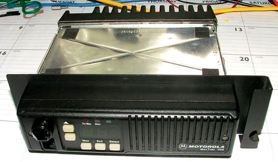
MaxTrac to the Rescue:
Motorola MaxTracs (and Radiuses) are fine little radios. They're capable of generating PL (with reverse-burst) or DPL (with turn-off code), and have all the required audio processing necessary to do the job. The logic board does all of this for its own modulation of the RF board. Let's see what's available inside the radio.
All the audio work is done on the logic board. The microprocessor generates PL or DPL using a two-bit digital-to-analog converter (a pair of resistors) and some filtering. This same microprocessor generates reverse-burst (for PL) or the turn-off code (for DPL) and keeps the radio transmitting during this time. The microphone audio runs through a high-pass filter to keep low frequency audio away from the PL tones. A limiter keeps the instantaneous deviation under control. A voltage-controlled amplifier allows the gain to be controlled via the microprocessor and another D/A converter. The tone/voice ratio is preset by the board's components. Pre-emphasis is provided as well. Everything I need is right here, and then some.
Almost any MaxTrac or Radius model can be used for this project. The number of channels or output power doesn't matter. 900 MHz radios, however, seem to have a lower audio signal than those on other bands, possibly because the deviation is usually 2.5 kHz instead of 5.0 kHz. There IS a substantial difference in the final transmit audio circuitry, so for now, stick to any VHF, UHF, or 800 MHz model. Use whatever you have handy... it does not even need a functioning receiver or PA deck. The best unit would be a two-channel 15 watt 800 MHz radio that can NOT do talk-around - if it did, you'd have converted it to be used as a 900 MHz receiver by now! (See my companion article in the MaxTrac section of this web site.) All we really need is the logic board and part of the front panel. The radio will operate without the RF board or the power amplifier.
Analyzing the MaxTrac Modulation:
I hooked an 800 MHz MaxTrac to a dummy load and modulation analyzer, plugged in a microphone, hooked a scope and voltmeter to pin 10 of the connector that goes between the logic board and the RF board (the signal is labeled VCO MODULATION), programmed several channels into the radio with PL and DPL, and started measuring.
| Signal | Dev. Pot | Volts AC | Volts p-p | Deviation in kHz |
|---|---|---|---|---|
| Loud Whistle | 40 | 0.450 | 1.18 | 4.9 |
| 100.0 Hz PL | 40 | 0.081 | 0.27 | 0.9 |
| 311 DPL | 40 | 0.102 | 0.27 | 1.2 * |
| Loud Whistle | MAX | 0.693 | 1.80 | 8.6 |
| 100.0 Hz PL | MAX | 0.116 | 0.35 | 1.3 |
* The DPL deviation is inaccurate due to the composition of the signal.
The MaxTrac service manual says there should be 1.1 Vp-p with a specific input signal, so things are looking good. The maximum available audio of 0.693 VAC should be able to provide almost 4 kHz of deviation on the Nucleus. Recall that the exciter's sensitivity is about 180 mV per kHz. Since the 900 MHz band is running 2.5 kHz, I only need about 0.45 VAC of audio. By a lucky coincidence, that's exactly what the MaxTrac is giving me.
Next, I connected an audio oscillator to the MIC input through a 100 uF capacitor and set the level for 50 mVp-p. I chose this level because it did not cause limiting to occur at any test frequency due to pre-emphasis. There was no PL or DPL generated by the radio. The following table shows the transmitter audio pre-emphasis effect, which should be about 6 dB per octave increase.
| Frequency in Hz | Deviation in kHz |
|---|---|
| 100 | 0.200 |
| 200 | 0.400 |
| 300 | 0.570 |
| 400 | 0.720 |
| 500 | 0.860 |
| 600 | 1.000 |
| 700 | 1.140 |
| 800 | 1.280 |
| 900 | 1.410 |
| 1000 | 1.540 |
| 1100 | 1.670 |
| 1200 | 1.810 |
| 1300 | 1.940 |
| 1400 | 2.070 |
| 1500 | 2.200 |
| 1600 | 2.320 |
| 1700 | 2.440 |
| 1800 | 2.580 |
| 1900 | 2.700 |
| 2000 | 2.830 |
| 2100 | 2.940 |
| 2200 | 3.050 |
| 2300 | 3.160 |
| 2400 | 3.240 |
| 2500 | 3.320 |
| 2600 | 3.370 |
| 2700 | 3.400 |
| 2800 | 3.410 |
| 2900 | 3.380 |
| 3000 | 3.320 |
| 3100 | 3.240 |
| 3200 | 3.130 |
| 3300 | 2.980 |
| 3400 | 2.830 |
| 3500 | 2.670 |
| 3600 | 2.510 |
| 3700 | 2.340 |
| 3800 | 2.180 |
| 3900 | 2.040 |
| 4000 | 1.900 |
Here's the graphical view:
I measured the distortion at various deviation levels using 400 and 1000 Hz tones, again without PL or DPL. My modulation analyzer only measures distortion at these two frequencies.
| Deviation in kHz | 400 Hz Dist% | 1 kHz Dist% |
|---|---|---|
| 0.5 | 2.2 | 2.3 |
| 1.0 | 1.0 | 1.1 |
| 1.5 | 0.7 | 0.7 |
| 2.0 | 0.5 | 0.6 |
| 2.5 | 0.4 | 0.4 |
| 3.0 | 0.4 | 0.4 |
| 3.5 | 0.3 | 0.3 |
| 4.0 | 0.3 | 0.7 |
| 4.5 | 10.6 | 10.4 |
The slight increase for the 1000 Hz tone at the 4 kHz deviation point is due to pre-emphasis raising the audio amplitude.
Well, what's left to measure? Let's see what the actual MIC jack input sensitivity is for this radio. I fed in a 400 Hz tone and checked the results.
| Input mVrms | Deviation in kHz | Distortion Percent |
|---|---|---|
| 0 | 0 | - - - |
| 20 | 0.400 | 2.68 |
| 40 | 0.770 | 1.34 |
| 60 | 1.140 | 0.84 |
| 80 | 1.530 | 0.66 |
| 100 | 1.910 | 0.53 |
| 120 | 2.280 | 0.46 |
| 140 | 2.650 | 0.40 |
| 160 | 3.020 | 0.35 |
| 180 | 3.400 | 0.30 |
| 200 | 3.790 | 0.29 |
| 220 | 4.150 | 0.29 |
| 240 | 4.360 | 2.56 |
| 260 | 4.440 | 7.12 |
| 280 | 4.500 | 11.2 |
| 300 | 4.530 | 15.0 |
Based on this test, the recommended MIC input audio level should be below 240 mVRMS for maximum clean deviation. The MaxTrac manual says 80 mVRMS should produce 60% of the maximum deviation, i.e. 3 kHz. My results were somewhat different.
Other MaxTrac Signals:
I measured the signals on all of the logic/RF interconnection pins, in both receive and transmit. These are summarized below.
| Pin # | Function | VDC | mVAC | Transmit |
|---|---|---|---|---|
| 1 | +9.6VDC | 9.649 | 0.18 | 9.649 VDC |
| 2 | Carrier Detect = Low | 3.9525 | 0.2 | --- |
| 3 | Receive Audio | 2.3460 | 47+ | 2.3460 VDC |
| 4 | T/R Shift T = Low | 9.650 | 0.2 | 0.1 VDC |
| 5 | VCO Lock Detect = Low | 0.0465 | 0.492 | --- |
| 6 | Synthesizer Data | 5.0587 | 1.730 | --- |
| 7 | Synthesizer Clock | 0.0007 | 1.725 | --- |
| 8 | Synthesizer Chip Enable | 0.0005 | 1.794 | --- |
| 9 | Frequency Control | 5.615 | 0.6 | --- |
| 10 | VCO Modulation | 4.8562 | 0.0 | 0.5 VAC |
| 11 | Ground | 0.0000 | 0.0 | 0.0000 VDC |
| 12 | VCO Shift Line | 0.7189 | 0.0 | 0.7189 VDC |
| 13 | Reference Modulation | 4.2627 | 1.050 | 1.7 VAC |
| 14 | Temperature Sensor | 2.85 - 2.94 | 0.340 | 8.4 VDC |
I then pulled the RF board out of the radio and measured the pins again. Items being supplied from the RF board (pins 2, 5, 14) had nothing of interest on them. In receive mode, all of the front panel LEDs and functions worked normally, except there was no demodulated audio from the RF board, so the BUSY LED flashed all the time. The MON button would still toggle the MON LED and pressing any button would emit a beep from the speaker. With no receiver, there was also no squelch noise. Most of the other lines sat where they were, except the T/R shift line went to ground. Modulation audio appeared on pins 10 and 13. When I plugged in a microphone, the MON LED went out and the MON button would cycle through the three states.
When I pressed the PTT button, the radio's red transmit LED lit up. The radio drew 2 amps of current, but then dropped to 0.5 amps after a second or two. If I held the center pin of the transmit coax feeding the PA to ground, this current rise did not occur. I flipped the radio over and noted that the controlled B+ voltage to the PA started at +13.8, then dropped to 0.0 after a second or two, so this tells me the microprocessor was shutting down the PA and causing the current to drop. If I had programmed the output power to zero, I think the current would have stayed low all the time.
The radio stayed in transmit mode as long as I held the PTT button. Apparently it didn't care too much about not having an RF board present, which also meant no temperature compensation or synthesizer lock voltage. I guess they aren't too important on an 800 MHz radio.
I fed an audio signal into the Receive Audio pin. It was quite sensitive, as in 30 to 40 mVAC. I got plenty of controllable audio out of the front panel loudspeaker.
Note that there's nearly 4.9 VDC on the VCO Modulation line (pin 10). This matches very nicely with the DC voltage on the Nucleus exciter input. No coupling capacitor is needed since the exciter is AC-coupled.
Modifying the MaxTrac:
I didn't have any MaxTracs available, so I used a UHF Radius instead. These have the same boards inside, but different labels outside. They also use a different RSS. For this project, they are interchangeable.
The T/R signal available on the logic board is high on receive and low on transmit. I thought about using this signal through a diode to drive the Nucleus directly, but if the radio should lose power, this line could inadvertently key the Nucleus, so I discarded this idea. As I later found out, the EXT KEY REQ input requires 200 mA to pull it to ground, so I did need something else to key it up.
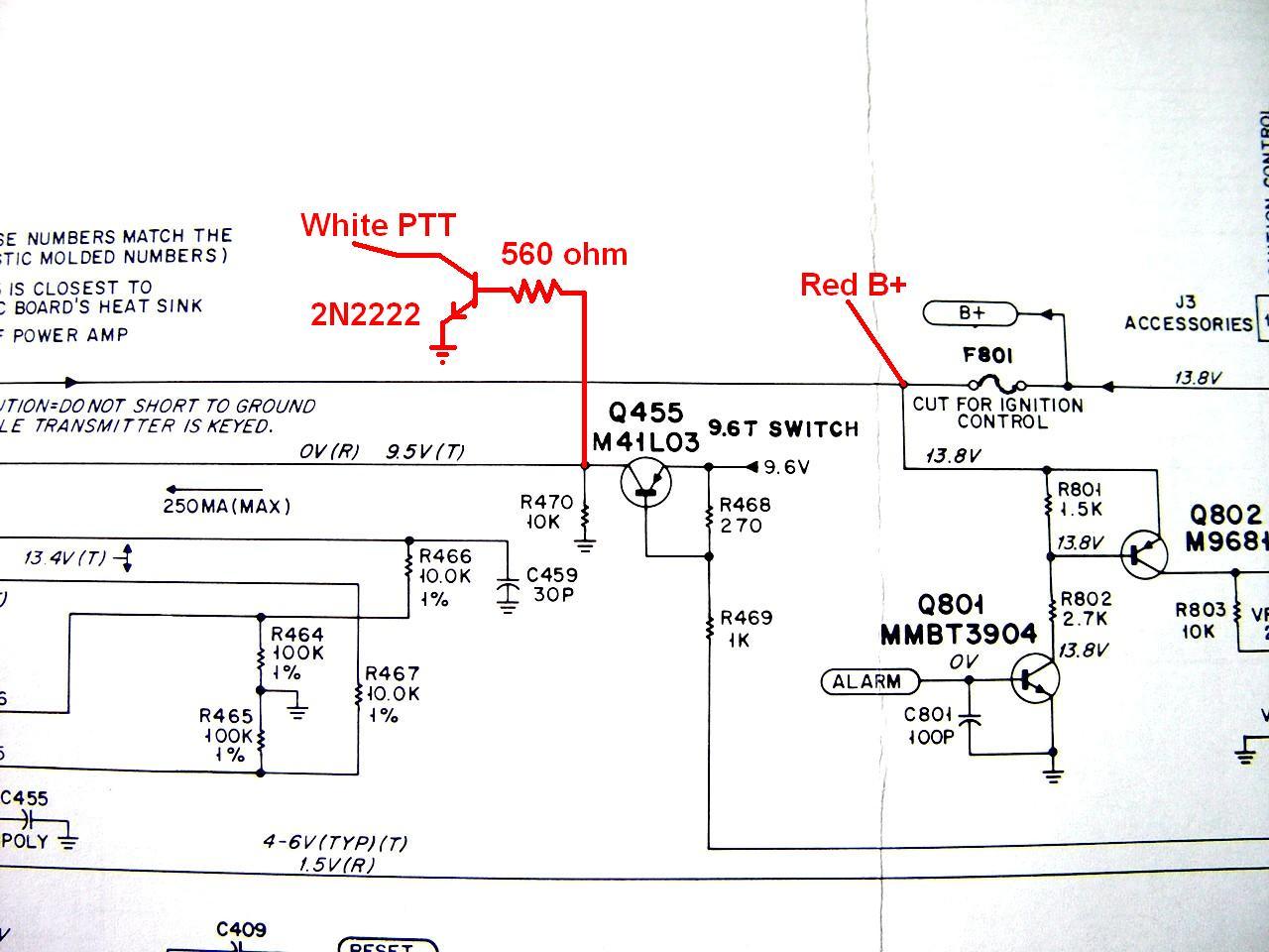
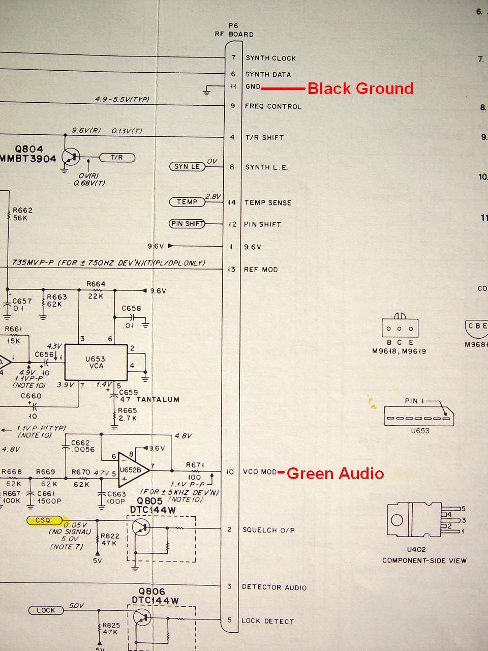
I built my own PTT circuit. It consists of a 560-ohm resistor from the collector of Q455 (this feeds the power amplifier connector pin 1), which goes to +9.6 Vdc on transmit. The other end goes to the base of a 2N2222 (or any other common NPN) transistor. The emitter goes to ground - I found a conveniently located hole in the logic board that was labeled GND so I used that. The collector of this transistor now becomes the PTT line coming out of the radio. When the radio is transmitting, the transistor turns on and the collector will pull the EXT KEY REQ line to ground very nicely. (Initially I used a 5.6k resistor, but that didn't provide enough drive current and the transistor would only pull the EXT KEY REQ line down to 1 volt. These transistors have a current gain of around 100, and the 1.7 mA base current just wasn't enough to turn the transistor on fully. It now gets 17 mA base current, the transistor fully saturates, and the EXT KEY REQ line gets pulled down to 0.2 VDC.) The schematic segment below shows this circuit.
These radios are very well sealed. The only available openings are too small to bring wires through. I decided to remove the power amplifier. This reduces the weight of the radio and eliminates its ability to generate heat. It also gave me some chassis slots through which I fed my wires. Of course, this means you can no longer use a normal MaxTrac power cable, but once the radio is installed in the Nucleus, you won't need to worry about that. If you choose to leave your power amplifier attached, you'll have to leave the bottom cover off the radio to bring the wires through, or cut a notch in the cover.
Note from WA6ILQ: An alternative, if you want to use the MaxTrac power cable, is to check out the hanging tag rack at the local auto parts store. Locally here in Los Angeles one of the common items is a 1-foot "extension cord" with MaxTrac-power-plug style connectors on both ends. One of these could be purchased for about $4, one end cut off and the remaining pigtail wired into the MaxTrac chassis. The wire size is not large enough to run a MaxTrac transmitter with the PA deck operating, but in this particular case you are pulling very minimal current.
I also removed the accessory plug and added a small jumper to pins 15 and 16 to enable the internal loudspeaker. If you have a radio with a 5-pin logic board, you don't have to worry about this.
I used about two feet of Belden 8723: two individually shielded pairs of #22 wire with one bare ground lead. P6 is the interconnection to the RF board. I wired the cable up as follows:
| Color | Connection | Function |
|---|---|---|
| RED | Front of JU801 | +14 VDC |
| BLACK | P6 pin 11 | GROUND* |
| WHITE | Transistor Collector | PTT Output |
| GREEN | P6 pin 10 | Audio Output |
* Not visible in the photo is that the shield of the cable is tied to the black wire under the heat shrink.
The PTT and power signals were shown in a previous schematic. The audio and ground connections are made on the inter-board connector, shown here:
I measured the DC current that the radio draws: 5 mA when turned off (standby current for the microprocessor); 300 mA in receive; 400 mA in transmit. Each of the front panel LEDs or segments draws about 11 mA, so the current varies as you change channels.
I could have removed the RF board as well, as the logic board seems to work just fine without it. I also could have pulled the front panel off and just kept the volume control and MIC jack piece, but then I'd have to mount it.
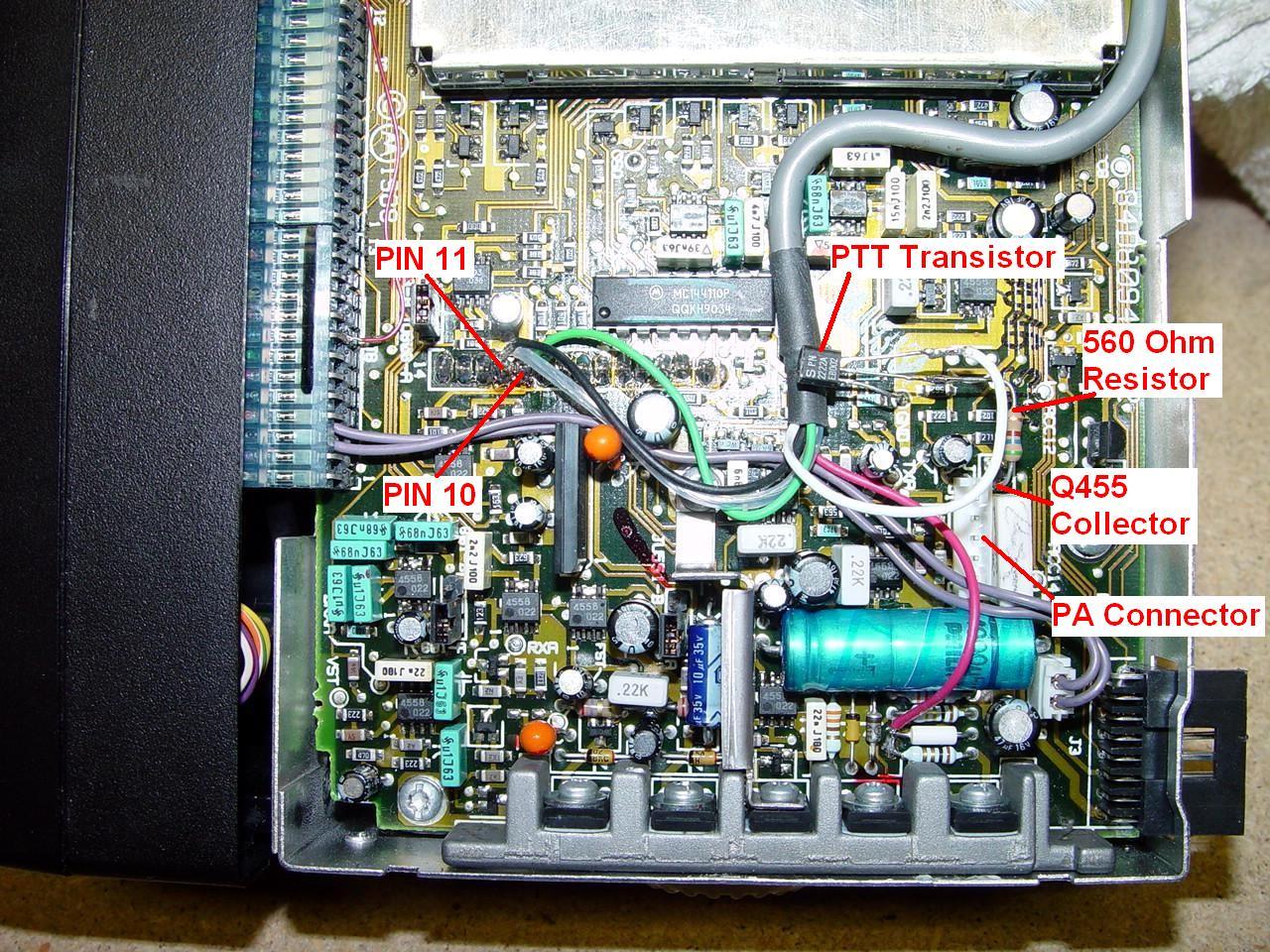
My radio had the HLN9313 logic board, and the schematic and pictures in this article are for that board. If you have a different board, you may need to hunt around to find the appropriate spots for the B+ and PTT signals. One alternative is to solder directly to the power amplifier connector on the logic board. Pin 1 of that connector goes to Q455's collector, where I picked up the 9.6V on transmit to feed the base of the PTT transistor I added. Pin 5 of the PA connector is the B+ input from the DC connector on the back of the power amplifier and it feeds the point where I attached my red power wire. Life would be much simpler if all of these radios used the same logic board.
Programming the MaxTrac:
You must set the transmitter power output to 00. You should set the transmitter deviation to around 40. You will need to enter receive and transmit frequencies. Pick something that's not likely to cause interference anywhere. The RF board will try to transmit, but the power amplifier (if it's still present) won't put out any power. If you've removed the RF board, the frequency is unimportant as long as it's acceptable to the radio you're using. In a sensitive environment, this will insure no spurious emissions. Choose the proper PL / DPL tone; set it on both transmit and receive. Set the transmitter timeout to 000. If the radio is a two-channel model, program both channels the same. If it's a multi-channel radio, delete all but channel 1 and just program that one. The reason for doing this is that the radio may not power up on the same channel it was when power was removed. There's no source of constant power to maintain the radio's memory. If all channels are the same, it won't matter how it comes up.
You could program several channels on the radio and change them remotely. This would allow you to select several different PL or DPL codes, or none at all. Most MaxTracs and Radiuses have no provision for remote channel selection, however. Later models have a feature called "Channel Steering". I leave this part of the exercise to the reader.
I went through the logic board replacement procedure and set all the deviation soft-pots to about 2/3rd of full scale. I have not fine-tuned the PL, DPL, or total deviation settings.
Hooking It Up:
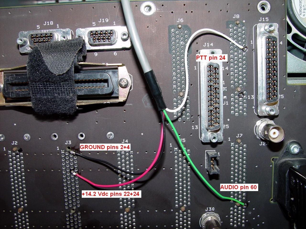
I used a 6-contact, 0.062 inch Molex connector to allow me to disconnect the radio from the Nucleus. It also let me attach the wires to the backplane, then put the rear chassis plate back on. The connector is small enough to fit through any of several openings; I chose to route my cable over the top of J14 but it can also be run to the left of J18. It's about 1 foot of Belden 8723. (After I mounted the radio in the Nucleus, I found that it would have been more convenient to use two feet of wire here, so the connector would be accessible from the front of the Nucleus. With the shorter cable, you can reach the connector from the front, but it's really meant to be handled from the back of the chassis.)
I used a piece of heat-shrink tubing over the end of the jacket to keep the unused shield and ground foils from shorting anything out. The cable's shield was connected to the BLACK wire at the radio and the BLACK wire on both Molex connectors.
I found that position J3 did not have a connector installed in the backplane. Pins 2 and 4 are a good place to pick up ground; I soldered my black wire directly to those two holes. Pins 22 and 24 have +14.2 VDC; I soldered my red wire directly to those two holes.
The EXT KEY REQ signal from J17 pin 10 was traced to the SCM where it can be found on J8 pin 24; I soldered my white wire directly to that pin.
We already know that the exciter's modulation input (J9 pin 78) comes from the SCM at J7 pin 60; I soldered my green wire directly to that pin.
This picture shows the connection points on the backplane.
I built a C-shaped bracket/tray using 1/2-inch plywood, eight inches tall, to hold the radio firmly in the Nucleus. Two M5x10x0.80 screws hold the radio in the bracket (the threaded holes for the mobile bracket are metric). Another piece of plywood prevents the radio from sliding back. The radio's control head protrudes about 1/2 inch from the card cage.
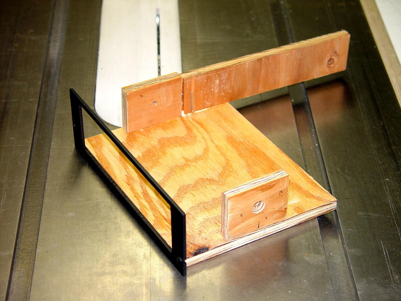
I cut a piece of smoked Lexan to fit the opening, rounded the corners, traced the control head dimensions on it, and cut the center out. A bit of spray paint on the back makes it opaque. It might have looked better if I had used some 1/16-inch sheet metal, but I have a basement full of woodworker's tools, and "I don't do metal." Here's the finished product:
You could remove the other blank panel, alter the mounting arrangements, and put in a second converted MaxTrac for use as a repeater receiver. While you're at it, you might as well put the repeater controller inside too - there's plenty of space in the card cage - and most are a lot smaller than a MaxTrac. You can easily pass a length of RG58-size coax (for the receiver antenna) through openings in the rear chassis plate above the backplane.
Nucleus Configuration:
You will need to tell the Nucleus to use the EXT KEY REQ input and it will be active LOW. To do this, gain access to the system if necessary (i.e. enter the password) and press the CNFG button. Press the up-arrow button once to reach the menu choice SPECIAL KEY SELECT, press ENTER, then press the up-arrow button twice to reach EXT LOW. Press ENTER to select this choice, then press EXIT several times to get out of the menu.
The station is capable of storing 20 frequencies. I could manually enter and select another channel, but it always used channel 1's frequency and reverted back to it when I keyed it using the EXT KEY REQ input. I'm just going to have to live with that.
Remember I mentioned that BINARY DEVIATION setting at the beginning of the article? Well, it still has no effect on the resulting deviation whether it's set to 4500 or 1000. I wish there was more technical information publicly available for these units.
Final Tests:
I programmed the Radius for 455.00000 MHz receive and transmit (it might be better to put it into the amateur band when I start seriously using it), and entered various PL, DPL, and carrier encoding values. This allowed me to change them easily while listening on another similarly programmed radio.
I connected my spectrum analyzer to the signal tap at the dummy load. The vertical sensitivity is 1 kHz per division. The horizontal varied as I measured different signals. I used the analyzer's min/max peak search function to find the highest and lowest peak values; this produces the peak-to-peak deviation values that I've shown in the following text. Note that a deviation meter only shows the PEAK deviation, which would be exactly half of the values indicated here.
PL tones of 67.0, 100.0, and 192.8 Hz were completely inaudible and are causing the transmitter to deviate approximately 1.0 kHz peak-to-peak.

DPL code 311 is completely inaudible and causes the transmitter to deviate about 2.13 kHz peak-to-peak. The waveform is by no means a square wave, but it is going through the Nucleus and it does work, but the receiving radio sometimes takes longer to decode it than for PL.
I sent signals from my function generator into the microphone jack and observed the results on my spectrum analyzer. A 500 Hz sine wave at 110 mV-RMS just started to limit on the peaks and resulted in approximately 4.5 kHz peak-to-peak.
A 500 Hz sine wave at 240 mV-RMS showed noticeable squaring, so limiting was obviously taking place. Modulation tests with the MaxTrac showed high distortion at this input level. The waveform deviated 5.0 kHz peak-to-peak.
My target values for 927 MHz are 2.5 kHz for voice, 0.4 kHz for PL, and probably a bit more for DPL. I ended up with 2.5 kHz for voice, 0.5 kHz for PL, and 1.1 kHz for DPL.
Summary:
There was minimal modification to the Nucleus - cutting one trace and soldering wires to four points on the backplane - all easily reversible. The MaxTrac (or Radius in my case) needed one resistor and one transistor added to key the Nucleus, plus some cable to bring the signals out. I removed the power amp, but I could have left it on, unplugged it, and left one cover off, or maybe even cut a notch in one cover.
The transmitter does pass PL quite nicely, although the demodulated DPL doesn't look very good. I put a scope on the exciter's audio signal: there's some ringing on the leading edges and the trailing edges rapidly roll off. It's not a nice square wave. It works, but receivers take too long to decode it. Perhaps this is why the MaxTrac/Radius radio also has a signal called Reference Oscillator Modulation, so it can get the low frequency DPL signal to properly modulate the VCO. The signal level is higher, but it's not adjustable. With a few additional components, I might be able to mix it with the VCO Modulation signal and help the DPL waveform.
Since I used a MaxTrac (OK, a Radius), I definitely have the MaxTrac interface I wanted: a PTT input, a mike audio level input, and an RJ45 connector. The accessory jack can be used if someone wants to use flat TX audio. I prefer the front panel MIC jack.
The Nucleus, with the external audio processor (the MaxTrac radio), gives me a very nice, programmable, high power 900 MHz repeater transmitter that can easily take the place of a 900 MHz MaxTrac or Radius in similar service.
The incoming audio goes into limiting a bit sooner than I'd like, but I can always crank up the overall deviation a bit and see how it works. A 2.5 kHz system should have about 350 - 400 Hz of PL deviation; mine is a bit higher, but I don't really have much control over that. I could try the board replacement procedure's adjustments for deviation with PL and DPL to see what effect that has, but I don't think it will change the ratio of tone to voice audio.
Were my goals met? I think so. This was a fun learning experience. I hope the information presented here is useful to others with similar equipment needs.
Epilog:
After completing the modifications to my Nucleus and finalizing this article, I prepared a second cable. Dave N1OFJ, technical director for the NI1U repeaters in Guilford, CT, prepared a second radio using a Radius control panel and a MaxTrac logic board. He removed the power amplifier and RF board from this radio. This radio was wired up and adjusted per this article, then we plugged it in to my Nucleus and tested it out. It caused the Nucleus to have almost the same PL and overall deviation as my Radius did. The deviation setting (in RSS) was 40.
About a week later, we visited his repeater site to convert his Nucleus transmitter. We pulled all the modules from the card cage, removed everything from the back of the chassis, soldered the cable to the appropriate pins on the backplane, and reinstalled everything. Due to the location of the Nucleus at the bottom of his rack cabinet, it was easier to remove the backplane to work on it. We also replaced the advanced controller and NIU with the original standard controller and NIU that the station originally had. We inserted the Radius in its mounting bracket into the Nucleus, and put on the Lexan front panel. We wired up a new RJ45 cable from the existing repeater controller to the Radius. After configuring the controller, we keyed the repeater and it actually worked.
We had to play with the audio levels feeding the Radius, and eventually ended up inserting a 3k resistor between the controller and the audio input to the Radius. The result was a PL deviation (at 192.8 Hz) of 400 Hz, about 1.2 kHz deviation on the CW ID, and a peak deviation on voice and PL of 2.4 kHz. The repeater is now absolutely quiet during the hang time. All distortion of the PL signal, which was present with the original configuration, is gone. The audio feeding the Radius is about 85 mV-RMS for very clean audio that's just beginning to go into limiting. All of the repeater's users are running Hear-Clear, making an accurate reproduction of the incoming audio critical.
This is the first repeater in the area to be configured with the modifications discussed in this article, and the results were simply magnificent. It took two of us exactly two hours, working very slowly and double-checking all our work, to do the entire job.
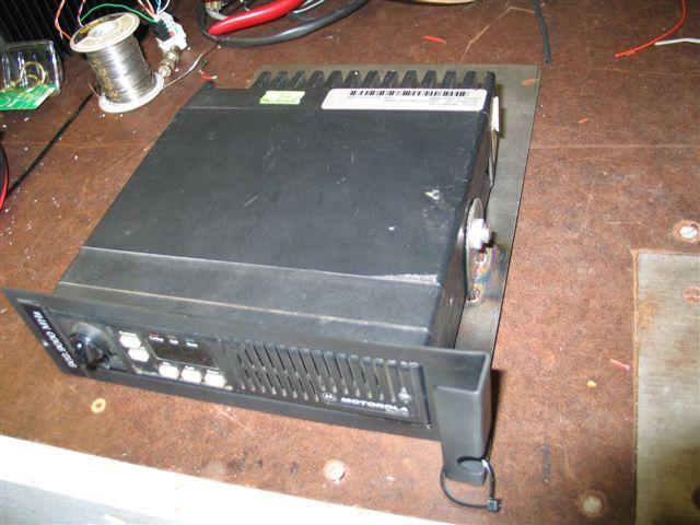
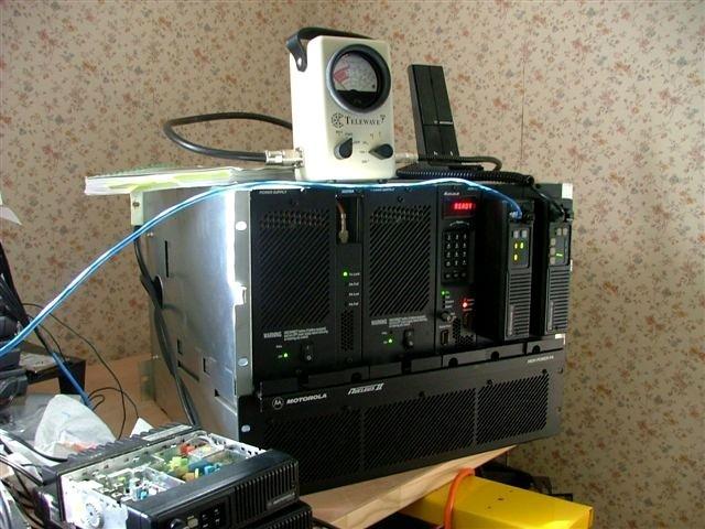
The Nucleus transmitter used for this article finally went into service on 27-Feb-06 as a replacement repeater. The original 12w MaxTrac 900 MHz transmitter is configured as a standby transmitter that is switched into service if the Nucleus should lose power. The photo below shows the Nucleus II transmitter in its enclosure, with the duplexer on top, the repeater controller directly underneath, and the MaxTrac transmitter and receiver on the bottom. The transmitter is putting out 130 watts, mainly due to power restrictions imposed by the duplexer.
Mark KD6WLY installed a receiver and repeater controller into his Nucleus cabinet and made it a fully self-contained repeater. He supplied the next two photos. The first shows how he mounted the MaxTrac into one of the blank panels.
This is what the complete repeater looks like.
Tom KN5S installed a MaxTrac radio as a modulator as well as a MaxTrac 900 MHz radio as a receiver. He supplied the next three photos. He made a cutout in the blank front plates through which he passes the control head wires, and drilled two holes for the original control head mounting screws, as shown here:
He sandwiches the blank plate between the control head and radio chassis, as shown here. The top and bottom plastic covers no longer fit on the radio. Contact Tom directly for cutting measurements.
This method of mounting does mean that the radio sticks out about an inch more than the Nucleus, so if you have your equipment in a cabinet, you will probably have some interference with the front door. Here's a photo of his repeater setup on the bench:
A Partial Schematic - Finally:
Someone had mentioned that the Quantar exciter was similar to the Nucleus version. Eventually I acquired a component layout and schematic for a Quantar 900 MHz exciter board. This at least confirmed the connection points and also showed that the exciter has both VCO MOD and REF MOD audio inputs. However, most of the components for the REF MOD circuitry were missing on the Nucleus exciter. Since it only has to deal with paging signals, there was no need for low-frequency modulation. This explains why the unit handled DPL modulation so poorly. Synthesized exciters are very good at adjusting for small changes in the carrier frequency, which is exactly what DPL does when used to modulate the VCO. To get around this problem, modulating audio is also fed to the reference oscillator to modulate it at low frequencies. This is done on the MaxTrac and Quantar, but without the components on the Nucleus exciter, it just can't happen, so the frequency deviation is counteracted. If I had the proper equipment and parts, I could populate the Nucleus exciter's REF MOD circuit and connect it to the REF MOD signal in the MaxTrac. I'm sure that with some fiddling I could get the DPL signal to look just as clean as it does on a MaxTrac. But for now, I'll just stick with regular PL.
Bonus Section - Neat 'N' Nifty Nucleus Notes:
These are little tidbits of information gleaned over the few months of experimenting. Some of this information is hidden in the User's Guide.
The default front panel password is "6000". This can be changed once you gain access to the system. It can also be completely defeated. I found it handy to disable the password while working on the station on the bench.
The NIU has an internal oscillator that is used as a frequency reference for the SCM. This 5 MHz signal can be measured at the front panel BNC jack on the standard controller or one of the backplane BNC jacks. This signal varies wildly while the station is initializing itself, then it locks on to the NIU's oscillator and can be tracked with a frequency counter. Three minutes after the station becomes ready for use, this reference signal is within 0.1 Hz of its final value. After eight minutes, it has reached its final value and doesn't vary more than one part in one billion (0.005 Hz). The transmitter's output is approximately 200 times the reference frequency, so an error of 0.1 Hz here means an error of only 20 Hz at the antenna.
The two power supplies draw 1200 watts when the station is putting out 300 watts of RF.
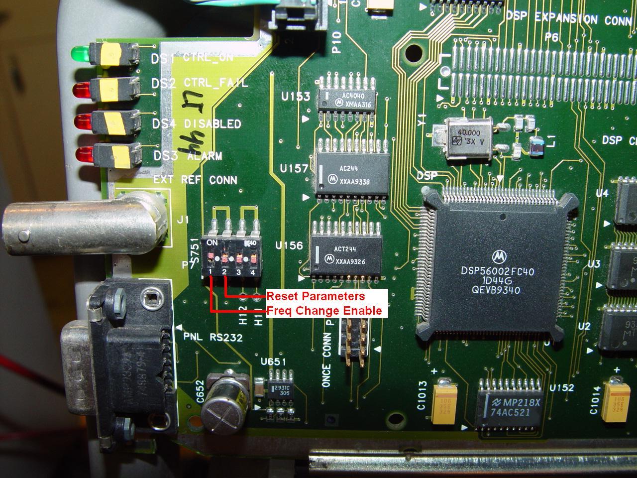
The standard controller has a four-section DIP-switch located near the lower front edge of the circuit board. The user's guide only documents one section. I called Motorola and got the real story.
This switch is only read when the station is powered up or restarting after a RESET command has been given. Once the display starts scrolling messages, you can return the switches to their OFF position.Section #1 (the one closest to the front panel) is raised (turned ON) to allow changes in frequency programming. If this switch is found on, the display will show "FREQ PROG ENABLED" when it powers up. I decided to leave mine turned on all the time so I can change frequencies all the time.
Section #2 is raised (turned ON) to completely reset the station's data, including the front panel password, all frequencies, power settings, options, etc. The display will show "FACTORY DATABASE PRESET" when it powers up. Once it does this, turn the switch OFF so all your new settings will remain in the controller.
Sections 3 and 4 are not connected and do absolutely nothing.
To reset the station to factory defaults, turn off the power, remove the control panel, flip up switch sections 1 and 2, and turn the power back on. When the station finishes initializing, turn off the power, turn off section 2, replace the control panel, and turn the power back on. You'll need to use the default front panel password of "6000" to gain entry. It can be defeated by pressing STN, then down-arrow three times to get to FRONT PANEL PASSWORD, then ENTER, then TOG to set it to DISABLED, then ENTER, then EXIT.
You'll need to set at least one transmit frequency via the TX menu. You'll need to set the options - circulator, wattmeter, and frequency reference type - via the OPT1 menu. The DISABLED LED will likely be illuminated until you've done at least this much. It will go off eventually or after you reset or power-cycle the station. Similarly, the ALARM LED will be on initially but it will go off if everything is normal. You can see what conditions are causing the alarm by pressing the ALRM button and cycling through the stored alarms using the down-arrow button. Usually resetting or cycling power to the station will cause a RESET alarm, which will disappear after several minutes. The wattmeter and power amplifier should be calibrated via the ALGN menu. Make sure the transmitter is connected to a good dummy load for this step.
The front panel "console" connector on the NIU board talks to an ASCII terminal or emulator program. I made up the cable using a pair of female DE-9 connectors and a few feet of the same Belden 8723 cable I used previously with the wiring as per the table below. In use, it doesn't matter which end goes to the Nucleus, as the cable is symmetrical.
| DE-9 Pin | DE-9 Pin | Function |
|---|---|---|
| 1 | 4 | Handshaking |
| 2 | 3 | Data |
| 3 | 2 | Data |
| 4 | 1 | Handshaking |
| 5 | 5 | Ground * |
* If you use shielded cable then use the shield(s) to connect the two pin 5s. If you use the Belden 8723 then use one shielded pair for pins 1 and 2, and the other pair for 3 and 4. If you place 2 and 3 on the same pair the crosstalk will limit your distance.
The other pins are not needed. I usually solder pins 7 and 8 together on all DE-9 connectors (force of habit from the old days). The protocol is 19,200 baud, 8 data bits, no parity, 1 stop bit (8, N, 1). I used HyperTerm and Win95 on an old Hitachi laptop and it worked great.
When connected, hit the <ENTER> or <CR> key. You should be prompted with:
[ 0]NUCNIU> Enter Password: _
The default password is "complex" entered in lower case and
without the quotes. You can type:
help *
to get a list of the available commands. You can type:
help command_name
for a short usage message on any command in the first list. Use the command:
logout
to leave the system, or you can just pull the serial cable off the NIU's connector.
The NIU has a ROM version of XILINX, a Unix-like operating system. Commands can be shortened to the least number of unique characters for that command. The User's Guide describes all of the available commands.
You can determine the transmitter frequency range by entering the password into the control panel (if necessary) and pressing the STN (1) button. The first parameter that comes up is "TX FREQ RANGE: xxx-yyy MHz". Note that this is read-only and cannot be changed on a 900 MHz paging transmitter, but you can bypass the frequency range limit restriction on (at least) VHF stations with the advanced controller. After pressing STN, press the ALGN (down-arrow) button twice; TX RANGE CHECKING ENABLED should be seen. Press ENT, then TOG to disable the option, then ENT to save it. You can now enter frequencies that are outside the normal limits for the station, as long as the VCO remains locked. Of course, performance will not be guaranteed, so if it doesn't work, or runs erratically, don't complain to me.
Miscellaneous Information:
Mark KD6WLY adds this trick regarding frequency selection:
You can display the transmitter frequency range by pressing the STN button. The first
message that comes up is "TX FREQ RANGE: ____ MHz". Note that this is a read-only field
and it cannot be changed via the menu, but you can bypass the frequency range limit
restriction. From the top menu, press STN, press the ALGN button twice; TX RANGE CHECKING
ENABLED should appear. Press ENT, then TOG to disable the option, then ENT to save it.
Then EXIT. You can now enter Ham frequencies that are outside the normal limits for the
station.
Unfortunately, I can't find any reference to a "TX RANGE CHECKING ENABLED" field in any of my Nucleus manuals. It may only be present if your station has a specific firmware version. Some transmitters would accept frequencies as low as 927 MHz; others would not go below 929 MHz.
Reference Material:
Test Equipment Used:
Acknowledgements:
Thanks to Dave N1OFJ for his Nucleus expertise and for proofreading this article.
Mark KD6WLY provided the initial modulation connections. He installed an external controller and a MaxTrac as a receiver in his Nucleus and turned the whole box into a repeater.
Kurt N1PFC gave me the secret of how to reset the Nucleus back to factory defaults, which eliminates figuring out a prior owner's password. He also made some useful suggestions while proofreading the article.
Tom KN5S provided photos of his method of mounting the MaxTrac radios in his Nucleus chassis.
The author, Robert Meister WA1MIK, is no longer with us (a silent key) as of June 2021.
The current page maintainer can be contacted by way of the "Currently Maintained by" link above.
Tom KN5S can be contacted at swrwax [ at ] earthlink [ dot ] net.
Back to the top of the page
Up one level
Back to Home
Article text, artistic layout, and hand-coded HTML © Copyright 2005 By
Robert W. Meister WA1MIK.
Date of last update by Mike Morris WA6ILQ.
This article first posted Sept 2005.
This web page, this web site, the information presented in and on its pages and in these modifications and conversions is © Copyrighted 1995 and (date of last update) by Kevin Custer W3KKC and multiple originating authors. All Rights Reserved, including that of paper and web publication elsewhere.