Up two levels (Moto index)
Back to Home
By Mike Morris WA6ILQ
|
Up one level (RSS page) Up two levels (Moto index) Back to Home |
An overview of the Motorola Radio Interface Box (RIB)
By Mike Morris WA6ILQ |
|
Note that saying "the RIB box" is redundant - you are saying "the Radio Interface Box box". So stop that!
The "real" Moto RIB, the RLN4008 (any version), is a black box that connects to the computer's serial port (either a DE-9 or a DB-25) with a custom cable (described below), and a second cable (the "radio programming cable") connects the RIB to the radio. This second cable is different depending upon the radios connector ‑ some use a RJ45 to the microphone jack (example: MaxTrac, GM-300, etc), some use a D-shaped connector on the radio chassis (example: Spectra), others use a unique connector (example: handhelds like the Saber, MT1000 or XTS series).
Click here for a photo fo a real Motorola RIB. It uses a DA-15 connection (with a weird pinout) on the computer end, and a DB-25 on the radio end. Many clones replace the DA-15 with a DE-9 and use a straight through cable (i.e. extension cord) to the computer. More on this later.
In other words, the connection is like this:
+------------------------+      +--------------+      +-------+    +-------------+
!   Desktop or           !      ! Radio        !      !       !    !             !
!   Laptop      COM port -------- Interface    -------- Radio ------ Dummy load  !
!   Computer             !      ! Box (with    !      !       !    !             !
!                        !      ! or without   !      !       !    !   See the   !
+------------------------+      ! the internal !      !       !    !  text below !
                       !        ! 9v battery)  !      !       !    !             !
                       !        +--------------+      +-------+    +-------------+
                       !               !                   !
                       !               !                   !
                       !        wall transformer     DC power supply
                       !          power supply        (recommended)
                       !          (see text)         or a fully charged
AC Mains outlet --+    !               !             radio battery if
                  !    !               !              you feel lucky
+-----------------!-+  !               !                   !
!                   !  !               !                   !
! Uninterruptible   !  !               !                   !
!  Power Supply     ---+               !                   !
!     (UPS)         !                  !                   !
!                   -------------------+                   !
! See the text      !                                      !
!     below         -------------------------------------- +
!                   !
+-------------------+
|
Why the Dummy load? Just in case. It takes but a few seconds to connect the termaline, and there are some RSS steps that key the transmitter. Like a surgeon that does certain procedures the same way, every time, if you ALWAYS attach a dummy load to a radio under test before you power it up then you won't ever have to say "Oops".
Why the UPS? I use both a desktop computer and an older laptop for programming radios. The desktop runs on AC power (naturally) and the battery in my programming laptop was, for a long tine, pure unobtanium so I ran it off the AC adapter. I do not need another customer radio bricked by a AC mains power failure during an upload. Besides, the UPS was free (except for the cost of the new batteries). You would be amazed at how many computer-grade UPS units are tossed into the trash because the owners do not care to learn how to swap a gell-cell (or two). Make friends with someone in the Information Technology world - someone who works on LANs, WANs, or does desktop support for a living. You can also buy UPSs used on eBay, just make sure you get a warranty and that the seller will ship it without the old dead batteries. Then buy the new batteries locally (a Sealed Lead Acid Battery, or SLAB, the generic term for a Gell Cell - due to the weight, is very expensive to ship). If you can't find them anywhere else, look for a burgular alarm supply company like ADI. Recently I've also seen them in lawn mower shops - electric mowers use 12, 24 or 36 volts from either 7AH or 18AH 12 volt batteries... the 24 volt models use two in series, the 36 volt models use three.
Note that some UPS models have a momentary outage as they switch from pass-through to inverter modes, and count on the capacitors in the loads (the computers plugged into them) to carry over the instantaneous dropout (APC models are famous for this - just plug an incandescent lamp into one, and pull the wall plug on the UPS... you will see it blink off and then come back on as the AC drops out and the inverter kicks in). You really want a UPS that has zero dropout.
Another solution if you don't have a UPS: power the entire programming session from batteries - the laptop can run on it's own battery, the RIB and the radio can run off a 12v gell-cell. Many laptops had 12vDC adapters available for them that allowed use in a vehicle (i.e. pluged into the cigarette lighter). One of those could be used to power the unit off of the same battery that powers the radio. If your laptop uses a battery that is no longer available then you can usually determine what the voltage should be and come up with an alternate source, then crack open the battery case, gut it of the dead cells and solder a piece of zip cord to the contacts. Then connect the zip cord to your alternate voltage source. A few years ago I saw an old 386 laptop connected to a series connection of two gell cells - a 12v 7.5AH and a 6v 7.5AH. The laptop zip cord and the battery set each had a set of Anderson power poles, one black (negative) and one purple (positive 18v). The purple one was twisted 90 degrees so that a radio could not be plugged into it (i.e. it was idiot proof).
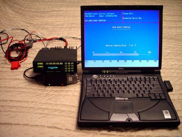
Below is a photo of a programming sesion. The radio power supply, RIB wall
wart and laptop power supply are out of the photo. The RIB is propping the
Spectra radio up at a decent angle for the camera. The RIB has two LEDs, a
green one for power on, and a red one for serial activity (data flow). As
visible in the photo it was taken during a code plug download.
A RIB shopping list:
The real RLN4008n RIB is very forgiving as to the wall-wart power pack, and almost any DC adapter with good filtering from 8 to 13 volts DC output and a current capacity of 50 ma or more will work fine. If you need to change the plug on a random DC adapter the proper replacement that mates with the Moto RIB is a 5mm (outside diameter) by 2.5mm (inside diameter) coaxial connector. Radio Shack calls it a "Size L" power connector and sells a package of two under the part number 274-1568.
Note that the RLN4008, RLN4008A and RLN4008B models of the RIB are known to use through-hole components and are bench repairable. The RLN4008D and later are known to use surface mount... (anybody have a "C" model and can look inside?) I bought a used B version since I needed a RIB at that time, the price was right and I knew I could repair it if I blew it up.
The older RIB service manual, part number 6880309C92 has a RIB theory technical writeup plus diagrams for several RIB‑to‑Radio cables. Once you study the RIB schematic, plus the radio cables, you will find that in some cases you can adapt cables and make do with alternate connections... as one example, you can convert a speaker-microphone plug for some handhelds into a programming plug (the HT1000 / MT2000 series and the MT1000 series can be prograammed this way). And sometimes you can make an alternate connection to the programming port on a radio - for example, the stock programming cable for the Syntor X9000 mobile was designed as a male / female "sandwich" block that was inserted between the radio chassis and the control cable. They are rare ‑ I've seen exactly two available in three years of eBay. Since the programming connection on the X9000 is six conductors, the standard mod is to add a DE-9F or 6-conductor RJ11 pigtail into the X9000 control cable connector, then to manufacture your own matching RIB-to-DE-9M or RIB-to-RJ cable.
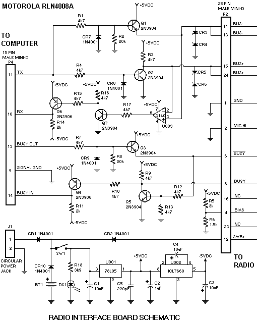
Part number 6880309H26 is the current RIB manual as of this writing. Until it arrives, click here for the schematic of the real Motorola RIB. On the schematic P2 is a DB-25 male and is for the cable that talks to the radio. P4 is a DA-15 and is for the RIB-specific cable that goes between the serial port on the computer and the RIB and is wired as follows:
|
|
|||||||||||||||||||||||||||||
Some notes on building your own RIB:
| RIB to Dual Computer cable | ||
| RIB end DA-15F pin |
Computer end DB-25F pin |
Computer end DE-9F pin |
| 11 | 2 | 3 |
| 10 | 3 | 2 |
| 13 | 20 | 4 |
| 9 | 7 | 5 |
| 14 | 5 and 22 | 8 and 9 |
From an email received by repeater-builder...
The two-way community around here is a close-knit group and a bunch of us get together ever other month for lunch and to trade war stories. Some of us have had problems using the stock Moto RIB on different computers, usually laptops. It boiled down to be a lack of negative voltage swing on the Busy out and RX (data out) lines back to the computer. These changes fixed it:Not only do the above resistor changes result in the voltages more closely matching the RS232 standard, but they also slightly reduce the current drain of the RIB making the little 9 volt battery last a bit longer.
- R1 and R4 change to 9.1K
- R3, 6, 9, 10, 12, 15, 16, change to 10K
- R5 becomes 39K
- R11 becomes 1K
- R14 becomes 1.5K
- R17 becomes 20K (not 22K - use a 18K and a two 1Ks in series)
From another email:
I was recently trying to program a Spectra DeskTrac tabletop base station at our broadcast site and was getting RF interference into the RIB. I ended up having to uncable and remove the DeskTrac and drive down the road and program it there. My permanent fix was to add some RF bypassing inside the RIB. I added one 220pf cap (that value only becuase I had a bunch in the truck parts drawer) from each of the following pins of the 15-pin connector (the computer connector) to ground (pin 9): 10, 11, 13, and 14 (i.e. all the active signals). As long as I was inside the RIB, I added the same to the DB-25 connector (the radio connector) pins: 4, 6, 11/13, 12 and 15/24. Since I've made this mod I've not seen any more RF problems ‑ I've sucessfully reprogrammed the DeskTrac on site, and tested my mod further by reprogramming a MaxTrac at much worse (RF-wise) sites. Another value other than 220pf may work better but these were in vehicle stock and worked. Doing both connectors may have been overkill, but I had the extra capacitors and didn't have the time or the inclination to open the RIB twice.
The RIB internal circuitry does the following functions:
Do not let the 9v battery in the RIB get old enough to sag in voltage while programming. The battery option was intended strictly for field work, for example using a laptop to update an already-installed mobile radio, like a front mount radio in a fire truck or ambulance. If the battery voltage sags mid-upload you can easily brick a radio, so always keep a fresh battery on hand and swap it out if you have any concerns. Save the questionable batteries for your kid's MP3 player or the TV remote control ‑ if it dies there it's not going to leave an ambulance out of service. Better yet, make up a cable that plugs into the cigarette lighter connector and powers the RIB.
If you are building your own RIB, make sure it has an outboard power connector and an internal battery complete with a voltage test indicator ‑ all it takes is a pushbutton, a resistor, a zener diode and a LED.
If you are going to be storing the RIB in the bottom of a rarely used toolbox remove the battery. You don't need it leaking all over the RIB PC board... (this is the voice of experience speaking...)
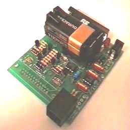
There used to be a very nice aftermarket RIB made by a gentleman named Sandy Ganz, but he evaporated some time in the 2008-2012 time frame. One nice feature of his product that no other clone RIB seems to have is an RJ-45 connector on his on his RIB that was wired to allow use of a standard ethernet cable to talk to a Maxtrac, Radius, GM300, GTX or any other radio that used that programming cable. A slide switch selected either the RJ-45 or the DB-25 (for all other radios). As I said, Sandy seem to be not around any more, so here is his RIB information as a multi-page PDF. The first page is the schematic, the second page is a circuit board layout, the last page is a handwritten parts list with Mouser part numbers. A photo of his board, partially assembled, is here (it's the only photo I have). If anyone knows what happened to Sandy, please let WA6ILQ know.
As shown above my own workbench programming setup has a surplus uninterruptible power supply (UPS) that I resurrected with new gell-cell batteries. It powers:
Motorola now sells a newer version of the RIB called a SmartRIB, SRIB or S-RIB (click for photo). The SmartRIB, the RLN1015, is backwards compatible with all the functions of the old RIB. It does however contains it's own microprocessor and a buffer memory for flashing the ASTRO and later series of radios. The firmware is loaded into the RIB and then the RIB MCU flashes it into the radio. Supposedly it is not possible to build a Smart RIB from scratch as it uses custom application specific IC's that are made by Moto Semi for internal use by Moto Comm and are totally unavailable to the public. The old RIB can be used to program every function of the latest radios except installing a flash firmware upgrade.
A WARNING ON THE SMARTRIB: the
center pin of the SmartRIB power plug is NEGATIVE, the exact
opposite of the RLN4008 series older RIBs. DO NOT
exchange the wall warts between the SmartRIB and a standard RIB
by accident. How a totally avoidable screwup like that
got past Motos design review process is beyond me. This
negative-tip situation is opposite from almost every other
wall wart used in Moto's products. Why couldn't they use
correct plarity? Or a different plug? This was totally stupid
as you can kill a serviceable SRIB if you use the wrong wall wart.
The negative voltage wall wart that came with my SRIB is now
painted with a neon green paint stripe - I store it and the SRIB
(also marked with a neon green paint stripe) in the same cardboard
box (also marked with a neon green paint stripe). As of this writing
SRIBs are very hard to come by, and they are outrageously expensive
when they do come up. Save your SRIB!
A good policy on ANY wall wart power pack is to label each one and
its associated equipment as they come into your shop with a
peel-and-stick label (Brother P-Touch or similar) and put a piece
of the thick clear shipping tape over the identifying label.
There are several versions of the SRIB, you want version "D" or
later. This version identifies the amount of internal flash in
the SRIB, and D is needed for flashing the 1 megabyte radios.
There are manufacturers that build so-called "RIBless" cables. They aren't really RIBless as these cables take advantage of a design quirk in the serial port (sometimes called the data port) built into some radios which allows the use of a very simple RIB circuit that will fit into the cable connector shell. These expensive cables are capable of programming a limited number of radios: model numbers include the GP300, GM300, GP350, MaxTrac, Radius Mobile, etc. and several others. They are attractive to those folks that have a fleet of all or mostly one kind of radio.
Then there are some "RIBless" cables that have a USB connector on the end instead of a DE-9 for the serial port. They essentially have BOTH a USB to serial adapter AND the RIBless circuitry in the connector shells. These are designed for RSS or CPS that runs under Win2k or XP. USB cables of any kind are totally USELESS on DOS-based RSS as DOS has no concept of USB, so if you get one you are limiting yourself to only those radios that have Windows-usable RSS or CPS software. Yes, Windows 95, 98 and ME had some USB support but it was very inconsistent - it would work with some programs and not others, and on some motherboards, and on some serial adapters, but not every program, adapter, or motherboard. And there are "real" and "clone" USB-to-serial chipsets, with the driver hassles that go along with them. All in all, if you can avoid the USB hassles and stick with computers that have real a serial port you will be MUCH better off.
Personally, I'd build (or buy) a real RIB and a dumb cable because if you have problems with a RIBless cable you will never know if it is the USB to serial converter, the quirky RIB circuit or the radio or.... ???? Every friend of mine that has bought a RIBless cable has sooner or later ended up getting a real RIB ‑ for one of two reasons: either he gets a better radio, for example graduating from a GM300 or MaxTrac (that can use a RIBless cable) to a Spectra (that can't), or he's damaged the expensive RIBless cable (try and get a schematic of it to do any troubleshooting, and some are nonrepairable because they are molded rubber or potted). Either way he's decided that a RIB and a repairable or duplicate-able home-made dumb cable is a more cost-effective arrangement in the long term. Also some of the clone RIBs have difficulty in knowing when to send and when to listen. The real Motorola RIB has additional circuitry that takes care of this task, along with circuits that handle interfaces with the more complex radios, such as Syntor, Astro, Spectra and MTS series.
Another reason to avoid the RIBless cables is the outright cost. You can buy a RIB for less, or build one for zero if you have a decent junk box, and build a cable for a radio for the cost of the materials. I built a RIB and my own home-brew cables for MSFs, MT1000, HT1000/MT2000, HT750/1250s, MaxTrac, Maratrac, Radiuses, GM300s, GTXs, R1225s, CDMs and several others.
Note that there are a number of radios that do not use a RIB... instead the RSS talks through the PC serial port directly to the radio (just mentally picture the RIB being built into the radio). The MTR2000, Nucleus, Quantar and Quantro are in this family. The SL300 handhelds use a microUSB cable!
Many Moto handheld radios program through the accessory connector. In most cases a replacement speaker-microphone cable can be adapted to function as a programming cable. For example on the HT600/MT1000 series you simply move three wires and replace the speaker-mic with a DB-25F connector. Details are on the "Genesis Series" page at this web site. The same trick holds true on the HT1000 and MT2000 (part of the Jedi series).
Almost all the mobile radios that use an RJ45 microphone
connector are programmed through the front panel mic jack,
and they all use the same two pins for programming (one for
bidirectional data and the other for ground). The easy way
to program that class of radio is to build a DB-25F to RJ45F
adapter that will plug onto the radio connector of the RIB,
and wire that adapter to allow using a regular ethernet
jumper cable between the radios microphone jack and the
adapter. And since the Maratrac has switched +12 on
pin 1 of the programming cable you can have a third
active wire in the cable connected to pin 12 of the
RIB. An extra toggle switch in series with pin 1 of
the radio and pin 12 of the RIB allows the Maratrac
to power the RIB, or to isolate any added circuitry that
connect to pin 1 in a MaxTrac, Radius or GM300 (see the
"Repeater Controller Interfacing" articles on the MaxTrac
page).
Later radios like a CDM or a CM series mobile need a
resistor added internally to the cable. The modified
cable is backward compatible with the older radios.
Note also that the RJ45 pin orientation for Motorola mobiles is backward from most other RJ45 uses. And the DeskTrac product numbers the pins backwards from the MaxTrac (but the function is the same). Most other wiring diagrams (i.e. network cables) disagree with the older Motorola mobile diagrams. That's why the MaxTrac page at this web site has photos.
Contact Information:
The author can be contacted at: his-callsign // at // repeater-builder // dot // com.
Back to the top of the page
Up one level (RSS page)
Up two levels (Moto index)
Back to Home
This web page is copyright by Mike Morris WA6ILQ 2003 and date of update.
Motorola® is a registered trademark of Motorola Inc. CPS, HT600, MICOR, Mostar, MT1000, R100, Radio Service Software, RSS, Radio Interface box, RIB, Saber, SmartRIB, Spectra, STX, Syntor, Syntor X, Syntor X9000, Systems Saber and other terms used in this article are trademarks, service marks or copyrighted by Motorola Inc. and are used in this writeup and on this web site in a descriptive or educational use only, and no misuse or infringement is intended.
This web page, this web site, the information presented in and on its pages and in these modifications and conversions is © Copyrighted 1995 and (date of last update) by Kevin Custer W3KKC and multiple originating authors. All Rights Reserved, including that of paper and web publication elsewhere.