Back to Home
Motorola SM50/SM120
Mobile Radios
By Robert Meister WA1MIK (SK)
Maintained by Mike Morris WA6ILQ
Mike has very little hands-on experience with this equipment so please ask on the repeater-builder mailing list!

|
Motorola Index Back to Home |
An Overview of the Motorola SM50/SM120 Mobile Radios By Robert Meister WA1MIK (SK) Maintained by Mike Morris WA6ILQ Mike has very little hands-on experience with this equipment so please ask on the repeater-builder mailing list! |
|
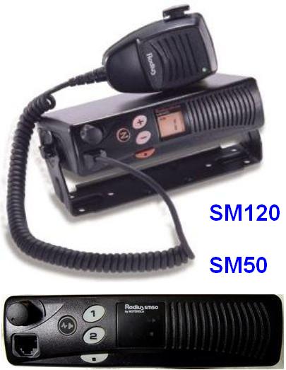
The SM-series (SM50 and SM120) mobile radios are part of the Radius product line. Naturally they have been discontinued and replaced by radios in the CM product line. They are basic low-end radios with models that cover 136-170 MHz and 450-490 MHz, in 10-15 watt and 25-45 watt versions, and narrow (2.5 kHz) and wide (5.0 kHz) bandwidth. The SM50 is two-channel; the SM120 is 16-channel. They are a lot smaller than their MaxTrac/Radius/GM300 cousins, measuring 1-3/4 inches high, 6-5/8 inches wide, and 4-1/4 inches deep. The two-pin power connector is attached to a pigtail piece of wire that sticks out the back of the radio. According to the spec sheet in the service manual, these radios draw about 300mA when idle, 1.5 amps at maximum receive volume, 7 amps VHF low power transmit, 8 amps UHF low power transmit, and 12.5 amps at 40 watts.
The radios are programmed with their own model-specific DOS software, just like all the other radios in the MaxTrac / Radius / GM300 product lines. Same equipment and environment restrictions apply. The latest version of RSS, HVN9007E, is R05.00.00, dated 01-Sep-98. The MDF file must be hex-edited for out-of-band programming; the SHIFT-NUM trick does not work on the SM50 program. Details can be found at the end of this article.
Note that even though these radios come in narrow-band and wide-band models, the programming software will only allow entry of TX and RX frequencies that are evenly divisible by 5.0 or 6.25 kHz. This means that frequencies such as 155.5000 MHz and 155.5050 MHz are valid but 155.5025 MHz is invalid and will be rejected. I found this out the hard way when programming an SM120 radio for someone.
The SM50 and SM120 probably would not work as well in repeater service as other Motorola products (such as the MaxTrac, Radius and Spectra models). They're just not heavy-duty radios. The heat sink of my SM50 gets hot after a 10 minute conversation (50% duty cycle) but not to the point where you'd burn yourself. It also cools off fairly quickly, but remember these radios are only designed for a 5/5/90 duty cycle.
The M1225 radio series seems to have similar model numbers and comes in several channel capacities. It looks very much like a CDM-series radio. This may have been the higher-end companion to the SM50/SM120 radios.
Do yourself a favor: add a dab of white paint or something like "White-Out" or "Liquid Paper" in the recessed dot of the volume control knob so you can tell where it's set. I don't know why Motorola paints such an indicator on some knobs but not others. Must be a budget thing.
Model Number Chart:
The model numbers follow the old Motorola 12-character "standard" scheme, however you can not tell which band-split the radio covers without opening it up and trying to find the part number of the main board (I could not find such a number on any exposed surface of my radio).
The first six characters of the model number are shown below.
| Mount Type | Power | Band | Series |
|---|---|---|---|
| M always | 3: 10-25w | 3: VHF-HI | DGC always |
| 4: 25-40w | 4: UHF |
The second six characters are shown below.
| Ch. Spacing (kHz) | # of Channels | Split (MHz) | Version | Options |
|---|---|---|---|---|
| 00: 12.5 | A: 2 (SM50) | 1: 136-156 | A always | A always |
| 20: 20/25/30 (VHF) | C: 16 (SM120) | 2: 150-170 | ||
| 20: 20/25 (UHF) | 2: 450-470 | |||
| 4: 470-490 |
For example, a 40-watt, UHF, 12.5 kHz spaced, two-channel, 450-470 MHz SM50 radio would have a model number of M44DGC00A2AA.
Common Features (and differences from MaxTrac/Radius/GM300):
The radios can be programmed for high or low power on a mode-by-mode basis. Low power is typically the low end of the power range. Local/Distance can also be programmed on a mode-by-mode basis. The local setting improves intermod rejection by reducing the gain of the receiver's front end. The front panel Option button overrides individual mode settings.
Mode numbers (on 16-channel radios) can be programmed to display 01 thru 99.
Quik-Call II, as well as PL and DPL, are the only available signaling systems. There are no MDC capabilities in these radios.
The 12.5 kHz spaced radios are normally configured for 2.5 kHz total transmitter deviation, but this can be changed (through re-alignment) to 5.0 kHz. The PL level can be set to discrete levels (500 or 750 Hz with the deviation set for 5 kHz).
Even though the 12.5 kHz spaced radio expects narrow-band (2.5 kHz) receive audio, the radio did extremely well when receiving audio with deviations as high at 6 kHz. I measured the receiver audio distortion at several frequencies and found it to be below 5% even with 7 kHz incoming deviation. As far as I can tell, the 12.5 kHz spaced radios ARE type-accepted for narrow-band operation and the service manual specifies narrow filters for both the high (45.1 MHz) and low (455 kHz) IF circuits.
The squelch setting is done through RSS; no squelch pot is present on the board. In fact, there are no tools required, or mechanical adjustments possible, for any alignment procedure. It's all done through the RSS Service menu, like most other Motorola radios that are programmed via a DOS program. My radio would only open the squelch with the alignment value set at 00. Anything higher resulted in a closed squelch. The higher it is, the less sensitive the radio will seem to be. Here are the various squelch opening sensitivities by value.
| Val | dBm | uV |
|---|---|---|
| 1 | -127.0 | 0.100 |
| 2 | -125.0 | 0.126 |
| 3 | -123.5 | 0.149 |
| 4 | -122.5 | 0.168 |
| 5 | -121.5 | 0.188 |
| 6 | -121.0 | 0.199 |
| 7 | -120.0 | 0.224 |
| 8 | -119.0 | 0.251 |
| 9 | -118.5 | 0.266 |
| 10 | -118.0 | 0.282 |
| 11 | -117.0 | 0.316 |
| 12 | -116.0 | 0.354 |
| 13 | -115.0 | 0.398 |
| 14 | -113.0 | 0.501 |
| 15 | -111.5 | 0.595 |
There's a "maximum volume" setting in RSS that affects how loud you can run the receive audio. At full level, it is REALLY loud. I had to turn mine down a bit just so I could run the volume control past 1/2 way.
Both sides of the loudspeaker are driven (like in the GM300, unlike the MaxTrac). You can actually recover usable audio from either speaker lead to ground.
My radio had no problem accepting and operating with 444 MHz frequencies once I hex-edited the MDF file to expand the UHF frequency range (from 450-470 MHz) to 440-480 MHz; see the details below. It also seemed quite happy to control its transmit deviation and output power below 450 MHz. At 444.450 MHz I measured 20dB quieting at -118dBm (0.282uV); at 461.000 MHz I measured 20dB quieting at -119dBm (0.251uV).
A reader inquired whether the SM50 would work down near 440 MHz (many areas have repeater outputs from 440-445 MHz), so I programmed my radio with 440.000 simplex and 480.000 simplex and tested it out: 40 watts on 440, 38 watts on 480. Sensitivity was -117dBm at these two frequencies, just a bit worse than in the band the radio was designed for.
Differences Between the SM50 and SM120:
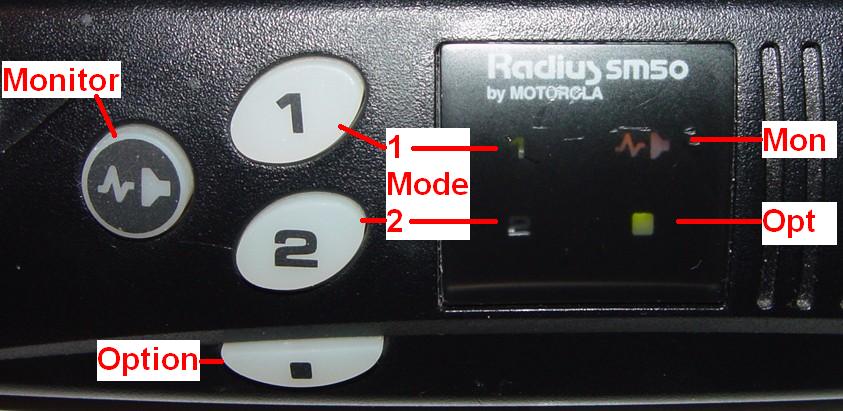
The SM50 models are all two-channel (or mode) radios, while the SM120 models are all 16-channel radios. The front panel buttons on the SM50 are marked "1" and "2" and mode LEDs illuminate to tell you which channel is selected: solid green for receive/idle, flashing red for receive/active, and solid red for transmit. The photo below show the SM50 with all indicators identified.
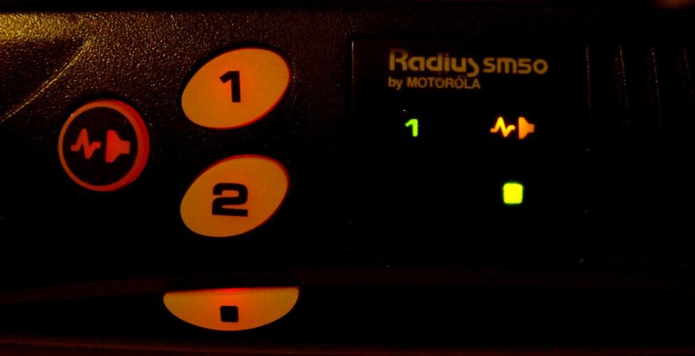
Since everything is back-lit, here's what it looks like in a dark environment with the monitor and option buttons activated. The illuminated silicone buttons can best be described as having a dark "pink grapefruit juice" color.
The buttons on the SM120 are marked "+" (up) and "-" (down) and a two-digit back-lit LCD display tells you the current channel number (like a MaxTrac/Radius/GM300). The display has additional indicator icons for scan, monitor, and other options.
The SM120 models have scanning capabilities; the SM50 models do not.
The SM50 has a dedicated "Monitor" button that will place the radio in carrier squelch mode, or open the squelch if held for a few seconds. On the SM120, the button in this position turns scanning on or off, and you would need to program the Option button for the monitor function if you wanted it.
Both radios have a programmable Option button. The table below describes the available functions.
| Function | SM50 | SM120 |
|---|---|---|
| Repeat/Talk-around | Y | Y |
| Local/Distant | Y | Y |
| Selectable H/L | Y | Y |
| Monitor/Volume | N | Y |
| No Function | Y | Y |
Microphone and Microphone Connector:
The standard mike for the SM series is the HMN3174B "compact" microphone, however Maxtrac, Radius LRA, GTX, M1225 and GM300 mics work just fine. It's a serviceable black plastic unit (in other words, it has screws in the back and it can be taken apart and fixed) with a red/green LED in the upper right corner (green for receive mode, red for transmit mode) and an RJ45 plug at the end of the coil cord. The LED illumination is controlled directly by the position of the PTT switch in the microphone; it is NOT a "receiver unsquelched" indicator.
The SM50 / SM120 radios use the same microphones and programming cables as for MaxTrac / Radius / GM300 radios. The MIC jack pins are numbered 1-8 from right to left (backwards from RJ45 ethernet numbering) when looking into the front of the radio with the RJ45 tab down. This matches the other radios listed above.
| Pin | Function | Notes |
|---|---|---|
| 1 | +8V | NOT current-limited |
| 2 | Clone | Used for cloning radios |
| 3 | Hook | Ground for coded squelch |
| 4 | Ground | |
| 5 | Mic Audio | Has +8VDC bias present |
| 6 | PTT | Ground to activate |
| 7 | SCI | Bidirectional programming line |
| 8 | RX Audio | Fixed level, muted, de-emphasized |
Accessories and Cosmetic Parts
The official base microphone is the RMN5068A, but like the mobile microphone a large number of base mics will work. One is the HMN3000.
The mobile mounting bracket is the HLN9154A or RLN6469A.
A replacement Volume Knob is 3604414J02 or 1885724L01.
The Accessory Connector Cover or Gasket is part number 3202607Y01.
The official power cable is the HKN4137.
Accessory Connector:
These radios use the standard MaxTrac/Radius/GM300 16-pin accessory connector. There's a very nice image of one, complete with pin configuration tables, in the GM300 article elsewhere on this site; you should go find it and read it at some time. I can't force you to read it, but don't come crying to me when you wire it up wrong. The internal loudspeaker is always enabled, so you don't need an accessory plug installed to use the radio. The audio power amplifier provides 7.5 watts of power. It will drive an external speaker very well. The internal speaker is rather small (same as in a MaxTrac/Radius/GM300/GTX radio) and it will distort if the volume is turned up too loud. Any 8 ohm external speaker will work, just connect it to pins 1 and 16 of the accessory jack.
There are three preset package configurations: General, Remote, and Phone Patch, but you can customize any of the programmable pins through RSS. The following information was taken from the RSS manual.
| General I/O Package Default Configuration | ||||
|---|---|---|---|---|
| Pin | Function | Direction | Debounce | Active |
| 4 | NULL | Output | No | Low |
| 8 | NULL | Output | No | Low |
| 9 | NULL | Input | No | Low |
| 12 | NULL | Input | No | Low |
| 14 | NULL | Input | No | Low |
The Remote Package Default Configuration is the same as the above table except pin 14 function is "Mic Off Hook" and pin 14 has Debounce=Yes.
The Phone Patch Package Default Configuration is the same as the above table except pin 8 function is "PL/DPL & CSQ Detect" and pin 14 has Direction=Output.
| Input Functions | |
|---|---|
| Function | Description |
| NULL | Pin has no function |
| Mic Off Hook | Indicates to radio when a remote microphone is off hook |
| Auto PTT | Strips PTT ID and system busy alert tone |
| RX Audio Mute | Mutes Rx Audio |
| Emergency Switch | Activates emergency transmit condition |
| Output Functions | |
|---|---|
| Function | Description |
| NULL | Pin has no function |
| PL/DPL & CSQ Detect | Pin is active when TPL/DPL and carrier are detected |
| CSQ Detect | Pin is active when a carrier is detected by the radio |
| External Alarm | Driver pin for external relay when an Alert is received |
| Possible Pin Assignments | |
|---|---|
| Pin | Function |
| 4 (Output) | NULL PL/DPL & CSQ Detect CSQ Detect |
| 9 (Input) | NULL Mic Off Hook Auto PTT RX Audio Mute |
| 8, 12, 14 (In / Out) | Any of the above functions |
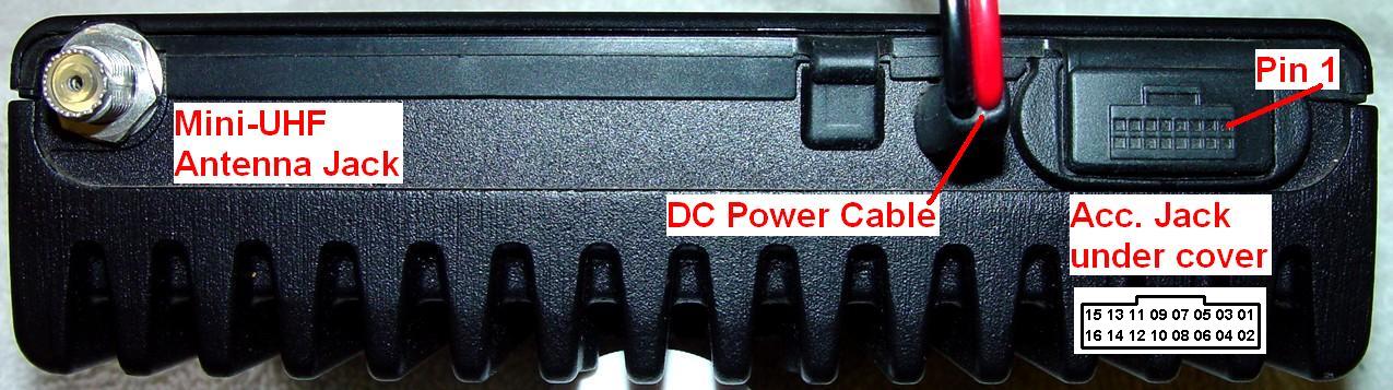
Looking at the schematic of the radio, I've determined the functionality of each pin on the accessory jack, summarized in the table below. When viewed from the rear of the radio, the top right pin is #1, as indicated on the photo below. A protective rubber plug covers the accessory jack when not in use. In fact, the entire radio is rather well gasketed and weather-resistant.
| Pin | Direction | Function or Signal Name |
|---|---|---|
| 1 | Out | External Speaker (-) [1] |
| 2 | In | External Mic Audio |
| 3 | In | External Mic PTT |
| 4 | Out | External Alarm / Programmable |
| 5 | In | Flat TX Audio |
| 6 | Spare | |
| 7 | In/Out | Ground |
| 8 | In/Out | Programmable I/O pin |
| 9 | In | Emergency Switch / Programmable [2] |
| 10 | In | Ignition Sense [3] |
| 11 | Out | RX Audio [4] |
| 12 | In/Out | Programmable I/O pin |
| 13 | Out | Switched A+ |
| 14 | In/Out | Programmable I/O pin |
| 15 | In | Internal Speaker (+) [5] |
| 16 | Out | External Speaker (+) [5] |
Like the Maxtrac, Radius LRA and GM300 series the antenna connector is a mini-UHF female and easy to break if you use an adapter and use stiff coax like LMR400, RG213 or RG214. Replacing the mini-UHF connector would not be easy. A mini-UHF male to "N" or BNC female pigtail cable for stress relief would be a good idea.
Appropriate Manuals:
SM Series Service Manual, covers both VHF and UHF radios, all power levels, SM50 and SM120, p/n 6880903Z45, cost about $24US in October 2009.
Radius SM Series Dealer's Radio Service Software Manual, p/n 6880903Z78, cost about $14US in October 2009. This manual is actually thicker than the service manual, mainly because it has info for a complete newcomer to Motorola programming software, including a tutorial on how to set up a computer, make directories, load software, etc. It easily could have been shortened by 50%. Also, the manual is incomplete in some key areas (service procedures), but since the product has been discontinued and they won't be printing revisions to the manual, it serves no purpose to let Motorola know about such deficiencies.
Opening It Up:
Not much to see under the radio (see photo below).
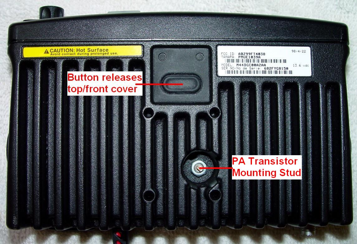
When I got the radio, I saw the rubber push-button under the chassis, but could not figure out how to get the cover off. It took a few seconds of reading the service manual to find the secret. Remove the volume control knob by pulling straight out, then push and hold the rubber button under the chassis to release the latch beneath it. Hold the chassis with one hand and slide the black plastic cover and front panel forward with the other hand. It comes right off. To reinstall it, line the cover up with the top of the chassis and push the cover backwards until the latch clicks, then replace the volume knob. If you need it a replacement knob is part number 3604414J02. It's the same knob as used on am M1225, and several other radios.
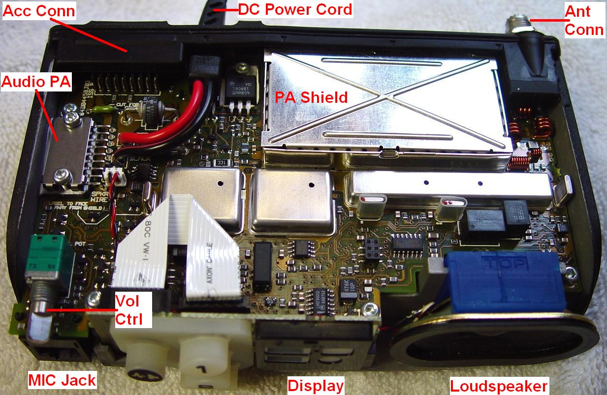
There's just one four-layer main board. The top has most of the stuff that would be on the RF board of a MaxTrac (receiver, transmitter, synthesizer) plus the power amplifier. The circuitry underneath is mostly stuff that would be on the Logic board of a MaxTrac (microprocessor and audio processing). A vertically-mounted display board attaches to a connector at the front of the main board. Here's what you can see inside.
Hex-Editing the MDF file:
The SM50.MDF file follows the layout and format of most of the other standard MDF files. There are three pairs of frequencies for each band that specifies the lower and upper limits for the TX, RX, and RSS screen. The location may vary according to the version of software, so it's best to search for the hex values (Intel byte order) rather than for me to tell you to change bytes at specific addresses. Remember to make a backup copy of the MDF file first; better to have it and not need it than to need it and not have it. Select the "Checksum (16-bit)" routine for the checksum and verify that it's the same after you've finished hex-editing the file.
Search for the four hex byte sequence 94,11,5C,12. You should find three occurrences of these values. The 94,11 corresponds to a decimal value of 4500 and the 5C,12 corresponds to a decimal value of 4700. These are equivalent to 450.0 and 470.0 MHz, which is the normal range for the radio and RSS. Change these three sequences of hex bytes to 30,11,C0,12, which corresponds to decimal values of 4400 and 4800 (440.0 and 480.0 MHz). By simultaneously increasing the value at one location and decreasing the value at another location, the MDF file's checksum remained the same. Save the results and you should be good to go.
There are similar bytes located around the ones above that handle the frequency ranges for VHF and other UHF ranges. They can be similarly changed. Just make sure you increase the upper limit by the same amount you decrease the lower limit, to keep the checksum correct. You can extend the range down to 140.9 and up to 179.1 by replacing the three occurrences of four hex byte sequence DC,05,A4,06 to 81,05,FF,06 but if you need to go further change them to DC,04,A4,07 and that will REALLY open it up.
SM120 Displays "FF":
After a programming session, the radio displays "FF" and it won't transmit at all. Cycling the power or rewriting the code plug doesn't fix a thing.
Apparently the "FF" indicates the radio did not exit programming mode properly. If you hold the '+' and '-' keys at the same time for three seconds, this seems to cause the radio to exit programming mode.
Acknowledgements and Credits:
Information for this article came from direct examination of a 40-watt UHF SM50 radio plus perusal of the above two manuals. I also changed my radio from 2.5 kHz to 5.0 kHz deviation and went through the entire board replacement procedures.
PL, DPL, SM50, SM120, Radius, MaxTrac, GM300, GTX, and a bunch of other terms are trademarks of Motorola, Inc.
Mike WA6ILQ asked several questions, which required additional research and several additions to the article, and also pointed out a couple of errors.
Contact Information:
The original author is a silent key as of June 2021. The current page maintainer can be contacted by way of the "Currently Maintained by" link above.
Back to the top of the page
Up one level (Motorola Index)
Back to Home
This page originally posted on Saturday 24-Oct-2009.
Photographs, article text, and hand-coded HTML © Copyright 2009 by Robert W. Meister WA1MIK.
This web page, this web site, the information presented in and on its pages and in these modifications and conversions is © Copyrighted 1995 and (date of last update) by Kevin Custer W3KKC and multiple originating authors. All Rights Reserved, including that of paper and web publication elsewhere.