Up two levels (Moto index)
Back to Home
900 MHz Mobile Radio
for Amateur Use
By Robert W. Meister WA1MIK
|
Up one level (Spectra index) Up two levels (Moto index) Back to Home |
Modifying the Spectra 900 MHz Mobile Radio for Amateur Use By Robert W. Meister WA1MIK |
|
Background:
The Spectra, like many other Motorola 900 MHz radios, is manufactured to transmit in the 896-902 MHz band, receive in the 935-941 MHz band, and transmit ("talk-around," "direct," or "simplex") in the 935-941 MHz band as well. The 25 MHz amateur repeater offsets call for inputs from 902-903 MHz and outputs from 927-928 MHz, in other words, the first and last MHz of that amateur band. The Spectra will easily transmit between 902 and 903 right out of the box, but it has some problems transmitting and receiving around 927. Luckily this frequency is well within the band-pass of the receiver, transmitter, and power amplifier; only the Voltage Controlled Oscillator (VCO) needs to be modified. Of course, you still have to make some changes to the programming software to allow out-of-range frequencies.
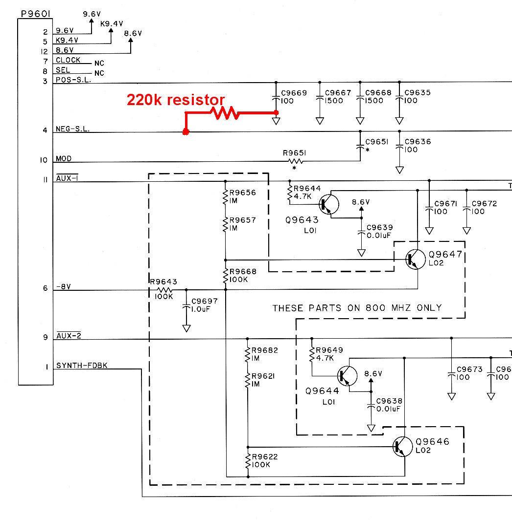
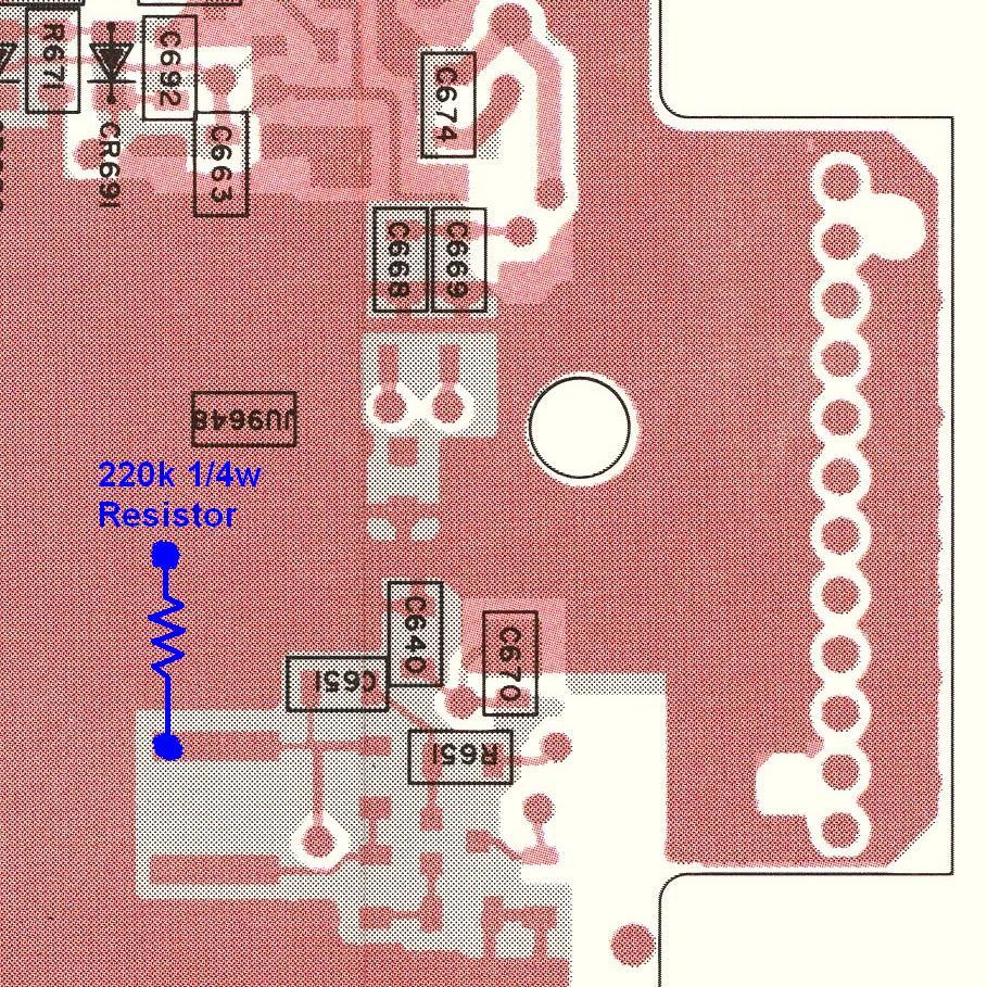
The only documentation I've seen on the web concerning the VCO mod is a scan of the VCO board layout with some hand-written notes on it that tries to tell you where to add a resistor to allow operation around 927 MHz. Unfortunately, the diagram is hard to read, and there is no schematic that tells you electrically what you're doing when you add that resistor.
With the schematic and board layout from the detailed service manual, plus some help from a couple of Spectra gurus, I've figured out exactly where this resistor goes: the negative steering line. It's marked on the schematic diagram below.
What You'll Need:
The modification consists of soldering one 220k 1/4 watt resistor to the negative steering line signal on the VCO board. Almost any value between 150k and 330k will work, but 220k is a standard 10% value. You'll need common electronic soldering tools and a T15 Torx driver.
NOTE: The Spectra electronic components are highly susceptible to damage from static electricity. Proper precautions should be followed when handling the radio with the covers removed. Always make contact with a major metal part of the radio chassis before diving further into the VCO board.
Step-By-Step Procedure:
IMPORTANT NOTE: Before you do ANY modifications, verify that the radio is operating properly in the stock frequency range: 896-902 and 935-941 MHz. Test talk-around as well. If you are getting FAIL 001 error messages on the display, even intermittent ones, fix the radio first. This is usually an indication of leaky electrolytic capacitors. See the Spectra Time-Bomb Capacitors article elsewhere in this section.
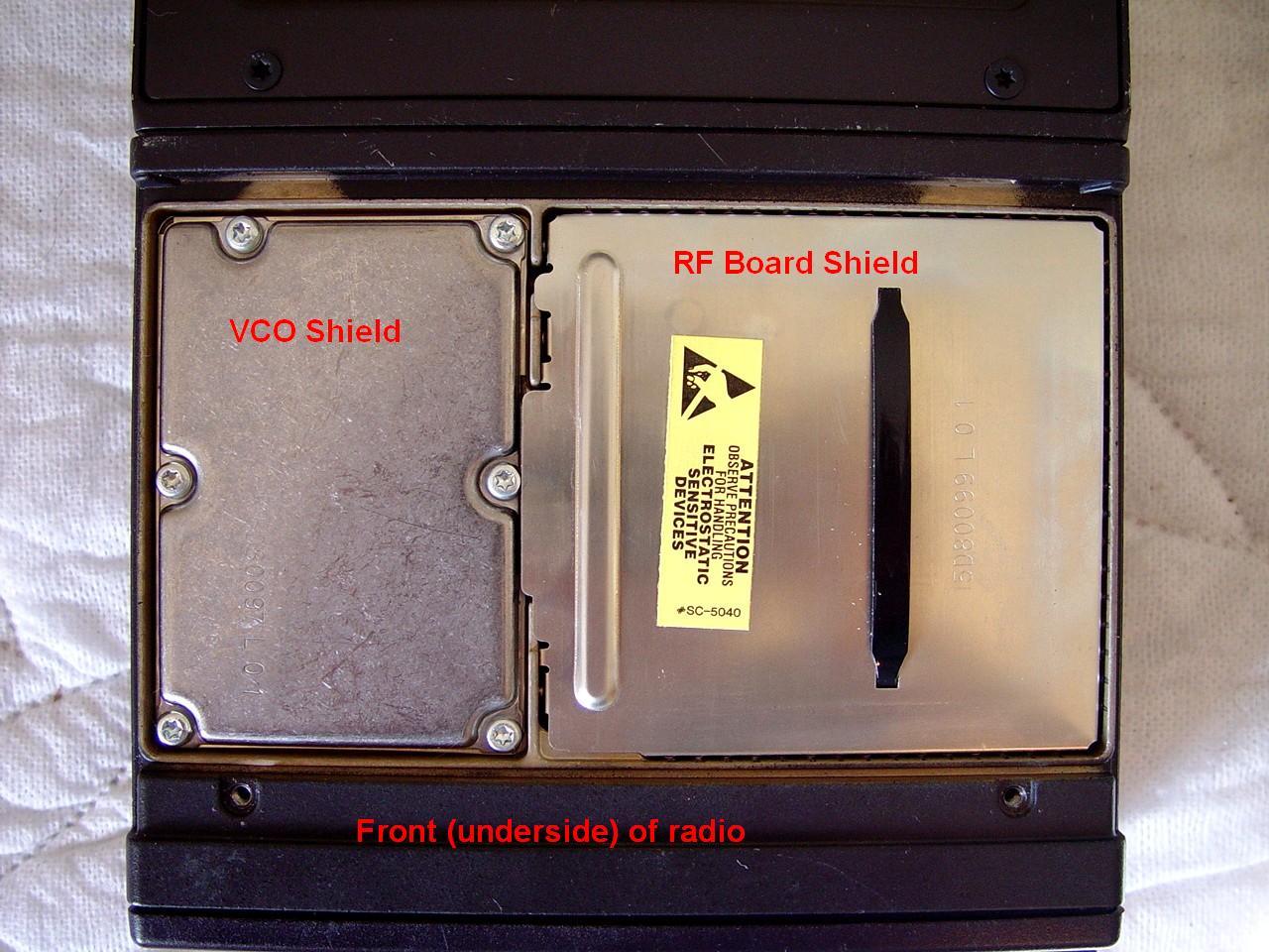
Remove everything connected to the radio chassis. Turn it over so the bottom is facing up and the front is towards you. Remove the two screws near the front of the radio that hold the bottom cover on.
Pry the two right corners of the RF board shield up slightly as you gently but firmly pull up on the black strap to remove the shield. It's a good, tight press-fit, so be persistent.
Remove the six T15 screws around the outside of the cover of the VCO board. Remove the VCO shield but leave the thin "gasket" around the outside edge of the board itself.
Locate the pair of strips near the middle of the board. See the photo below.
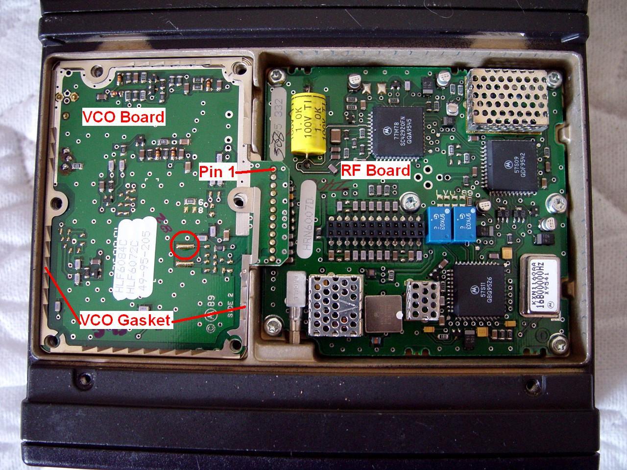
One end of the resistor will mount to the rear-most strip - the one in the circle in the photo above. The other end goes to any nearby ground hole. Cut the leads to about 3/8 inch long. Make sure the resistor will reach the circled pad. Stuff one end into a ground hole and solder it. Bend the resistor flat against the circuit board and solder the other end to the circled pad. It should look similar to the one in the photo below.
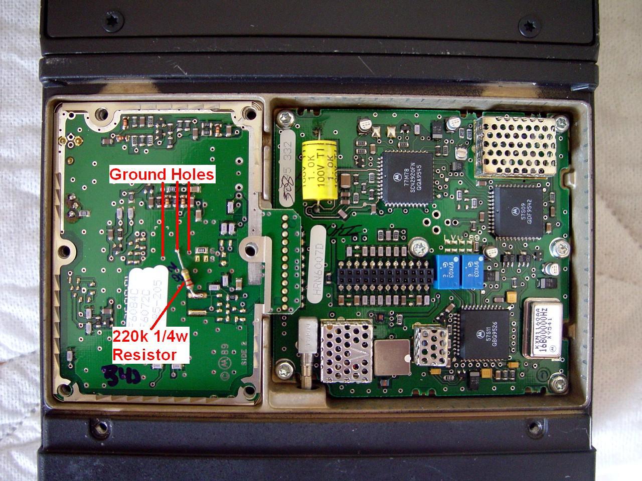
Here's where it gets installed according to the printed circuit board layout:
Push the resistor down flat against the circuit board. Reinstall the VCO shield, secure its screws to 6-8 inch-pounds (that's what the manual asks for - I just use my calibrated wrist), replace the RF board shield, and replace the radio's bottom cover. That's it; you're done with the modification.
If you haven't already hex-edited your Spectra programming software to allow ham frequencies, you'll need to do that. There are articles on the web that explain the procedure. I changed mine to allow 896-904 MHz and 926-941 MHz. Don't let the ranges overlap, and make sure the checksum is correct.
Alternative Methods:
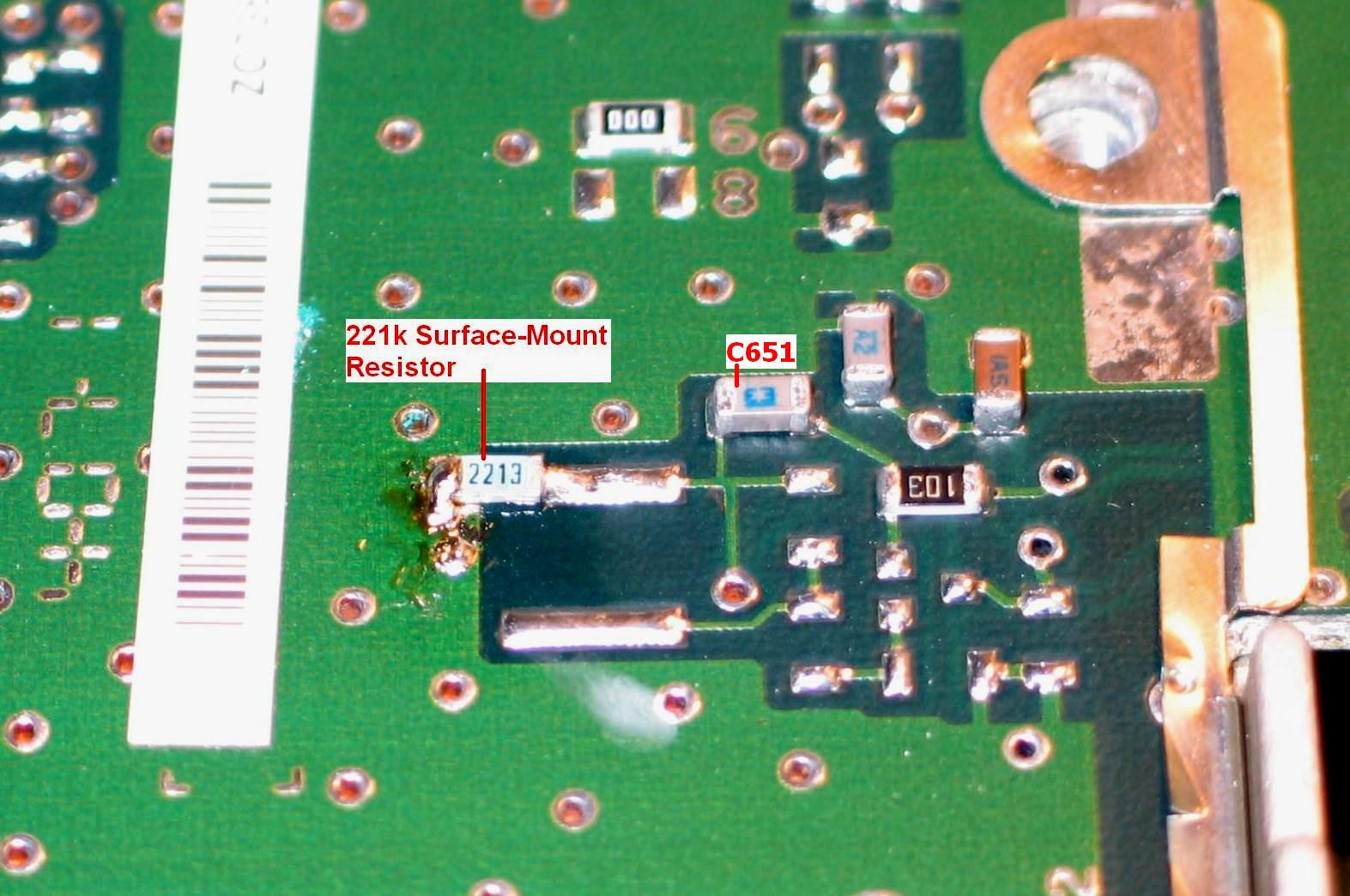
If you're comfortable working with small parts, can obtain them, and have the proper tools, you can install a surface-mount resistor (the value is not critical - the one in the photo is 221k) as shown below:
Or you can install a 220k 1/4 watt resistor from pin 4 of the VCO board connector to a nearby ground hole. You don't have to remove the VCO shield to do this. The problem with this location is that it may interfere with the RF board's shield, so placement is critical. You may have to put sleeving over the leads and bend the resistor down and underneath the VCO board, next to the pins that plug into the RF board. Pin 1 of the VCO board connector is towards the rear of the radio and is marked on one photo.
NOTE: This modification - a 220k resistor from pin 4 of the VCO to ground - seems to work for UHF (450-480 MHz) radios as well, allowing the VCO to operate down to 440 MHz.
UPDATE: Several people have suggested using a 100k resistor if you want to use your radio to work 12 MHz split repeaters on 900 MHz. There aren't any in my area so I didn't try it. The value does not seem to be too critical, and since a 1/4 watt resistor is easily handled, you could try 100k, 120k, 150k, 180k, 220k, 270k, 330k, 390k, 470k, or 1M, leaving the highest value which lets the radio work on the frequencies you want to operate. You might also have to replace the front-end filters (if you can find something that will fit and work) in the receiver to make it more sensitive around 920 MHz.
Increasing Transmit Deviation:
There's a little note I found on another web site that mentions adding a 0.003uF capacitor across C651 to increase deviation to over 5 kHz. Unfortunately it neglects to mention what board C651 is on. Well, if you check the VCO schematic you find C9651 which is 470pF on 900 MHz VCOs and something larger for lower bands. The board photo above labels it as C651 and it's very close to the spot where the resistor mod is connected. It has been marked in the photo above, near the surface-mount 220k resistor.
James WDØEKR reports that he got well over 5 kHz deviation with a 0.001uF capacitor, and the deviation setting in RSS was about half scale for 5 kHz. I'd suggest using a 470pF capacitor across C651 so the radio can't go too far above 5 kHz.
NOTE: The transmitter's modulation is fed into the VCO to the negative steering line on 800 MHz and 900 MHz radios. If the resistor you add to this point is too low in value, it could affect the transmit deviation. It won't change the deviation on VHF or UHF radios. If you have the equipment to check the deviation, do so before and after this modification and adjust it through the Service menu of RSS if necessary. The normal deviation level for 900 MHz radios is 2.5 kHz.
Technical Information:
Adding some seemingly random value resistor to the VCO pin 4 (negative steering line) may at first appear rather hocus-pocus. For some readers, this may be challenging enough. I decided to do some analysis of the VCO by playing with various resistor values and measuring the results on my UHF radio.
There are two steering line signals going into the Spectra VCO. Most other radios only have one, and in fact the Spectra synthesizer only controls one steering line (SL+) via pin 3. The other steering line (SL-) on pin 4 is held around -4.0 volts (the actual voltage depends on the band the radio is operating on). This voltage starts as a source of roughly -8.0 volts; a resistive divider lowers it to come up with the -4.0 volt signal. The resistor added to pin 4 (SL-) to ground pulls this negative voltage closer to ground.
The VCO uses some varactors to actually control the operating frequency. The voltage that feeds these comes from the two steering lines. The voltage difference between SL+ and SL- determines the eventual frequency. If, for example, the SL+ line is at +2.0 volts, a UHF radio would receive a signal around 452 MHz. The voltage difference between the SL+ and SL- lines is about 6 volts. If you add a 330k resistor from the SL- line to ground, the SL- voltage will go to approximately -3.0 volts. At the same time, the SL+ line will rise to +3.0 volts, keeping the voltage difference the same.
The SL+ line can only go down to about +0.1 volts before the radio will cease working. You'll get a "FAIL 001" error on receive, or a "boop" sound on transmit, indicating the VCO is unlocked or out-of-range. With a stock UHF radio, this will get you down to about 442 MHz. By raising the SL- voltage one volt, you gain one more volt of range on the SL+ line, giving you another 5 MHz of VCO range at the low end.
The UHF VCO SL+ line has a sensitivity of about 5 MHz per volt. On my radio, the SL+ line was at +0.5 volts at 444 MHz and +3.7 volts at 460 MHz. The SL+ line can go down to nearly zero, but up to only about +8.0 volts, so you have about a 40 MHz range to work with.
If you change the SL- voltage (by adding a resistor to ground) so it goes closer to zero, you move the VCO operating range lower by about the same 5 MHz per volt. All we do by adding the 220k resistor, is move the SL- voltage from about -3.9 volts to about -2.6 volts. The synthesizer raises the SL+ voltage up by the same amount to keep the difference the same. Since we can still lower the SL+ voltage back towards zero, this moves the VCO's operating range down by about 6.5 MHz, so the radio will now receive down to about 437 MHz. The transmit frequencies are similarly lowered. The graph below shows the relationship between the SL+ voltage and the receive frequency:

I subsequently did similar experiments with my 900 MHz Spectra radio. The VCO sensitivity to steering line voltage was different than for the UHF radio: I measured about 3 MHz per volt. The negative steering line voltage starts out around -5.3 volts, but after analyzing the circuitry on the RF board, I was able to calculate the expected steering line voltage based on resistor value. The equation and a partial schematic are shown below.
First, the RF board generates about -8 volts to feed various circuit components. This is reduced with a simple resistor network to derive the negative steering line voltage. The resistor values are different for UHF and 900 MHz.
-8VDC <--/\/\/\/--+--/\/\/\/--> GND
           R1     |     R2                      R3
                  +---> to SL- (VCO pin 4) >--/\/\/\/--> GND
For UHF, R1 = 220k and R2 = 220k. For 900 MHz, R1 = 470k and R2 = 1Meg.
Resistors R1 and R2 form a simple voltage divider. The formula for the output voltage that feeds SL- is:
                R2
Vout = -8V * -------
             R1 + R2
For the UHF radio with R1 = R2, the output voltage is exactly half of the input voltage. If the supply is truly -8 volts, the signal feeding the VCO pin 4 is -4 volts. I measured -3.89 volts with no other resistor in the circuit; therefore the -8 volt supply is actually running around -7.88 volts.
For the 900 MHz radio, R1 and R2 have a different ratio. If the supply is truly -8 volts, the signal feeding the VCO pin 4 is 1,000,000 / 1,470,000 times that, or -5.44 volts. I measured -5.36 volts with no other resistor in the circuit; therefore the -8 volt supply is actually running around -7.86 volts.
When we add a resistor to the VCO pin 4 to ground (shown as R3 above), we add resistance in parallel with R2. The formula for two resistors in parallel is the product of the two values divided by the sum of the two values:
     R2 * R3
RT = -------
     R2 + R3
Substituting RT for R2 in the first equation, we get something that's looks quite messy. Luckily a spreadsheet can make the calculations much easier. If we put both formulas together, we can come up with calculated values of the negative steering line voltage (V4) based on the resistor value of R3. These are shown in the table below. Note that I show the calculation of RT (R2 in parallel with R3) as this was needed by the first equation to calculate V4.
| R3 Ohms | UHF RT | UHF V4 | 900 RT | 900 V4 |
|---|---|---|---|---|
| INF. | INF. | -3.89 | INF. | -5.36 |
| 1,000,000 | 180.33 | -3.50 | 500.00 | -4.07 |
| 560,000 | 157.95 | -3.25 | 358.97 | -3.42 |
| 330,000 | 132.00 | -2.92 | 248.12 | -2.73 |
| 220,000 | 110.00 | -2.59 | 180.33 | -2.19 |
| 100,000 | 68.75 | -1.85 | 90.91 | -1.28 |
The voltages shown here are actual measured voltages. They're just a bit lower than the expected (theoretical) values because the -8 volt supply tends to run just a bit lower, closer to -7.9 volts. The data above is based on the actual measured voltage obtained without the extra resistor on the negative steering line.
As a sanity check, notice that with a 220k resistor on the UHF radio, the RT value is exactly half of the resistance. Similarly, a 1M resistor on the 900 MHz radio causes the RT value to be exactly half the resistance. Sometimes all this math stuff does work.
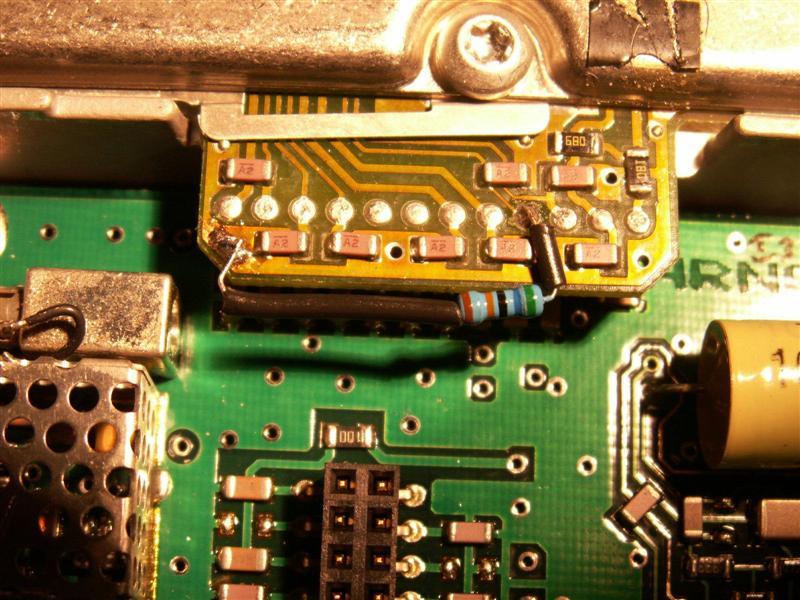
One reader had a problem with a UHF radio working at 445 MHz but he wanted it to receive a few MHz lower. He added a 560k resistor from the VCO board pin 4 to ground and that got him down to 442 MHz. Tom K8CNN supplied the following photo:
So what can you do with this information? Quite a bit, actually. If you measure the positive steering line voltage on the VCO (pin 3) at some frequency, you can raise that voltage, and get the radio to go lower in frequency while still maintaining VCO lock, by adding a resistor on the negative steering line to raise its voltage by the same amount. Let's say the positive steering line on a 900 MHz radio measures 1.5 volts when receiving 935 MHz, and you want it to receive 926 MHz. On my radio, a 1 volt change caused the VCO to move by 3 MHz. This would require the positive steering line to go lower by 3 volts, or down to -1.5 volts. We already know that the steering line voltage can't go below about +0.1 volt, otherwise the FAIL 001 message appears on the display. It certainly can't go negative. We need to adjust the steering line voltages up enough to give us an additional 9 MHz at the low end. If we move the negative steering line closer to ground by 3 volts, this will shift the positive steering line up by the same amount, and we will gain about 9 MHz of additional range, letting the receiver easily operate at 926 MHz. According to the formulas and table above, we need to move the negative steering line from -5.36 to -2.36 volts (approximately). A 220k resistor will do this for us and the radio should now receive down to about 921 MHz. This same method can be used to lower the receive capability of the UHF radio.
Acknowledgements and Credits:
Dave N1OFJ proofread the article and gave me information about the electrical placement of the 220k resistor and the alternative pin 4 connection.
Mark KD6WLY provided the photo of the surface-mount resistor. He also proofread the article. All other photos were taken by the author.
James WDØEKR tested the 5 kHz deviation modification on his radio and reported the results back to me for inclusion in this article.
Spectra, RSS, Radio Service Software, and a bunch more are registered trade marks of Motorola, Inc.
Information on the Spectra radios was obtained from Motorola's official service manuals.
Contact:
The author can be contacted at: his-callsign [ at ] comcast [ dot ] net.
Back to the top of this page
Up one level (Spectra index)
Up two levels (Motorola index)
Back to Home
Article text, layout, photographs, and HTML © Copyright 2006, 2015 by Robert W. Meister WA1MIK.
This web page, this web site, the information presented in and on its pages and in these modifications and conversions is © Copyrighted 1995 and (date of last update) by Kevin Custer W3KKC and multiple originating authors. All Rights Reserved, including that of paper and web publication elsewhere.