Up two levels (Moto index)
Back to Home
By Robert W. Meister WA1MIK
From personal experience and e-mail exchanges.
Photographs by the author unless otherwise noted.

|
Up one level (Spectra index) Up two levels (Moto index) Back to Home |
Recapping the Spectra By Robert W. Meister WA1MIK From personal experience and e-mail exchanges. Photographs by the author unless otherwise noted. |
|
Click on any of the images below to display the image at full size. And note that some are large files.
ALL Spectra mobile radios contain about a dozen small aluminum surface-mount electrolytic capacitors that have a major problem: they start leaking a nasty corrosive electrolyte out of the bottom after 10-15 years of age. Those used in mobile service that may have seen more extreme temperatures can age even faster. Since most Spectras are over 10 years old this means that they are failures waiting to happen. You need to recap the radio as soon as you get it (unless the previous owner has already done that) since the caps can be leaking with no visible operational symptoms.
Note from Mike WA6ILQ:
According to Bruce Lane, KC7GR, one dead giveaway of a capacitor problem is a "thump" or "pop" in the speaker audio as you change channels or modes (even if the squelch is closed). If the caps are bad enough the audio PA chip can be damaged by the voltage surge through the electrically (as well as physically) leaky caps.
These problem caps are located on most of the circuit boards in the radio, including the control heads. The symptoms of the damage caused by the leakage includes random problems such as the radio turning off and on for no reason, a dim display, or the display not lighting up at all, loss of transmit PL/DPL, stuck in transmit mode, erratic or no RF output power, synthesizer failures, loss of programming, noises in receive or transmit audio, pops in the speaker audio when buttons are pressed, and more. Note that the A9 (sometimes called the System 9000) control head uses different style capacitors and that control head does not suffer this problem (but the radio chassis does).
The only visible physical indication of the problem is a shiny, oozing substance on the circuit board under the capacitor. Sometimes you can see it, other times you can't (and you may need a magnifying glass or binocular magnifiers to see the leakage). This electrolyte contains Boric acid and is quite caustic, and if left on the board it can eat right through the traces; some can be patched or jumpered, but in some extreme cases you will need a new circuit board. New caps cost a few dollars; new boards cost a few hundred, if they're even available. One new module could cost you more than two or three times (depending on how good a deal you got) what you spent on the entire radio. Remember that the regular (non-ASTRO) Spectra model line has been discontinued by Motorola, and like most of their products that are 10 or more years old, spare parts are available only until the current inventory is gone.
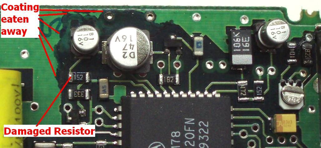
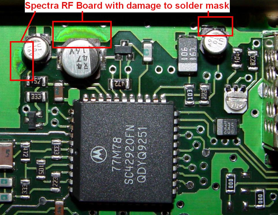
There's a green coating (called "solder mask") on the component side of many circuit boards that is used to mask off areas that aren't to be soldered during production. When the electrolyte damage is severe, it eats away at this coating or gets underneath it and corrodes the copper trace. This photo of an RF board shows the damaged area where this coating is missing (the dark area). The resistor marked in the photo was also damaged. This board was very close to being thrown away due to the damage. Compare this to the undamaged board by clicking on the "RF Board" in the table below. This photo was supplied by Jay KD6HXH:
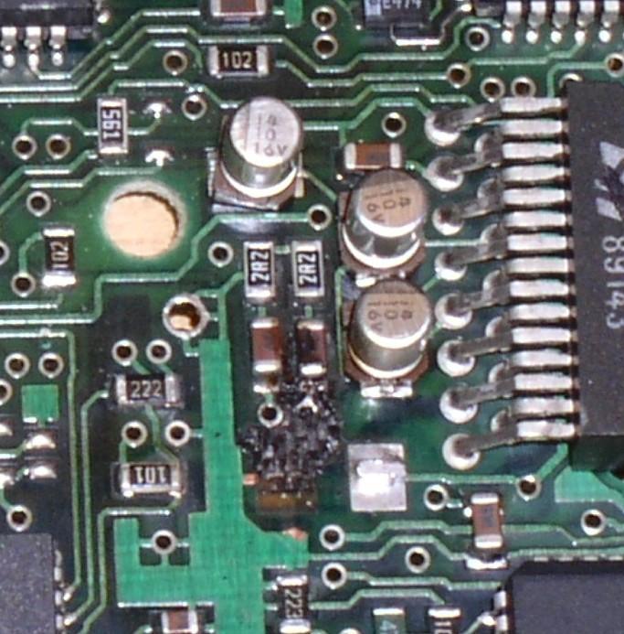
Here's a command board that has severe capacitor damage to the circuit board as well as some neighboring components. C456 used to be soldered to a foil pad over the black spot to the left of the audio PA chip. We suspect that C456 got really hot, possibly as a result of the electrolyte leaking out, and may have even caught fire. This photo was supplied by Mark N9WYS:
Mark KD6WLY reports that he's found leaking capacitors on never used, brand new, in-the-box Spectras that were built in 1991, and due to how tight the covers fit on the radio, he says "On some radios you can smell the electrolyte when you first take the cover off. And, yet on others the caps are just fine." Apparently just age kills them - they don't even have to go into service. Even if yours are just fine, I'd change them as some of the circuit boards in the Spectra are four layers thick. If any board damage makes it into an inner layer, you'll never get that board working again reliably, if at all.
You will need to remove the caps, clean the circuit board, and install new caps, and if done soon enough this will often get the radio working in tip-top condition again. Some people have put in tantalum capacitors in place of the aluminum electrolytics. These mount differently and you can't always get as large a value in as small a space. It's more important to remove the old caps than to worry about how the new ones will fit in.
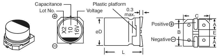
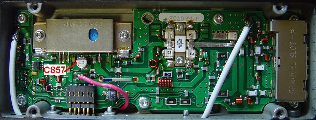
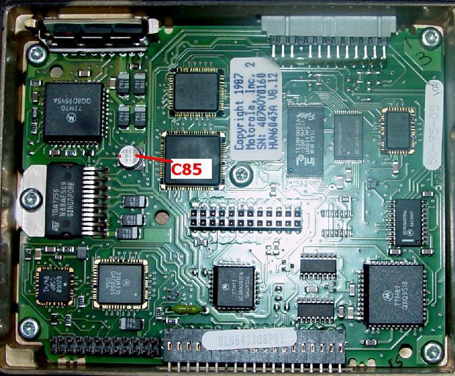
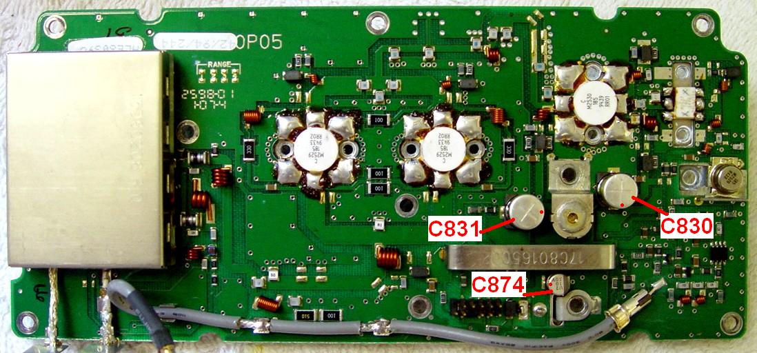
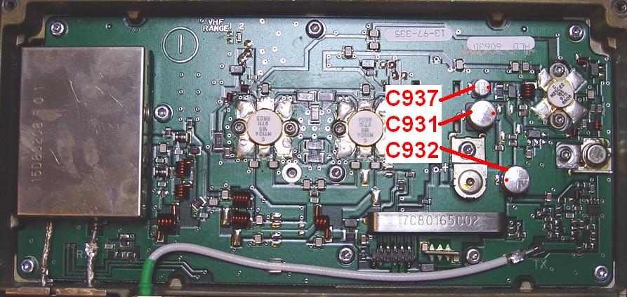
For this write-up I photographed and identified most of the capacitors that go bad, but I don't have all radio and control head models available. Even so, the problem capacitors are easily recognized: a small round aluminum can, 3/16 to 5/16 inch (4 to 8 mm) in diameter, with a brown or black plastic base. The values will be printed on top in a three-line format: the top line is a manufacturing date code / lot number), the middle line is the value in microFarads, and the bottom line is the DC voltage rating. The values shown in this article are what are installed in my radios, and the numbers match the parts list and schematic diagram in Motorola's Detailed Service Manual for the Spectra. Note that these numbers are for a 45 watt UHF radio and a 30 watt 900 MHz radio, both with A7 control heads; the parts might vary in location or value for other control heads, bands, and power ranges. If yours is different please send the information to the author or WA6ILQ so we can update this article. Please check the notes under the table below for additional details.
Aluminum surface-mount capacitors seem to have their polarity marked with a bar or band on the top over the negative terminal. I would not consider this to be reliable. The plastic base has two corners cut off at the positive end. This seems to be the universal polarity indication. An excerpt from the Mouser catalog shows this orientation:
If you aren't able to install new surface-mount components, you should be able to put in new tantalum or radial-lead electrolytic capacitors of the same value. Make sure the leads are as short as possible, observe the polarity, and orient the new capacitors so they can't short out anything nearby. You might consider gluing them to the circuit board with a tiny bit of acid-free silicone sealant, household cement, or even some form of "super glue".
After you remove the old capacitors, thoroughly clean the circuit boards for several inches around the bad caps. Isopropyl alcohol (at least 90%) is the most commonly available (and safest) cleaning liquid, but if the board is seriously damaged, you could try a solution of baking soda and water to neutralize the acid. Use a short stiff toothbrush and really work it in. Do this several times, followed by a complete washing with alcohol. Rinse the entire board to get rid of any cleaner residue. Any slight electrical leakage can affect the operation of the radio.
Here's your shopping list. You can click on any of the board names to see photos identifying the capacitors and their locations. Numbers in brackets (like [1]) refer to notes below. The Mouser part numbers in the table below were still available as of December 2011. The Digikey part numbers were provided by an unreliable source.
|
You'll have to completely remove the PA from the radio chassis and unsolder the red A+ wire to get to the capacitor on 4 and 12/15 watt radios. A 3mm hex wrench fits the cap screws in the heat sink. The capacitor on the 30-50 watt PA can be accessed by removing the PA cover and shield under the radio.
The plastic stiffener on the back of the A4 control head is held to the front with four screws and four latches, noted on the photo. You must release all of these to remove the circuit board and stiffener, then remove the stiffener from the circuit board, to access the capacitors.
In most cases, the 25 volt capacitors will be slightly larger than their 16 volt cousins. This size difference should be taken into consideration when selecting capacitors. The height is only a problem in the control head, but the actual diameter of the component may affect how it solders to the circuit board, since the pad spacing may no longer be an exact fit. Check the manufacturer's specifications thoroughly. Measure the old capacitors (diameter and height) before you buy new ones. The Mouser parts listed above are the same size and value as the originals and cost about $0.25 each (that's about $3 in parts for the entire radio).
Some of the copper traces are very small and can be broken if you pull the components off without thoroughly melting the solder. Removing the circuit boards from the radio makes it easier to work on them but it increases the repair time. Observe and follow electrostatic protection precautions. Surface-mount components such as these may require hot-air rework stations to be removed and installed properly, as the soldered connection is underneath the capacitor and not accessible by an ordinary soldering iron. However, few of us actually have the right equipment to do this. If you're lucky enough to know someone who does, perhaps you can get them to do the job for you. The two people (listed below) will replace all the problem capacitors and repair damaged boards (to some extent) professionally; they can be found on various news groups and elsewhere on the web.
My own personal preference is to replace the capacitors with ones of similar value and geometry, so the board looks like it came from the factory. Without the right equipment, radial-lead caps are a good alternative, although you may have to cut the leads quite short and position the parts to minimize interference. Rather than forcing people to do it one way, I'm presenting several points of view so the reader can make an educated decision whether to tackle this job on their own, or send the radio to a professional of their own choice.
SMD capacitors are very light weight. The Spectra circuit boards aren't designed for thru-hole components, which are typically larger. With the vibration present in a mobile installation, the leaded components may flex and move around, putting undue stress on their leads and the thin copper traces. For these reasons, I'd rather use the SMD parts, even though they are harder to work with. You can use a small dab of hot-glue to secure leaded parts to the circuit board.
One of the people who repairs two-way radios for a living and works on Spectras almost every day replaces these capacitors with the Panasonic "HD series" capacitors. These are rated for 5000 hours, 105C temperature. They are sold by Digi-Key. Nichicon "UUD series" caps have the same ratings at the Panasonics, but not as wide a selection of capacitance and voltage. Nichicon is available from Mouser; lead-free part numbers are shown in the table above. There are no 105C temp SMD electrolytics at Jameco. Other possible sources include Newark and Allied. The Mouser and DigiKey prices are between US$0.25 and $0.75 each.
NOTE: Be very careful with tantalum capacitors. The marking convention is NOT universal. Some have a bar over the negative end; some have a bar over the positive end. Some have a notch on one end or the other. Some have a chamfered corner or edge. Check the exact manufacturer's spec sheet for the components you buy and be sure you know the polarity before you install them. One reader had a couple of new tantalum capacitors go up in flame 15 seconds after the radio was turned on; I'm sure that was a heart-stopping experience. Turns out they were marked differently than some other tantalum caps on the board. Never Assume.
Recently I discovered another article that covers recapping/refurbishing very nicely. This offsite article, courtesy of David AI4JI, has tons of action photos and progress shots. The author also sells complete kits of replacement capacitors needed to handle Spectra mobile radios. You can choose SMD, through-hole (leaded), or tantalum components.
There are several brands of leaded capacitors available on Mouser and other mail-order suppliers. These come in a variety of physical sizes and temperature ranges. Given a choice, go with 105C temperature-rated parts. The radio should never get this hot but these parts seem to be of a higher quality. You can use 25V caps in place of the 16V caps but they're usually a bit bigger. Space is only an issue on the control head, under the plastic stiffener, but if you leave the leads a bit longer you can position the caps in an area with a bit more room. Note that longer leads also add some inductance to the circuit so try to keep them 1/4 inch or less; just enough room to solder them to the boards.
Tim KCØLXL sent a list of suitable radial-lead capacitor part numbers. These are all Nichicon brand and are Mouser part numbers.
Bruce KC7GR has the following recommendations:
For the most part, I tend to stick with SMD aluminum electrolytics. I tend to favor the Panasonic HD series parts. For the small 10uF/16V parts, the DigiKey P/N is PCE4949CT-ND, Panasonic P/N EEE-HD1C100AR. These are best bought in quantities of 50-100 pieces, as the pricing per unit is much better than just buying singles.
For the larger 10uF/50V parts, you'd want PCE4976CT-ND, Panasonic P/N EEE-HD1H100P. And, finally, for the 47uF/16V part, order PCE3340CT-ND, Panasonic P/N EEV-HD1C470P.
When replacing one of these caps with a leaded part, the best advice I can give is to choose a radial-lead solid tantalum part of the same capacitance value, but slightly higher voltage rating. Example: for the 10uF/16V parts, I would choose 10uF/25V in tantalum. For the 10uF/50V parts, it should be OK to stick with the same voltage rating. Same for the 47uF part. A good rule of thumb is it's always safe to use a higher-voltage rated cap, but never go below the original part's rating.
Replacing these components:
Note from Mike WA6ILQ:
Before you try this procedure, I recommend that you acquire a pair of binocular magnifiers. Harbor Freight Stores has a useful and inexpensive clip-on (under US$8) that belongs in the tool kit of anyone who ever pops the cover off a radio. There are much better ones out there that cost a lot more money, but as often as I need one this set works quite well. The other Harbor Freight model advertised "with lights" next to the eyepieces is not worth it: the AAA cells don't last, the light is not bright enough nor is it focused on the work, but if they are out of stock on the first model, you may be stuck with the second (just ignore the lights, leave the batteries out). If you plan on wearing it for any length of time one modification is necessary: add one or two thicknesses of felt on the inside of the headband where your forehead skin comes in contact with it. In my case, at least, the vinyl plastic got very uncomfortable after a half-hour or so but the felt resolved that annoyance immediately - now my eyes need a break long before my skin starts to itch. I just took a piece of felt sized to fit around the band and overlapped it on the outside of the band, and added Velcro at the overlap point (but a safety pin or two would work just as well). When the felt gets full of sweat I peel open the Velcro and toss the felt strip into the washing machine along with the week's dirty socks.
Mandatory disclaimer: I have no financial interest in Harbor Freight; I'm just an occasional retail customer.
The following section and photographs were supplied by Mark KD6WLY.
"...there is a small mention of front panel display going bad or dimming. Those two metal can electrolytic caps often leak and can foul the board as well as fail. When they fail the display goes dim or out. Even these radios that are "brand new" have had some failed electrolytics due to age so I just replace them with tantalums while I'm in the radio making other modifications. I've been replacing them with surface-mount capacitors but you have to be VERY careful removing the old caps. I destroy the old cap by prying the can off its leads between the plastic insulator and the can, then I carefully break off the plastic insulator and clean the board with isopropyl alcohol, THEN unsolder the two leads from the pads on the board. I use an 18 watt small iron and a BIG magnifier light. Another secret is to use liquid flux on the end of a very small screwdriver or toothpick to flux the pads as well as the new part."
Click on any photo below for a larger image.
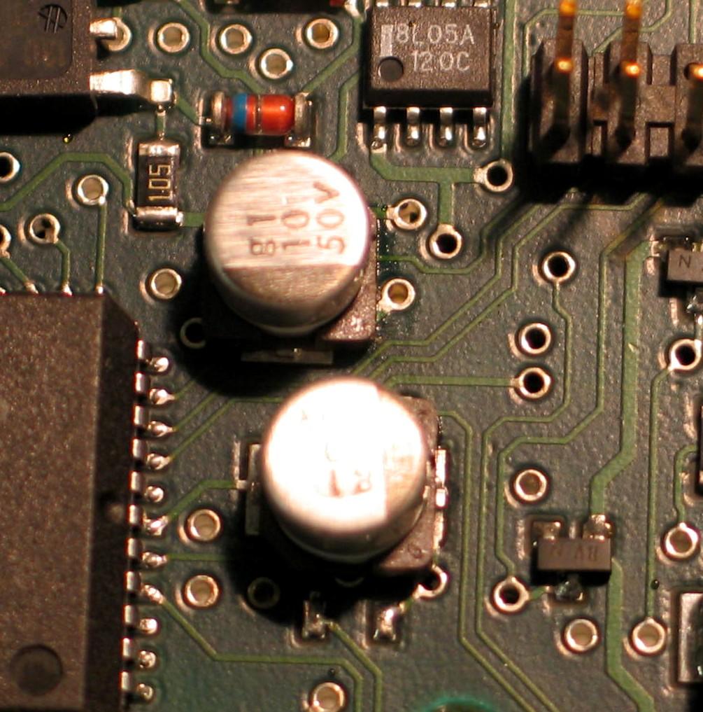
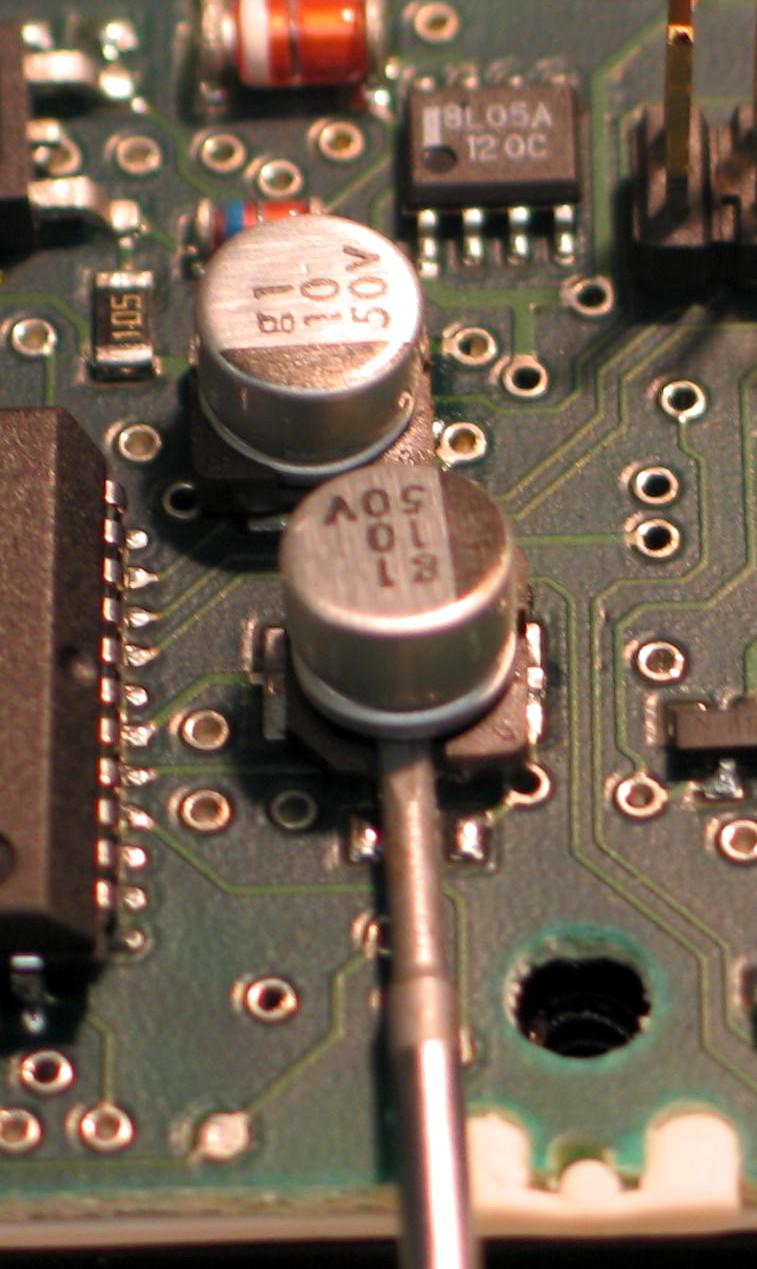
Here's a control head with leaking capacitors (look just to the right of the
plastic base of either cap). It's almost invisible on the lower cap, but it's
there - just keep reading. This is why you want the binocular magnifiers.
Here's where to separate the aluminum can (and the guts) from the plastic base with
a small screwdriver (the cap is bad anyway, it's the safest way to avoid damaging the
board). Just put the tip under the body between the two leads and above the plastic
disk, then pry up, tearing the body of the cap off of its leads.
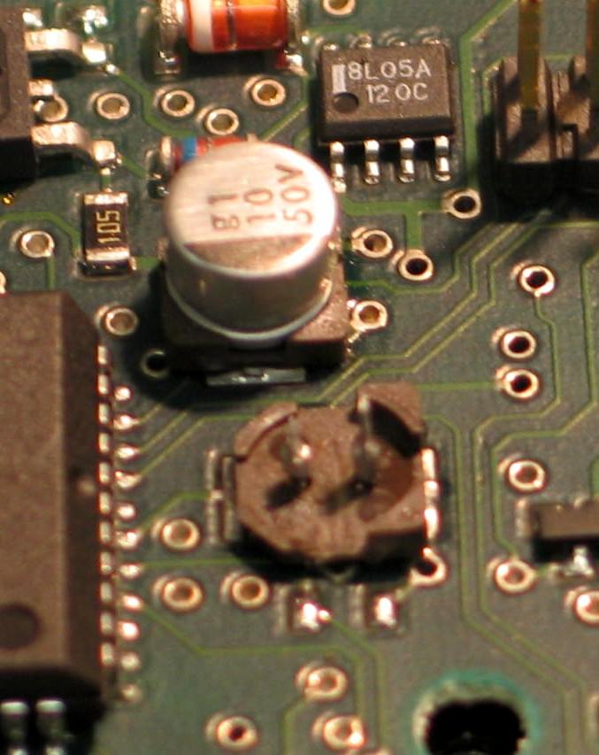
Here's what's left of the first cap - just the base and the two leads that used to
connect inside the capacitor. You can see the dried electrolyte leakage as a dark spot
on the plastic base. Now remove the plastic base, and then touch each lead with a
soldering iron to remove them from the circuit board.
If you will be installing new caps, you might have enough room to solder tantalum capacitors in place of the old aluminum electrolytic ones. In most cases, the physical size of the new component is not important, so you could use leaded components. The one place where height does matter is on the control head, because a plastic frame is mounted over the top of the capacitors.
Note from WA1MIK:
One of the two control head caps has about 40 volts across it, so you really want to use a 50V capacitor here, either tantalum or aluminum. The rest are not as critical.
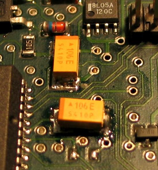
Here's a photo of the two new tantalum capacitors installed on the control head circuit board.
Note from WA1MIK:
Mark informs me these are Digi-Key part number 478-1700-1-ND, 10uF at 25V. After reading this article, he agrees that 50V capacitors are necessary for the control head, and he will be looking for some that will fit this tight space.
Update by Mark in early 2007:
Here are the three part numbers that I have been using. These are all manufactured by Kemet and are Tantalum SMDs. These three numbers will do the entire radio, not just the head.
T498D106K050ATE1K0 10uF 50v 150c
T495D476K020ATE170 47uF 20v 105c
T498B106K016ATE2K8 10uF 16v 150c
These are Mfg p/n so just add "80-" in front to make a Mouser p/n.
Note from WA6ILQ:

The Spectra is not the only electronic device to suffer this problem...
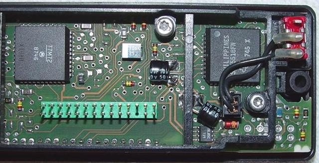
Here's a photo of an Apple PowerMac 6500/225 motherboard (1997 build date) that
uses 18 of the same type of cap... the photo only shows 4 of them.
Note from WA1MIK:
A friend was having multiple problems with his Spectra radio: dim display, hum/buzz in the audio, and it took more than 30 seconds to complete the self-check and become usable. He removed the two 10uF 50V capacitors from the control head and installed some radial-leaded electrolytic caps in their place, Mouser p/n 140-L50V10-RC. These are ultra-miniature aluminum components that cost less than $0.20 each. They're about the same size as the surface-mount caps, but are much easier to install due to the leads coming out the bottom. You'll have to be creative when you install them so they don't interfere with the plastic stiffener on the back of the control head. Use some sleeving over the leads if they need to be more than 1/4 inch long. There's plenty of room to lay them on their side so they clear the stiffener's ribs. After the new caps were installed, the display resumed its normal brightness level, the hum/buzz disappeared, and the radio becomes fully operational in about 3 seconds.
I performed the same procedure on my own Spectra A7 and got similar improvements. I was able to remove the original capacitors by heating each lead alternately for a few seconds while rocking the capacitor to lift it off the board. Two or three tries on each side was all it took, and it popped right off. I added a dab of solder to the pads, cut the leads to fit, added a dab of solder to each lead, and set them into the puddle of solder on the board. Here's the control head board repaired with these tiny radial-lead capacitors. Compare this with the original photo by clicking on the "A5 or A7 Head" in the table above.
There are traces running between the capacitor's solder pads on the A2/A5/A7 command board. Leaky electrolyte can damage these, causing loss of segments or digits on the display. If you have such a problem, this is more than likely a result of leaky caps, so when you replace them, carefully check the signal continuity of the traces under the caps. This doesn't seem to be an issue anywhere else in the Spectra radio.
The following photo was supplied by George WA1QGU, who was trying to fix a display problem. He found the damaged foil after removing the capacitors. He installed leaded components rather than surface-mount ones. Click on the photo for a bigger image.

Testimonials and User Experiences:
WA1MIK received the following unsolicited e-mail:
Just wanted to drop you a line to thank you for your article on replacing the electrolytic caps in the Spectra. I had seen what I thought were isolated capacitor failures, but was unaware how prevalent the problem is until reading your article.
I had 15 800 MHz Spectras in the shop that were "Dogs"; radios that had strange, hard to nail down problems. Having nothing to lose, I replaced all of the caps in these radios. I was surprised, when I removed the caps, to find visible leakage under about 25% of them! To make a long story short, simply replacing the capacitors restored normal function to all but three of the radios!
I normally shun the "shotgun" approach to repairing radios, but with this rate of failure/success, simply taking the half hour to change $6-$7 worth of capacitors is very cost effective. We have several hundred Spectras in service, and we could re-cap them all for about the cost of a couple of replacement radios!
Thanks again for sharing the information; it's saved me a lot of time and grief!
Steve, Senior Communications Technician, Oakland County, MI
He provided the following details as well:
These radios were purchased by us in 1991/1992. All of these particular radios were used in vehicles; I still have a few that came out of Consolettes that I still need to get to.
The worst leakage was near the 47 uF cap to the rear of the RF board, and was almost identical to the photo in your article. A couple radios also had damage (corrosion) to the 82K resistor visible in the upper right corner (next to the perforated shield), but oddly there was no visible leakage or damage to the PC board between the nearest 10uF cap and the resistor.
I used the part numbers you provided to order the replacements from Mouser; thanks for saving me the trouble of having to look them up myself! Worked great.
On the last batch of radios that I repaired, I did deviate from the above parts list in that I used a 10uF/25V tantalum to replace the 10uF/16V factory electrolytics. The reason for the substitution is that the tantalum cap is physically smaller, making it easier to install, especially in the tight spaces near the audio IC [on the command board]. The Mouser part number for this cap is 74-595D106X9025B2T and they cost about $1 in early 2007.
Thanks again!
Steve N8NM
I couldn't have said it better myself (and I didn't). Thanks, Steve!
I have a Spectra desktop station that had severe popping sounds coming from the speaker whenever any control head button was pressed or the receiver opened squelch. It also would make crackling sounds just sitting there squelched up. The display was also rather dim.
I replaced the two capacitors on the control head but these made no improvement. I did notice a shiny substance underneath the plastic base of one of these capacitors, so it may have just begun to leak.
I then replaced the four capacitors on the command board; ALL of the popping went away. The radio is now so quiet it sounds better than some of my newer Spectras. The only thing you hear is a nice clean beep when you press a button.
After removing the command board's capacitors, I noticed some dark brown plastic compound on the board. It would soften when heat was applied, but was not crystalline like cold flux would have been. I was able to scrape it off and cleaned the board with alcohol. No damage was found on the circuit board, but I believe the capacitors were just starting to leak, or else the process of unsoldering them caused some of the electrolyte to leak out. None of this stuff was visible until I removed the capacitors.
Note from KC7GR:
Fair warning: Don't limit your efforts to the command board. Do the RF board caps as well, even if they look clean! What you described is indeed signs of electrolyte leakage and subsequent corrosion. If the command board caps failed, those on the RF board cannot be far behind.
I obtained more 10uF 16V capacitors and replaced the four on the RF board. I found a slight bit of discoloration of the green solder mask in one area, and a couple of the solder joints were dark gray in color, almost like the solder had crystallized. One capacitor had just started leaking. These have all been replaced. The date codes on the ICs were late 1993, so the board was about 14 years old.
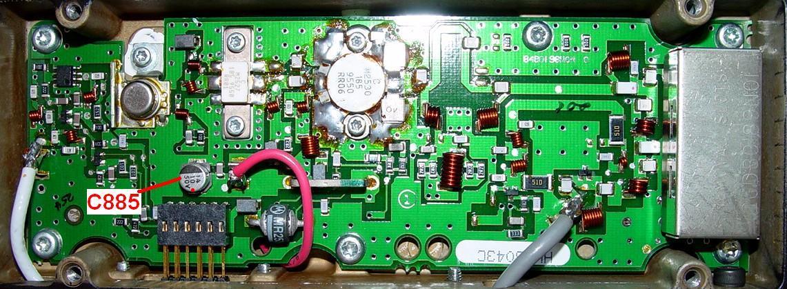
A friend has a VHF 50w radio that was giving him intermittent FAIL 001 messages. He thought it was because he had a couple of 145 MHz frequencies programmed into the radio (the normal operating range starts at 146 MHz). He gave me the radio to work on. I measured the VCO Steering Line at 9.3V; normal range is 1-8V. After a while, the FAIL 001 messages disappeared and the steering line came down into the 1-4V range, but changing modes would force it back up to 9.3V and the messages appeared on the display. I took a good look at the RF board; then took some photos. Click on either one for a bigger image.
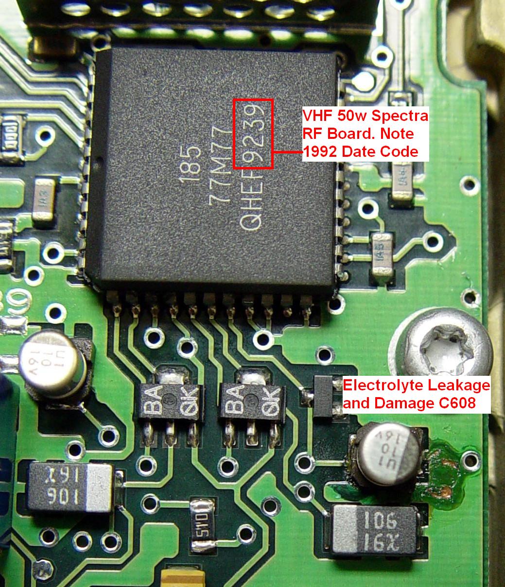
Note the date code on the nearby ICs; this radio is 15 years old and there's definitely visible damage to the solder mask (that green coating on top of the copper). I don't know if there's also damage under the capacitors. I'm sure the caps and damage on the command board are similar. This radio will need ALL its electrolytic caps replaced.
After removing the five capacitors on the RF board, I was able to remove the leaked electrolyte from the board, but three solder pads lifted off the fiberglass substrate during the cleanup process. A small dab of Super Glue was used to adhere them back to the board. Short pieces of #30 wire were used to repair the broken traces going to the positive pads at C608, C635, and C636. No other damage was observed. New capacitors were installed and the FAIL 001 messages are all gone, even on the 144 MHz frequencies. The receiver sensitivity is 0.35uV for 20dB quieting. This part of the repair and checkout took about an hour.
The single capacitor on the PA board plus the four caps on the command board were easily replaced. No leakage was evident on these assemblies. Two more pads lifted off the board during parts removal and had to be repaired. After the new caps were put in, the radio worked fine and there was more receive audio as well. This part of the repair took another hour. The 10 capacitors cost about $3. Add another hour to check out the radio (transmitter deviation, power, and frequency, receiver sensitivity).
I had an A5 head that would power up the radio and go through the self-check, but the display was so dim, it actually could barely be seen. It would then fade away to nothing after five seconds of operation. None of the other pushbuttons worked either. Replacing the two 10uF capacitors made the unit rock-solid again, although the display is not quite as bright as some of my newer control heads. (I suspect the display just wears out after a while and doesn't achieve full brightness due to old age.) I also thoroughly cleaned everything; this fixed the intermittent button problem.
Another UHF Spectra didn't exhibit any audible or visible capacitor problems, but the owner asked me to replace them anyway. Upon removal of the caps on the command board, I found some white powder underneath two of the four caps, shown here:
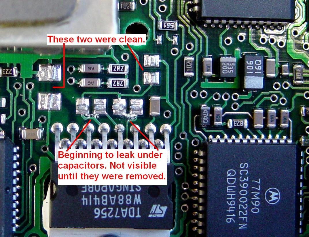
On the RF board, the only evidence was a slight discoloration of the green solder mask next to one capacitor:

The residue on both boards cleaned up easily with alcohol and a toothbrush and new capacitors were installed. Note the date codes on the nearby ICs; from what I've observed, radios that are 13 or more years old definitely have leaky capacitors and they all must be replaced.
Soldering tools and technique are critical to a successful job. I haven't found the right combination just yet, as I've only recapped one VHF radio and half of a 900 MHz radio so far. My procedure or lack of experience may be contributing to the cause of the solder pads lifting during capacitor removal, which leads to broken traces that must be repaired.
After recapping another couple of radios, I think I've found a method that works well for me. I don't bother trying to unsolder the capacitors; the alternate heating of the leads puts too much stress on the solder pads. I just grab the cap with my needle-nose pliers and slowly rock it back and forth at right angles to the two leads until they break off. This takes perhaps 30 seconds. I don't pull on the cap, just bend it from side to side gently as far as it will easily go. As the leads start to give way, the cap can be bent further and further, until the leads just snap off. Then I pull the plastic base off and remove the remaining component lead and excess solder from the solder pad. I haven't lost a pad yet with this process.
Because most of the capacitors are around the perimeter of the RF board, I have found that it's easier to work on this board by removing it from the radio first. This involves removing the VCO screws and lifting the VCO enough to unplug it from the RF board, removing the coaxial cable going to the front end, and removing seven screws that hold the board to the chassis. It then can be unplugged from the command board and it lifts up and out.
For installing the new ones, first I check the placement of the new component to see how much solder pad will be accessible when the new part is in place, and try to center it. Then I add a drop of solder to one pad, the one that will be least accessible, I heat this pad up once more and place the new capacitor flat into the molten puddle, making sure that the part is positioned to give me access to the other solder pad. I tug on the cap to make sure it is actually soldered. Once one lead is done, I heat the other pad and add a dab of solder to the junction of the pad, exposed lead, and soldering iron tip. The solder seems to wick up into the joint when done properly. This procedure seems to work well for me, but your mileage may vary. The iron is set at a temperature of 700F and the tip is 1/32 inch in diameter, although it seems bigger than that.
I just obtained a 50w VHF radio with an A7 control head. It seemed to work nicely and was very clean inside and out, however: I had difficulty reading the existing code plug, I could not access the service menu via the control head, and when trying to make any changes to the alignment settings, the software kept giving me warning messages about not hitting buttons on the control head during this procedure. The squelch sounded like it was right on the threshold; constant yet intermittent noise bursts were coming from the speaker.
I tried another A7 control head and that got rid of all of the problems mentioned above.
I replaced the two electrolytic capacitors on the original control head and that fixed it right up. There was just a slight bit of dried electrolyte on the circuit board, underneath the capacitors, which was not visible until I removed them. None of the other capacitors are showing any other signs of leakage either. The radio is quite old; some of the date codes on the ICs are 1989. I will be replacing all of the caps in the radio shortly.
I acquired a 900 MHz, 30 watt, remote-mount, 1992 vintage, B7 radio. The display brightness wasn't quit up to par, the receiver squelch noise was barely audible, and the "beep" tone that sounds when any control head button is pressed was just a series of soft clicks, but the radio did work. Physical examination of the control head showed leaking electrolyte around one capacitor; a couple of caps on the command board were leaking, but everything looked fine on the RF board and PA.
Replacing the caps on the control head didn't improve it one bit; it seems that the vacuum fluorescent displays (VFD) just get dim after a while, and replacement is the only cure. I had the same AC and DC voltages in the 35V supply before and after repairing it, but at least the leaking electrolyte is gone.
While removing the bad caps on the command board, I found at least one lead that had been eaten through, effectively disconnecting the capacitor from the circuitry. Another cap had leaked enough electrolyte to leave a green spot on the solder pad. All of the solder had crystallized and turned a dull gray, and was difficult to remove; the soldering iron just couldn't make contact with the powdery substance to melt it. After removing the caps, lead pieces, excess solder, and cleaning the board, I found nothing missing or eaten away. Here's a photo of the circuit board after removal of the caps:
New capacitors on the command board brought it right back to life. The audio sounded clear and loud, and the beep tones were back to normal.
I programmed the radio with the 900 MHz repeaters in my area and discovered that I did not have to modify the VCO to get to those frequencies (i.e. I had no FAIL 001 messages). Even though the capacitors on the RF board show no physical or operational signs of leaking, I will replace them anyway. Also notice the brown coating on some of the audio PA IC leads; read more about this at the end of the article.
Another A7 control head wouldn't light up at all. I had removed the two capacitors and replaced them with leaded ones (because that's all I had in stock at the time), but that didn't help. Eventually I put the circuit board on an extension cable and started probing around. I couldn't find the +35VDC supply on one of the two caps. I started tracing the circuit and found one foil right next to that capacitor that had gotten eaten away. I bridged it and the display came to life. I then discovered that neither the HOME or DIM buttons worked. I traced that to another foil that ran right next to that same capacitor. I didn't bother finding the exact break but just ran a piece of wire from one feed-through hole to another. In this case, it was easy to find and work on the bad areas because I had not installed a surface-mount capacitor.
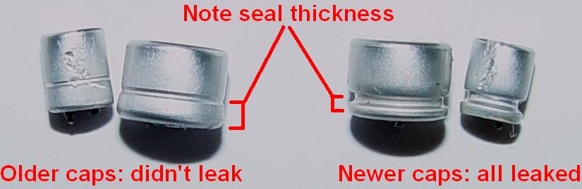
I was given four dash-mount radios to re-cap. All were working when I received them. One radio was 1989 vintage, yet NONE of the caps had leaked. I did notice that these seemed to be of a different design than the other ones; they were taller, and the crimp was higher. See both designs in the photo below. Maybe they have a better seal; it's certainly a bigger seal. One VHF radio had November 1997 date codes on it. None of the capacitors showed any visible leakage on the circuit board, however when they were removed, every one had leaked under its plastic base. One solder pad came unattached from the command board. So 11 years is already too late for some radios. It cannot be stressed enough: when these caps leak they cause unseen damage.
If you're not thrilled with soldering surface-mount capacitors, you can use electrolytics with short leads. Just make sure you get caps that are physically able to fit into the space. Diameter isn't usually the problem; height is. You might have to bend the caps over on their sides to make them fit. While not "stock", any new capacitor is better than the old leaky ones. Here's an example of a command board with leaded caps; note that the leftmost cap (C456) is missing and there are very loud audio clicks coming out of the loudspeaker.

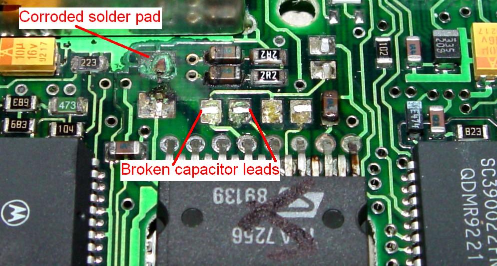
Here's a UHF RF board that had some damage done by the leaking electrolyte. The repair isn't pretty but it works.

The filter cap on the 100w UHF power amplifier also got replaced. It's a bit too tall for me but it barely fits.

Another Problem Area:
It seems the electrolytic caps aren't the only parts used in Spectras that can get leaky; the audio PA IC seems to exude some tar-like substance. I found this tidbit and photo on the web:
"I have new caps on order for my Spectra to fix the popping audio... but there's also a bit of noise in the speaker whenever the audio amp is on. It seems to be temperature and humidity dependent. Do bad caps do this too or is something else dying on that board?"
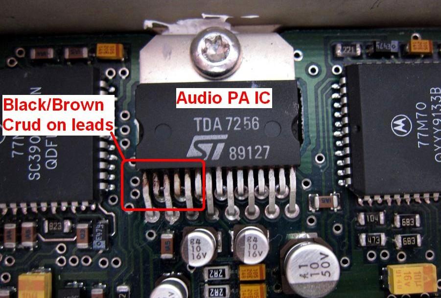
Look at the leads of the audio PA chip. If there's some black gunk on them, right next to the IC's plastic body, you need to replace the audio IC. These chips will exhibit hissing and a popping noise when they start to go bad. I've even seen them ooze significant amounts out the legs, hence the blackness on the legs. This is not to be confused with tarnished silver legs. It looks like tar, and can be cleaned off, but of course that doesn't fix the problem. So much for hermetic sealing. Notice that this same stuff is visible on another command board photo above, the one from the 900 MHz remote-mount radio
Acknowledgements and Credits:
Mark KD6WLY supplied the photos of the control head caps being replaced as well as the suggested method of removing them.
Bruce KC7GR also recommends Panasonic HD capacitors.
Jay KD6HXH supplied the photo of the damaged RF board.
Mark N9WYS supplied the photo of the damaged command board.
George WA1QGU supplied the photo of the damaged A7 control head board.
Tim KCØLXL supplied his list of radial-lead capacitors as alternates to the surface-mount parts.
The notes from Steve N8NM were unsolicited but definitely well appreciated by all involved with this article! Sometimes we authors get so depressed wondering if people actually read our stuff.
Component values were obtained from the Spectra Detailed Service Manual, part number 68P80102W61.
Apple motherboard photo by Mike Morris WA6ILQ.
Contact Information:
The author can be contacted at: his-callsign [ at ] comcast [ dot ] net.
One source of Spectra repairs is Bruce Lane, KC7GR who has a radio shop in Kent, Washington. Assuming no other problems, he can recap a Spectra for anywhere from $75-$130 (2006 prices) plus shipping, depending on the extent of the damage (if any) and if the audio PA chip needs replacing. He also offers programming and other services. See http://www.bluefeathertech.com/ for his web page and click on 'RF Services'. In other words, he can take that eBay Spectra (or any one of several other radios) and your programming list, recap it, program it, test it for sensitivity and power out and ship it back to you all ready to install in your vehicle with zero concerns.
Back to the top of the page
Up one level (Spectra index)
Up two levels (Moto index)
Back to Home
This article first posted 26-Jul-2006
Spectra radio circuit board photos and most of the article text © Copyright
2006 by Robert Meister WA1MIK.
Control head capacitor replacement photos and text © Copyright 2006 by Mark
Hergesheimer KD6WLY.
Hand-coded HTML © Copyright 2006 and date of last update by Mike Morris WA6ILQ.
This web page, this web site, the information presented in and on its pages and in these modifications and conversions is © Copyrighted 1995 and (date of last update) by Kevin Custer W3KKC and multiple originating authors. All Rights Reserved, including that of paper and web publication elsewhere.