Up two levels (Moto index)
Go to the Home page
Control Head Ignition Jumpers
By Robert W. Meister WA1MIK
|
Up one level (Spectra index) Up two levels (Moto index) Go to the Home page |
Spectra Mobile Radio Control Head Ignition Jumpers By Robert W. Meister WA1MIK |
|
Enough people have asked for this information that it seemed logical to post something about it. This is specifically for X5 / X7 dash-mount control heads. Remote-mounts have different options via orange and green wires coming off the back of the control head. I have included that information at the end of this article. See Mike Blenderman's very extensive Spectra web site for more information.
The Official Documentation:
Two jumpers inside the control head govern how the radio will operate. This "Table of Operations" and the text that follows, comes from the Spectra Detailed Service Manual:
|
The ignition cable is the fused red wire attached to the accessory connector. The control head is shipped with jumper JU1 out and jumper JU2 in. Configured this way, connect the ignition cable to:
"battery hot" on the fuse block to TRANSMIT and RECEIVE via the front panel pushbutton ON/OFF switch, regardless of the ignition switch setting (TYPE 1);
or,
"ignition" at the fuse block to disable TRANSMIT and RECEIVE except when the ignition switch is ON. This method is more convenient because you need only to switch off your ignition... the radio will not drain your car's battery when you leave the radio switch "ON" (TYPE 2).
If the customer wants to inhibit TRANSMIT, but allow any RECEIVE (TYPE 3), the two control head jumpers must be changed. Remove the two front panel screws, one from each end, and then pull straight out on the control head to detach it. The jumper locations on the PC board are shown in the foldout toward the end of this section. Locate jumper JU2, carefully un-solder it, and remove it from the board. Find the location for JU1 and solder a jumper in place. Install the control head. Connect the ignition cable to "Ignition" at the fuse block.
My Own Observations:
The two screws holding the control head to the radio are 2.5mm hex head, but a T10 Torx driver fits perfectly and is recommended. You will also have to remove the plastic stiffener on the back of the control head to gain access to the two jumpers. A T10 Torx driver will remove the silver screws holding the control head together.
The jumpers themselves are actually zero ohm surface-mount resistors. You will see "000" on these little black things. If you were looking for traditional PC-style jumper blocks, now you know why you couldn't find them.
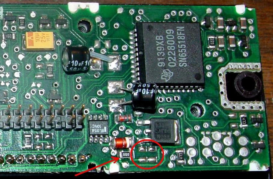
There are several revisions of the control head circuit board. I've taken photos of the two I have, and they're shown below. The jumpers are indicated with red arrows; the areas in which they would be installed are indicated with red circles. Click on any of these photos or images for a larger view.

This board seems to match the following layout for a W5 / W7 control head found in an Astro Spectra Control Head Manual:
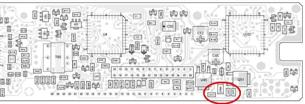
This board is a bit different, possibly older. Note that it has had its two surface-mount "time-bomb" electrolytic capacitors (C45, C52) replaced with new radial-lead components:
As you can see, the jumpers are pretty much in the same location once you know what to look for. Here's the component layout for an A5 / A7 control head found in the Spectra Detailed Service Manual:

Remote-Mount Control Heads:
I found this information in a Spectra Installation Manual. The Green wire operates the Receiver; the Orange wire operates the Transmitter.
| ||||||||||||||||||||||||||||
Forced Turn-on:
Two people recently inquired if it's possible to configure a Spectra radio so it turns on when power is applied, without having to push the ON/OFF button. There's nothing documented in the service manuals for this, but I was able to find that JU7 controls this feature.
JU7, if installed, will cause the radio to power-up if voltage is applied to both the main DC connector as well as the ignition control wire. The power cable I use has both of these wires connected (see the Spectra Low/Mid Power Cable article in this section). The entire radio's operation is now dependent on the presence or absence of voltage on the Ignition Control line feeding the radio, but you obviously still need main power for the radio to function. You still have Ignition Control to enable/disable TX and RX, but this same line now turns the whole radio on and off.
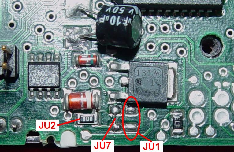
To get to this jumper, you need to remove the control head and the plastic stiffener from the back of it. I soldered a short piece of #30 wire across the two pads on the back of an A5/A7 control head, reassembled the unit, plugged it into the radio, then applied power. The radio came right on and the ON/OFF button had absolutely no effect. The jumpers are identified in the photo below. Note that JU2 is a factory 000-ohm resistor while JU7 is the piece of wire I added. JU1 is NOT installed.
The radio will power up in its default state: HOME mode, default volume, default display intensity, coded squelch, etc. It loses its memory (last mode, volume, etc.) when ignition and main power are lost.
Acknowledgements and Credits:
Spectra and Astro Spectra are trademarks of Motorola, Inc.
All circuit board layouts came from official Motorola Spectra service and installation manuals.
Contact Information:
The author can be contacted at: his-callsign [ at ] comcast [ dot ] net.
This page was created 06-Jan-2007.
Back to the top of the page
Up one level (Spectra index)
Up two levels (Moto index)
Go to the Home page
Article text, photos, artistic layout, and hand-coded HTML © Copyright 2007 and date of last update by Robert W. Meister WA1MIK.
This web page, this web site, the information presented in and on its pages and in these modifications and conversions is © Copyrighted 1995 and (date of last update) by Kevin Custer W3KKC and multiple originating authors. All Rights Reserved, including that of paper and web publication elsewhere.