Comments / critiques / suggestions / corrections / updates for this page are welcome and appreciated.
(Actually to any page at this web site!)
Attention EBay buyers
No matter WHAT the label on the radio (or the seller)
says, no Spectra will ever operate over the entire 136-174 MHz (high
band) or 403-512 MHz (UHF) frequency range. Each
unit will do only a portion of that band's frequency spread, and that
portion is called a "split", a "bandsplit" or a
"range". The VHF units were made for 136-162 MHz (rare)
or 146-174 MHz (common). The UHF units were made for
403-433 MHz (very rare),
438-470 MHz (common),
453-488 MHz (rare),
450-482 MHz (common), or
482-512 MHz (very rare).
You can stretch things a little and go a megahertz or maybe two out of range
and that's about it. If you buy the wrong range radio for your application
(for example a 403-433 MHz and you want to use it on 440-450 MHz
amateur frequencies, or a 482-512 MHz radio for GMRS) it just won't work
and you will have a nice doorstop. Despite what you see on eBay there is not (and
never was) a 406-440 MHz range. And it is not practical to
range-change a Spectra or Astro-Spectra radio. For more information scroll
down to the section titled "Splits / Ranges".
Another note: Spectras are wideband only (±5 kHz) on VHF and
UHF and narrowband only (±2.5 kHz) on 900 MHz.
You probably could hack and slash at a Spectra and make it to where it
would work in a narrowband environment, but it would be narrow only, not
switchable. Plus it would not be type accepted and would not be legal. If you
need a narrowband radio and want to stick with the Spectra line
then you will have to find an Astro Spectra.
|
The Spectra line was MD'd (Manufacture Discontinued) in the early to mid 1990s
and depot maintenance terminated several years later. Many public safety agencies
nationwide were forced into new radios (if they stay with Motorola it's usually the
MCS2000 series) and large quantities of Spectras are in surplus. They are wideband
will be illegal to use in commercial and public safety use when the narrownand
rules go into effect. Once you replace the "time bomb" capacitors (under
US$10 in parts, see the article "Recapping the Spectra Mobile" in the Spectra
section) you can end up with an excellently performing mobile radio at a decent
price (new they were $1500 to $2000 each, sometimes higher, depending on the
options). And the intermod performance alone is many times better than any
Japanese-built amateur grade radio.
The Astro Spectra was a follow-on design that used most of the accessories,
most of the cosmetic parts, a few of the circuit boards, but was very different
inside (but it unfortunately still used the "time bomb" capacitors). One of the
differences was in the synthesizer as the Astro could do the 6.25 kHz steps
(where the smallest the Spectra could do was 12.5 kHz or 20 kHz steps),
another was a much more powerful microprocessor that suported digital audio in
multiple formats like VSLEP (Moto proprietary) and IMBE / P25 (the
"Project 25" digital audio standard that is supported by several
manufacturers). You will want to be very careful when purchasing any surplus
Astro / digital radio. It isn't always what it seems to be.
A good percentage of the surplus stuff hitting the market is not IMBE but older
(proprietary) VSELP modulation and some of the Astro radios are flashed
(i.e. contain firmware) for analog only (i.e. won't do digital at all). Since
VSELP is not an open standard the popular opinion is it's not legal on the
amateur bands much like GE / Ericsson / Ma-Com AEGIS, EDACS
and Pro-Voice. The only way to tell is check the flashcode, and once you have
that you will need to find someone with the flashcode Rosetta Stone (the Moto
flashcode feature list). If the seller can't provide the flashcode information
just walk away from the deal... no point in buying something that may end
up as useful as a paperweight or a doorstop.
If someone has that flashcode feature list please send it in and we will add it
as a new article. If you want to write that artice but not be identified, that's
fine too.
If someone wants to do a writeup on the Astro Spectra or the Astro Saber we
will be happy to publish it. Remember, these web pages are totally dependent
on the contributed information. If you have knowledge or expertise on a subject,
please contact the page maintainer shown above.
The Spectra radios transmit and receive signals that are +/-5 kHz on VHF, UHF,
and 800 MHz. On 900 MHz, the bandwidth is only 2.5 kHz. Another way
of saying this is that if it's a Spectra, it's wideband only, except if it's 900 MHz in
which case it's narrowband only. This can NOT be changed in software. There's no
"switch" or any mode-specific setting (this was added in the ASTRO Spectra). You
might be able to decrease the VHF, UHF or 900 MHz modulation, or increase
the 900 MHz modulation by adjusting the radio and / or modifying
the modulator circuitry but the receiver's bandwidth is controlled by small surface-mount
bandpass filters that are not easily replaced. Then you'd still have to futz with the audio
recovery level and the transmitter modulation shaping. And it still wouldn't be type
accepted or legal. It's easier to find an Astro-Spectra.
Spectra radios, like all Motorola synthesized mobile radios, contain a VCO that
can operate at either the receive or transmit frequency at any given time. These
radios are inherently half-duplex and can NOT be turned into a stand-alone
repeater. They CAN be used as either a repeater receiver or a repeater
transmitter exciter, but they can't do both functions at the same time.
Three photos of a A3 Hand-held Control Head (HHCH)
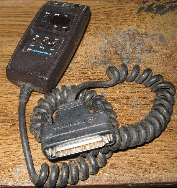
The HHCH plugs directly into the radio, or a special extension cord that has DB25
connectors on each end.
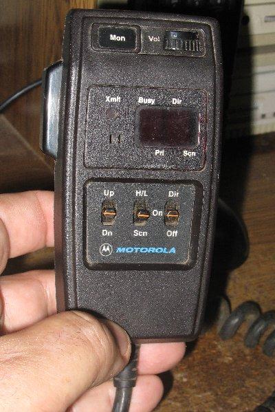
There is no channel name (or channel label) display - just a two digit display (which
limits A3 radios to 99 modes). The equivalent mike for the Astro Spectra has a
two-line LCD display (photo).
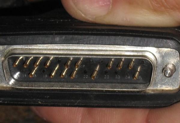
The DB25 does not have all the pins.
The biggest problem is that spare parts / repair parts (especially the switches and
the volume control) are no longer available. The channel up/down switch usually is
the first to go and later problems include that the insulation on the special curly
cord flakes off in big chunks. The A3 head is the rarest of the heads.
|
Here's a montage photo of an Astro Spectra W3 Hand-Held
Control Head (HHCH). As you can see, it gives the user a lot more functionality,
much like a normal control head on a dash-mount radio.
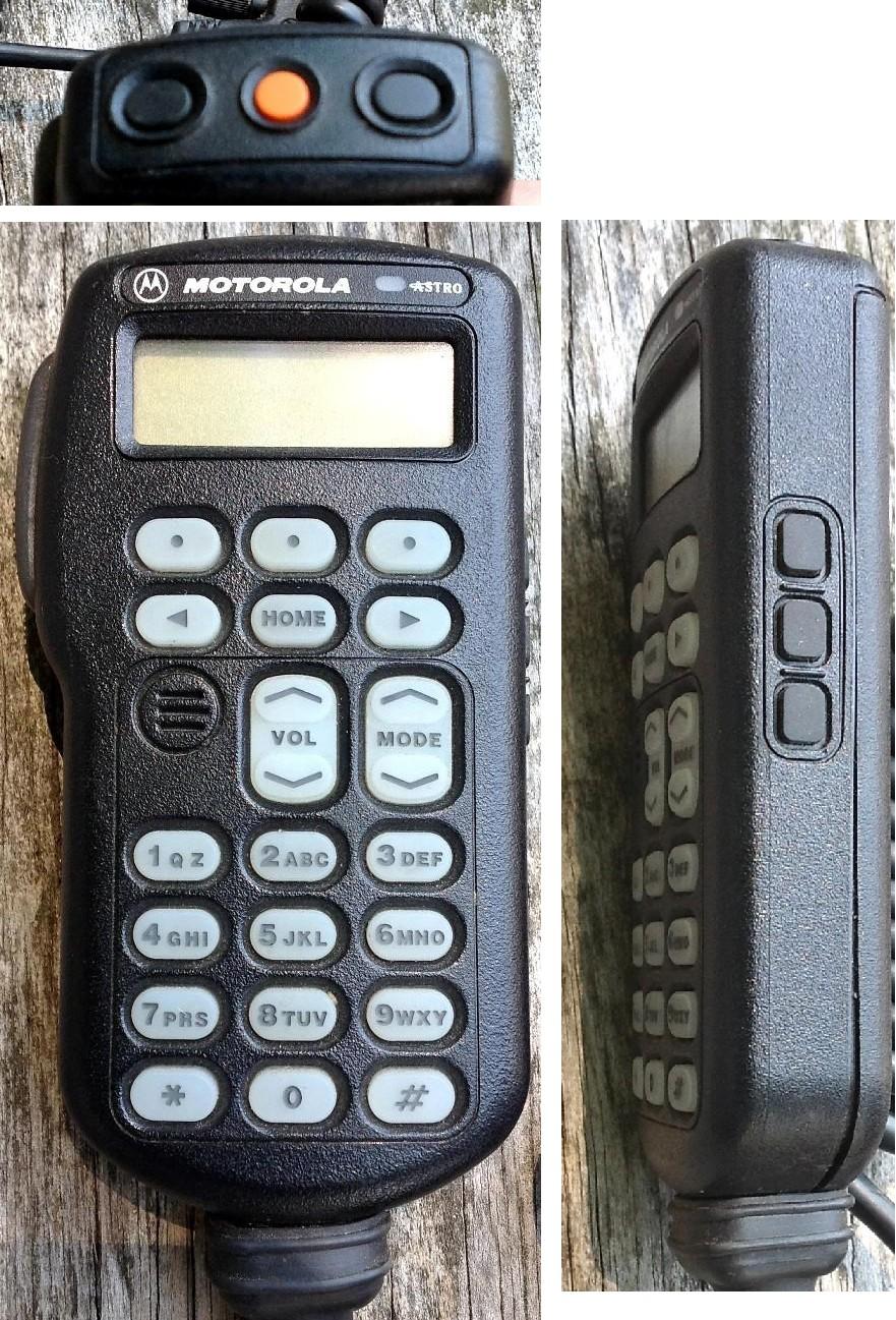
The HHCH plugs directly into the control jack on the front of the radio, or an
extension cable that has DB25 connectors on each end.
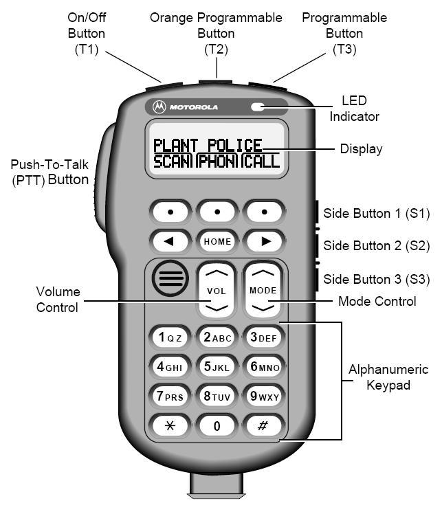
This page from the service manual details all the buttons.
|
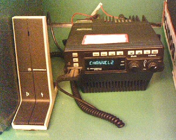
An A4 base station on top (the left knob is Mode, the right knob is Volume)
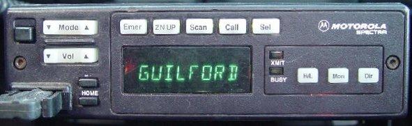
An A5 mobile
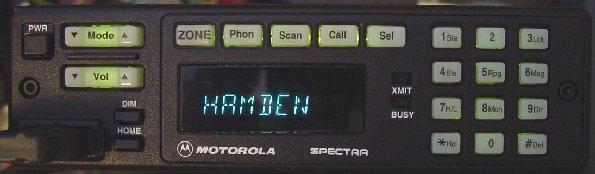
An A7 mobile
All of the above have 8 characters in the display.
And yes, the A4 and A5 also light up at night (that photo was taken in the daylight).
|
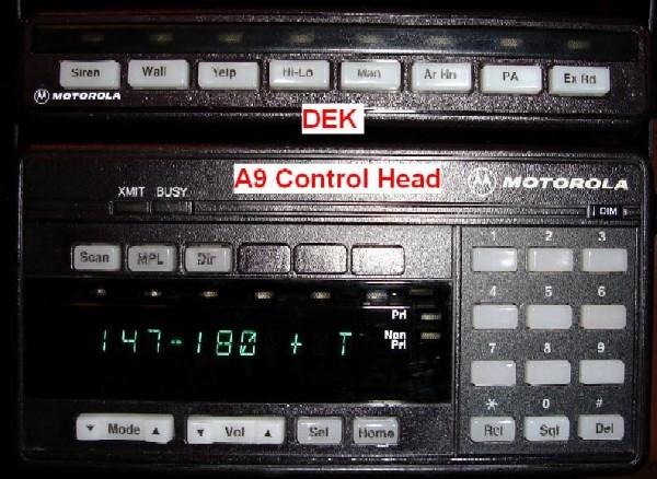
A DEK on top of a A9 head. These heads have 11 characters in the display.
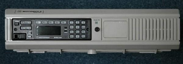
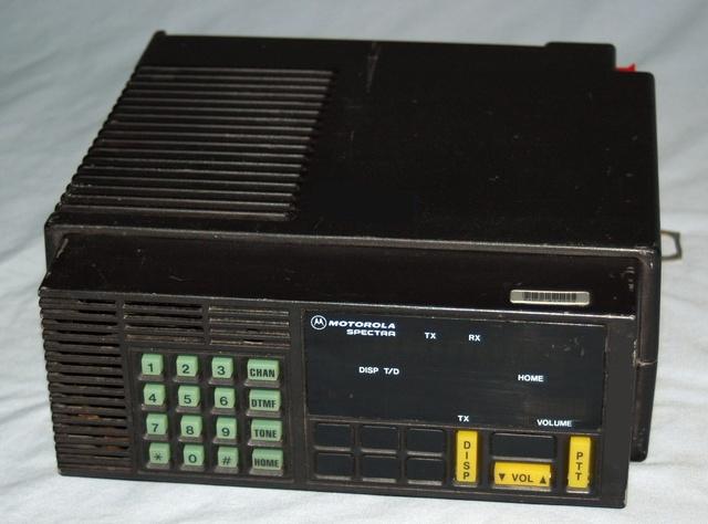
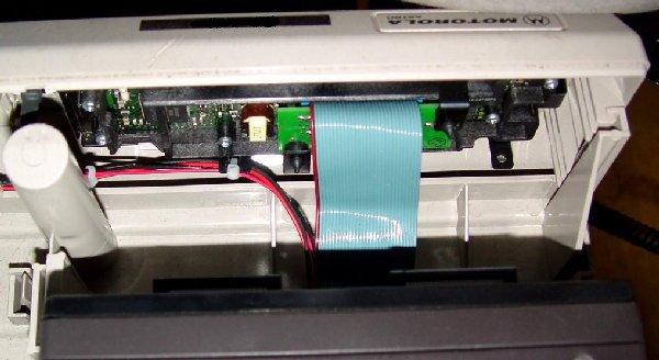
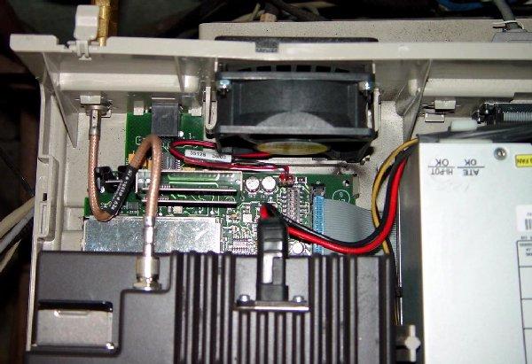
An A7 Spectra desktop base station (without microphone)
These units have an internal power supply, and there are UHF repeater versions
with two radio chassis and a mobile duplexer inside. However as a repeater they
have the normal mobile limitations on transmit duty cycle. The photo of this
particular one was taken with it sitting vertically on the back of the cabinet. The
black dot under the "Power On" light is the secure keyloader (i.e. encryption)
connector on encrypted base stations or the programming switch on desktop repeaters.
The white square knockout to the right of center is for the clock option. Motorola
also refers to sets with Astro radios as Consolettes. A similar version containing
one or two MaxTracs would be called a DeskTrac. Internal photos of a similar unit
show what looks like a PC power supply, a fan, an interface board (tone remote
control or analog wire-line), and an Astro Spectra remote mount mobile radio. Click
on the links below for more photos.
Top view
Rear view of the control panel
Rear of the radio showing the antenna jumper and
the wireline control board
You should read the Spectra Desktop Station article at the end of this page for
more detailed information.
|
An A7 Spectra tabletop base station - speaker-box-under-a-mobile type
(with mobile microphone) These units use an external power supply that is larger than a
red clay brick.
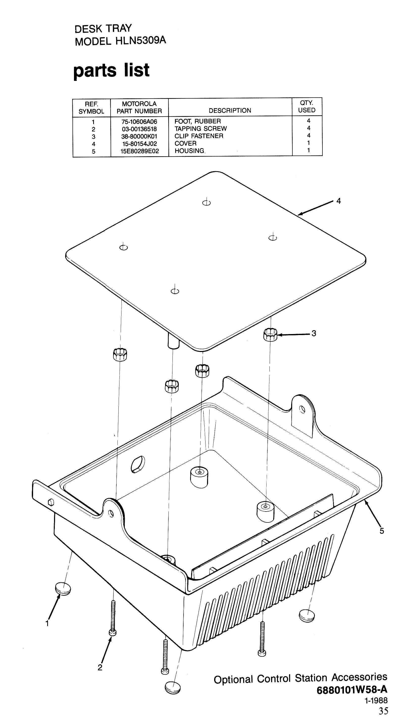
The Spectra desktop base tray is the HLN5309 or HLN6042A, both of which contain a
speaker, whereas the MaxTrac and GM300 use the HLN5292B tray - it's identical except
that it is missing the speaker.
The Spectra version parts list
is here.
|
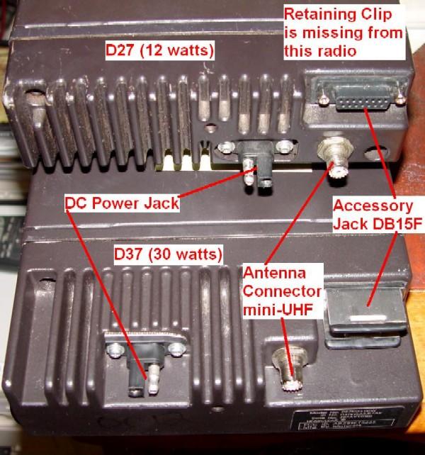
| The photo shows two 900 MHz radios. The joint between the heatsink and radio
chassis is easily seen. The 30 watt heatsink is longer and the connectors are
oriented on the top of the heatsink rather than on the back, as they are on the
low power heatsink. The difference in the front-to-back size (the depth of the
radio) really isn't more than 2 inches, if that. See the "Programming cable"
article in the Spectra section for more information on the accessory jack. On
the power connector, the exposed pin on the radio is positive (it's insulated
on the power cable). |
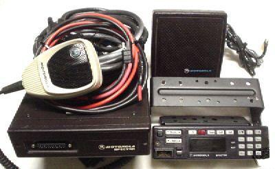
| This photo shows a complete low-power / mid-power mobile radio
kit, with control head, a mounting bracket, a coiled up control and power
cable kit, microphone, speaker, and control head. This particular kit has an
A7 head (the full keypad on the right side of the head). |
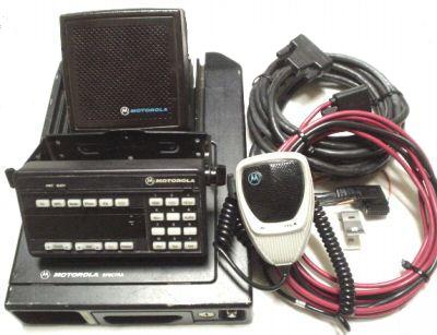
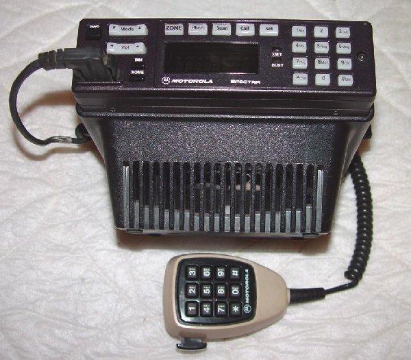
| This photo shows a complete high power remote mount mobile radio kit,
with a control head, a head mounting bracket, coiled up control and power
cables, mike and speaker. Not visible is the radio tray that is bolted to
the vehicle. This particular kit has an A9 head. |
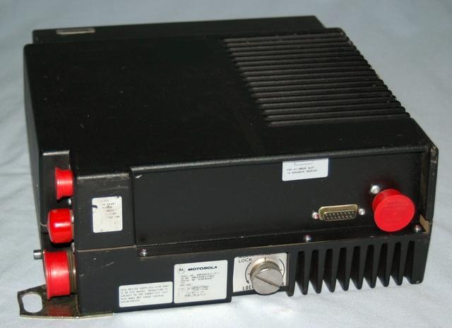
A rather interesting Spectra. This is what is used in railroad locomotive cabs. There is
no mobile microphone jack, the engineer uses a handset plugged into the round connector
on the right rear. The SO-239 antenna connector is under the cover on the top left connector
in the photo of the rear of the radio. The big red cap at the bottom left is the DC power
input connector, and has multiple pins. Specific wiring of the mating connector selects 12vDC
negative ground, 36 or 72vDC, floating ground operation; there is no voltage select switch
to set improperly. Most modern locomotives are 72vDC, the 12vDC mode is used in automobiles,
pickup trucks or on the repair bench. This particular radio is a MBR43KME1170AD. The
leading MB indicates Canadian manufacture, the R in the R43KME indicates Railroad.
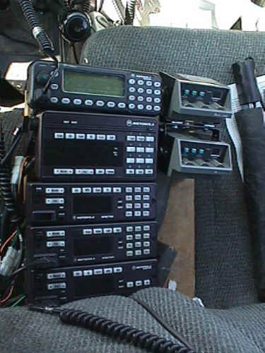
| K6CCC's truck control group (looking down at the console from head height)... From the
top is a MCS2000 on 900 MHz (the shop radio), a Syntor X9000 on 800 MHz (using a type 9 head),
three Spectras on 482-512 MHz, 450-482 MHz (both with type 7 heads), and a 146-174 MHz on a
type 5 head. To the right are a pair of Midland Syntechs on low band. The Syntor, Spectras
and Midlands are used for state and local gov't, law enforcement and fire communications.
Amateur radio communications utilize a few frequencies in the high band Spectra plus an
overhead-mounted Kenwood 742 on 220 MHz, 440 MHz and 1200 MHz. The truck in the photo is a
1986 Toyota pickup that was recently retired after 300,000 miles. The radios are going
into a new truck. |
FAQs not answered / handled:
1) How to use the wrong head on a radio (i.e. using an A5 head on an A4 radio, or an A4
head on an A7 radio, etc). Also, how to straighten out a mismatch (This is a candidate for
a bit banging article on how to change the control head type, from what I've been told it
just requires changing the model number in the MLM and the Command board in two different
memory locations and you're all set).
2)How to crack the model number / ID number... Full, current model number information doesn't
seem to be available. There is a partial chart below that has been reverse engineered. Some
spectras have both an "ID Number" and a new format "Model Number" in the format of
"TA9KX-068W" and nobody seems ot have a breakdown chart on that format number.
3) There is an early Spectra and a later Spectra II, commonly called the "E-Series".
Apparently the latter gives SmartZone capability for trunking systems and uses a
different command board which does NOT have a separate MLM (memory logic module).
Mike Blenderman K7IC has a
very extensive web site on Spectras, and there is no point in duplicating his effort
here at Repeater-Builder. This web page is only going to cover topics that are
not covered at Mike's site.
I really suggest that you go to
Mike's site first (and
bookmark it) as the topics there include:
- Model number breakdown - for example, the 9th character of model number is the radio type:
A=Conventional,
B=Privacy Plus trunking,
C=SmartNet trunking,
D=StarSite,
E=Enhanced.
The primary difference between the A, B, and C series heads is the legends on some of
the buttons; some are useful only for trunking.
- Manuals (both Basic and Detailed Service Manuals plus RSS manuals) - including which
manual part numbers are the good ones to order
- Single Radio Drawer Mobile Configurations
- Control Heads (including the Hand Held Control Heads)
- Remote Mount / Trunk Mount Configurations
- Programming Tips
- Systems 9000
- Cables (both vehicle and motorcycle)
- Accessory Cable Pin Out
- Direct Entry Keyboards / DEKs - a fancy name for a box with pushbutton switches on
it, that is used in conjunction with a X-9000 or Spectra radio. The buttons can be
programmed to do many things, like activate various siren modes, send status information,
or send specific messages, either via MDC1200 or trunking data. DEKs only work with a
remote mount control head that has a Systems 9000 VIP (Vehicle Interface Port) connector,
which with the Spectra usually limits you to a A9 head (the large one). The code plug must
also allow the DEK to work (i.e. enabled in RSS). If you have an A4, A5 or A7 type then it
may not work with a DEK. The maximum number of DEKs can be attached to the radio is three.
They use the serial communications bus on the accessory jack and multiple units just
daisy-chain together. The buttons and status value or message text are programmed via RSS
in the control head section. Not all radios support DEKs. The DEK is a appliance for the
control head and will not substitute for it. A DEK is only a very simple hardware interface
that takes parallel pins and translates them to a primitive synchronous serial data stream
the control head can use. All the other stuff like status messages and such is all in the
RSS / code plug software. There is no way to "program" something as simple as the
DEK hardware itself.
- Parts and Accessories
- Spectra Radio Circuit Boards
- Remote Mount Kits
- Accessories
- Parts for Control Heads, DEKs and Speakers
- DPL / DCS Information
- Surplus Parts Guide
From a ham's point of view, the A7 radio is probably the most desirable, as it's a
(usually) 128 channel conventional radio (i.e. not trunked) and has the 12-button
8-character display control panel / control head. The A5 is the second choice,
the A4 has the volume and mode knobs. If you are going to use a remote mount radio (i.e.
the radio chassis is in the trunk), and have the dash space, then the A9 control head may
interest you as it has 3 more characters on the head display plus you can use a DEK.
Radios equipped with a type 7 and type 9 heads will generate 12-button DTMF, there
never was a 16-button DTMF model made (to be precise, the command board generates the
DTMF, but unless you have the right head it won't work). If you need 16-button DTMF
then use a Motorola touchtone microphone and modify it as per the Jim Reese WD5IYT
article (on the Motorola index page), or use a Midland or Johnson 16-button microphone
and modify it for the Motorola microphone circuitry (and with a Spectra microphone
cable and plug).
The Moto TouchTone / TouchCode / DTMF microphones have a different model number
to cover every seemingly different combination of non-backlit or backlit, trunking
or conventional, and every mobile radio connector from the 1950s Motrac on up.
All are covered in the Motorola Touch-Code Encoder Microphone instruction manual
6881114E07, which as of this writing (mid 2009) is still available from Motorola
Parts for less than US$3. That's right, less than $3. The model tables in the
manual mention fifteen different DTMF mikes, including the HMN1053A (which is
the standard DTMF mike for a Spectra mobile radio).
Spectra Model Chart (partial)
| Sample model number: D44ZXA5JC7AK |
| D |
4 |
4 |
Z |
X |
A |
| Mount Type |
Power Level |
Band Split |
Unknown |
System Operation |
Supply Voltage |
| D Dash |
1 <10 W |
1 Low Band VHF |
F ? |
G Trunking |
A 12v [1] |
| L Consolette |
2 15 W |
2 Mid Band VHF |
K ? |
M Conventional |
|
| M Motorcycle |
3 30 W |
3 High Band VHF |
V ? |
X SecureNet |
| T Trunk |
4 50 W |
4 UHF |
Z ? |
|
| Z Special |
6 75 W |
5 800 MHz |
|
| |
7 100 W |
7 900 MHz |
| 8 110 W |
If anyone has the breakdown of the fourth column ("Unknown"
in the table above), we'd appreciate the information.
| 5 |
J |
C |
7 |
A |
K |
| Operational Mode |
Model Specific |
Control Version |
Control Type |
Version |
Package |
| 5 Trunking |
J Model Specific |
A Conventional |
2 Limited (rare) |
A |
K [4] |
| 7 Conventional |
|
B Privacy Plus |
3 HHCH [2] |
B |
H [5] |
| |
C SmartNet |
4 Rotary |
C |
N [6] |
| D StarSite |
5 Standard (3 Button) |
D |
|
| E Note [3] |
7 Expanded (12 Button) |
E |
| |
8 Expanded Control Station |
|
| 9 Systems 9000 |
|
[1] Negative ground.
[2] HHCH = Hand Held Control Head.
[3] Enhanced or SmartZone, depending on which book you read.
[4] Shipped with the standard mobile installation kit.
[5] Shipped with the standard mobile installation kit except that the
microphone and hangup clip are replaced with a handset and a handset hangup cup (common
on railroad radios, transit busses, subway cars, and mountain cable cars).
[6] Warranty replacement - Shipped with no accessories (just a radio in a
plastic bag in a padded cardboard box).
The following table was extracted from the Feature Matrixes in the Spectra 900/9000
Basic Service Manual, 6880101W37-C, for 4, 12, and 30 watt, 900 MHz mobile radios.
Entries in the table with no revision letter came from the matrixes in the front of the
manual. Entries with a revision letter (A, B, C, D, or E) came from an appendix that
has additional feature matrixes based on the 11th character of the radio's model number.
The 12th (last) character is always 'K' in these charts.
In the table below:
- "Head" column is the 9th and 10th characters in the 12-character model number
(the "Control Version" and "Control Type" columns in the above table).
- "Rev." is the 11th character in the 12-character model number. A "#" indicates
no revision letter.
- "Conv." is the number of conventional channels or modes.
- "Sys." is the number of trunking systems.
- "Flt." is the number of trunking sub-fleets per system.
| Head |
Rev. |
Conv. |
Sys. |
Flt. |
| A5 |
# |
128 |
0 |
0 |
| A5 |
A, B, C |
32 |
0 |
0 |
| A7 |
# |
128 |
0 |
0 |
| A7 |
A, B, C |
64 |
0 |
0 |
| A9 |
# |
128 |
0 |
0 |
| B2 |
#, A, B |
0 |
2 |
2 |
| B5 |
# |
10 |
10 |
10 |
| B5 |
A, B |
0 |
3 |
8 |
| B5 |
C, D |
1 |
6 |
8 |
| B5 |
E |
10 |
10 |
10 |
| B5 |
F |
128 |
10 |
10 |
| B7 |
# |
10 |
15 |
10 |
| B7 |
A, B |
0 |
8 |
8 |
| B7 |
C, D |
10 |
8 |
8 |
| B7 |
E |
10 |
15 |
10 |
| B9 |
# |
10 |
15 |
15 |
| B9 |
A, B, C, D |
10 |
8 |
8 |
| B9 |
E |
10 |
15 |
10 |
| C2 |
#, A, B, C |
10 |
8 |
8 |
| C5 |
#, A, B, C |
10 |
8 |
8 |
| C7 |
# |
10 |
15 |
16 |
| C9 |
# |
10 |
15 |
16 |
The 9th character specifies the trunking/coding style:
- Ax radios are conventional only.
- Bx radios are Privacy-Plus.
- Cx radios are SmartNet.
- Ex radios are SmartZone.
The 10th character specifies the type of control head. All of these control heads have
rocker buttons for MODE and VOLUME and an 8-character 14-segment display unless otherwise noted:
- An x2 head is an x5 head with fewer buttons above or to the right of the display.
- An x5 head has only 3 buttons to the right of the display.
- An x7 head has 12 buttons to the right of the display and can do DTMF.
- An x9 head (System 9000) has 12 buttons, an 11-character display, and can do DTMF.
An E7 radio was capable of 10 conventional modes and 15 systems of 16 sub-fleets each.
After deleting all but the last trunking system and its modes, I was able to increase the
number of conventional modes to 128, but I didn't try filling them all.
There's only so much codeplug space in the radio; each trunking system reserves space
for all of its sub-fleets, whether they're utilized or not. You can increase the conventional
mode space by giving up some trunking mode space, on those radios that support both.
Spectra and Astro Spectra compatible microphones:
The A9 / W9 / Series 9000 head, has its microphone jack on the rear of
the control head. It's still a six-pin connector, but it is oriented vertically rather than
horizontally. All of the Spectra microphones plug into either front or rear connectors.
All of the mobile microphones are hand-size; there are no palm-size microphones (such as
the HMN1056D that's common with MaxTracs; see the comparison photo in the Motorola section
of this web site).
The microphone connector on the a Spectra microphone has 6 pins and looks like:
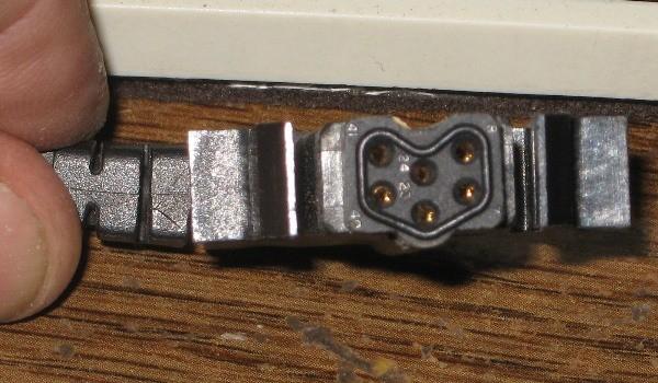
The pattern of the 6 pins is the same as in a DB50 plug.
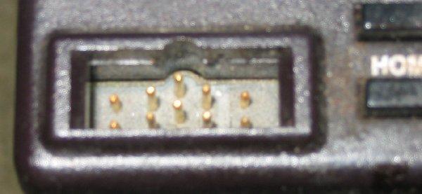
...but the mic connector on the front of the radio has 10 pins...
The outer 4 are used for, among other things, the encryption keyloader.
Does anyone have the part number for the keyloader cable or plug that mates
with all of the pins in the mic connector?
A list of known Spectra-compatible mikes is shown below. If anybody knows
of others or wants to contribute schematic scans, let Repeater-Builder know.
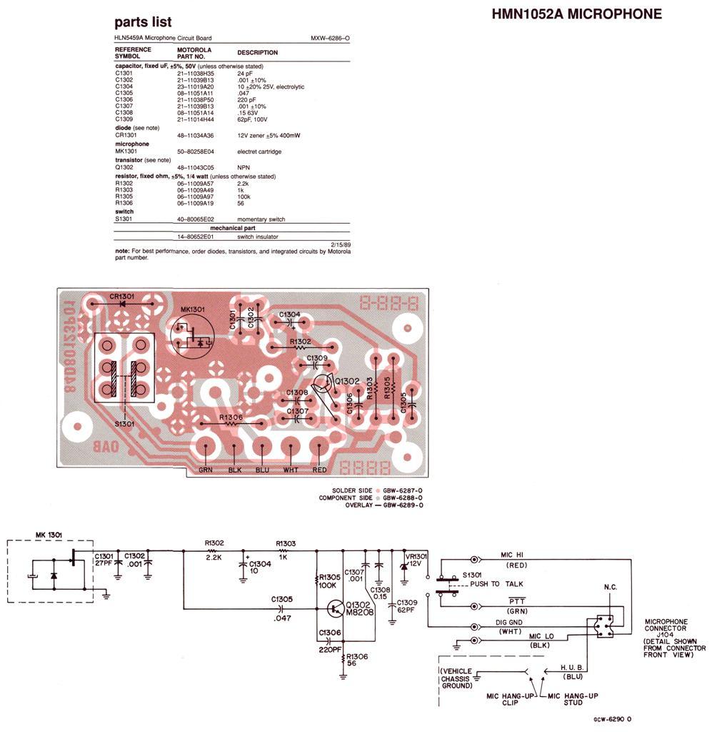
- Standard microphone HMN1052A; a schematic
and circuit board layout can be found here. This mike is specified for the
MaraTrac radio but it has a Spectra connector at the end of the cable.
- Standard microphone HMN1080A (replaces HMN1052A now NLA)
- Standard microphone HMN1061A used on Systems 9000 / A9 head
- DTMF microphone HMN1032B
- DTMF microphone HMN1053A (supposedly this one won't work on an Astro Digital
Spectra, I don't know why, or if this statement is even correct)
- Noise Cancelling microphone 5084898K10 (also available as HMN4030A)
- Handset (with hangup box) HMN1079B
- Water resistant microphone HMN1079A
- Motorcycle Weatherproof Microphone HMN1062A (usually paired with the HSN6003
weatherproof speaker)
- Desk-top microphone HMN1050A, B, C or D (this microphone has both the PL defeat
and PTT buttons)
Some of the motorcycle microphones, such as the HMN1079A had a DE-9 male connector on them.
DC Power:
Spectra Mobile Power Consumption:
| Model Series |
Standby |
Receive |
Transmit |
| D43 (High Band 25-50w) |
0.45A |
2.5A |
13.0A |
| T83 (High Band 110w) |
0.45A |
2.5A |
27A |
| D14 (UHF 4w) |
0.5A |
2.5A |
3.5A |
| D34 (UHF 25w) |
0.5A |
2.5A |
6.5A |
| D44 (UHF 40w) |
0.5A |
2.5A |
12.5A |
| T84 (UHF 100w) |
0.5A |
2.5A |
31A |
| D45 (800 MHz 35w) |
0.5A |
2.5A |
13.5A |
| D17 (900 MHz 4w) |
0.5A |
2.5A |
4.5A |
| D27 (900 MHz 12w) |
0.5A |
2.5A |
7.0A |
| D37 (900 MHz 30w) |
0.5A |
2.5A |
13.5A |
|
NOTES: "Standby" implies receiver squelched. "Receive" is the power
consumption at maximum volume setting and with white noise. All of these are MAXIMUM
current values taken from Motorola manuals; most radios draw considerably less.
With the System 9000 control head, all the current drains increase by 0.2A due to the
additional segments on the display and additional computer components.
The radios will draw about 0.4A when first connected, but this will drop to about
25mA after a couple of seconds, but ONLY if the radio is turned off and you have the
Emergency Input line grounded inside the Accessory plug. If you don't, the radio will
continue to draw 0.4A. The Ignition input draws about 1 mA all by itself.
Spectras will not turn on without 12 volts present on the Ignition Control line.
Applying just main radio power without a properly configured Accessory plug installed
is not recommended.
The DC power input is protected from reverse polarity by a large diode that is reverse
biased in normal operation. This diode is mounted on the PA board near where the DC power
comes in. If power is applied with revrse polarity the diode will conduct and will blow
the fuse. You did fuse your battery (or power supply feed), right?
Other Notes:
Splits / Ranges
Spectra's come in several frequency bandsplits, called Ranges. You cannot tell the range of the radio just by looking at the model
number, you will have to read the radio with the programming software (RSS) in order to determine what frequency range it covers.
Below is a list of the available ranges for VHF and UHF.
- VHF Range 1: 136-162 MHz (rare)
- VHF Range 2: 146-174 MHz (common)
- UHF Range 1: 403-433 MHz - FCC ID AZ492FT4779 (rare)
- UHF Range 2: 438-470 MHz - FCC ID AZ492FT4776 (common)
- UHF Range 3: 450-482 MHz - FCC ID AZ492FT4777 (common)
- UHF Range 4: 482-512 MHz - FCC ID AZ492FT4778 (rare)
After The FCC made the some of the UHF TV channels (14: 470-476 MHz (the so-called
"T" or "Top" band), 15: 476-482 MHz, 16: 482-488 MHz,
17: 488-494 MHz, 18: 494-500 MHz, 19: 500-506 MHz, 20: 506-512 MHz)
frequencies available to Public Safety operations (i.e. police, sheriffs, etc.) Moto Engineering came up
with the Range 4 radios.
After Moto sales got a bunch of Request For Quotes (RFQs) for
radios that would cover both 460 and 482 MHz channels. Moto Engineering came
up with the so-called "Range 3-and-a-half" model that cover 453-488 MHz.
In order to determine the range of any particular radio you will have
to do one of two things:
1) Read the radio with RSS (which may not work, see below)
2) Open it up and look at the part numbers on the RF modules.
Using a frequency counter to tell where it's transmitting will do no good. For example, if
it was transmitting on 157 MHz (actually anywhere from 146 to 162 MHz) you could
not know which of the two VHF ranges it was in without opening up the radio and looking at
the part numbers on the modules. And it could have had a wrong range code plug stuffed into
it or been programmed with a modified RSS... several eBay sellers have been discovered selling
403-433 MHz range radios with a 460 MHz range code plug programmed into it, and
136-162 MHz radios with a 146-174 MHz code plug.
Note: The page author and maintainers would love to find a 136-162 MHz Spectra or Astro-Spectra radio.
In short, the only way to really tell is to look inside and read the module numbers - or
look the FCC number up on the above list (and pray that the receiver front end matches
the PA deck (where the sticker is)).
There never was a low band Spectra. The nearest to it is the trunk-mount
low band Syntor X9000 and I have it on good authority that only 1,500 of those
were ever made. They are in demand by emergency responders as they will do
30-50 MHz (actually 25-54 MHz) in one range, and when coupled
to an autotuning screwdriver antenna can do drastic changes in frequency (like
switching from a 33 MHz Air Force SAR channel to the Red Cross
47.42 MHz nationwide frequency to a 39/43 MHz California Highway
Patrol repeater pair), and doing it all while in motion on the highway.
Very few high power remote mount / trunk mount Spectras were made in UHF
Range 2 - that particular factory configuration is a good example of pure
unobtanium... Several have been field assembled (and sold to unsuspecting hams)
by taking a front end and exciter from a dead Range 2 438-470 MHz
front mount radio (there were a lot of motorcycle radios made in Range 2)
and installing it into a Range 3 450-482 MHz trunk mount radio, and
then telling the radio it's a Range 2 but the transmitter performance may drop off
drastically as you head towards 440-445 MHz (there are some modifications
that can be made to the transmitter but they are not simple).
All the high power radios are remote mount / trunk mount only.
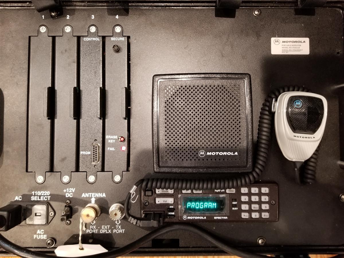
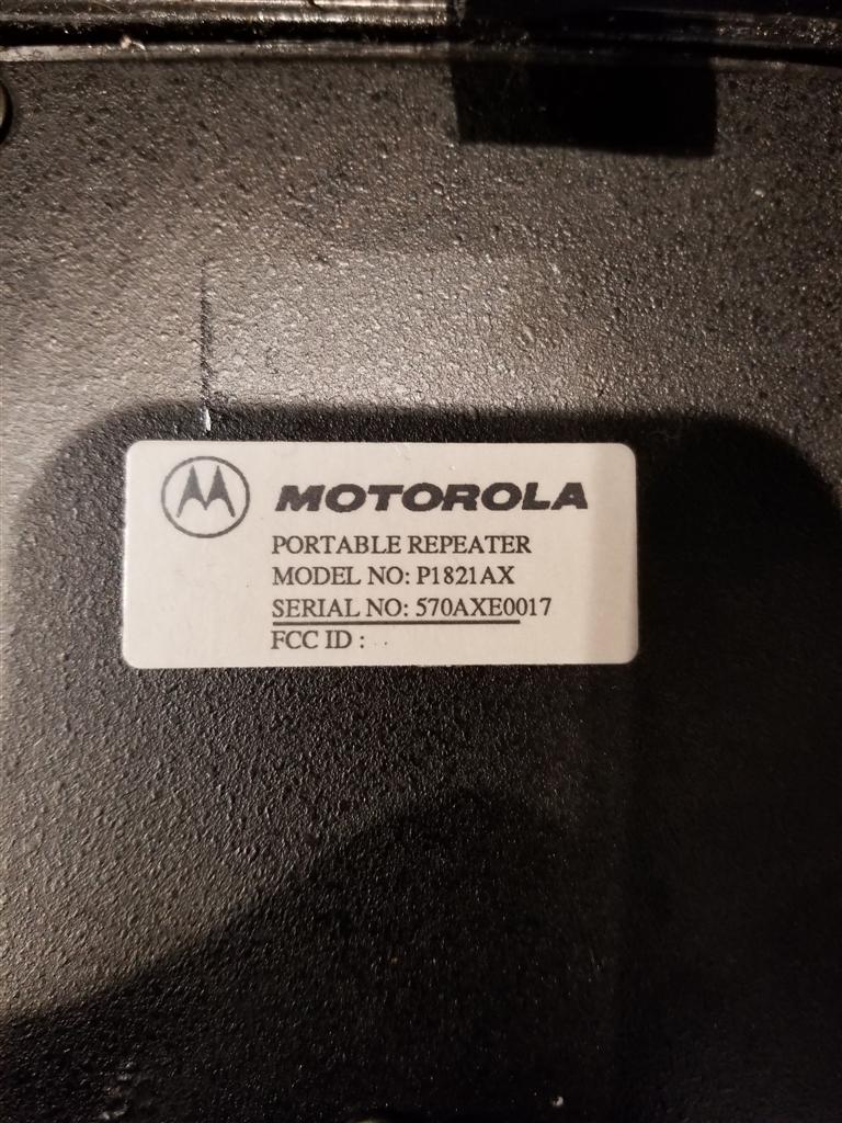
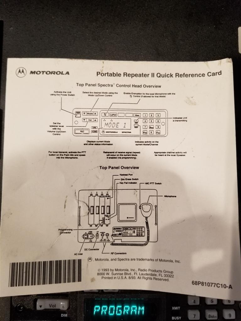
Suitcase Repeater
There was a portable repeater based on Spectra mobile radios, often known as
a "suitcase repeater". The manufacturer of the outer aluminum case was Zero
Manufacturing of Burbank, California. Michael N2WGC sent some photos of one.
Click on the links below.
Programming
If RSS or the RIB is a new topic to you I suggest that you see the RSS and RIB pages at this web site.
Spectra and Astro-Spectra radios were in production when the average PC was a 386 or 486 and
had a real hardware serial COM port (either 25-pin or 9 pin).
Spectra radios are programmed with RVN4001. The last Revision was R06.00.05, RVN4001N.
It was supplied on 3.5 inch floppies and must be run under MS-DOS (DOS 6.22 was current then).
If I'm remembering correctly it is limited to COM1 or COM2. The RSS manual was 6880101W48.
Anyone have a paper copy we can scan?
Astro-Spectra radios are programmed with RVN4183. The last Revision was R05.03 in 2008
and will run under XP or 32-bit windows 7. It is limited to COM1 to COM4.
Anyone know what the RSS manual number was? Anyone have a paper copy we can scan?
Original Astro CPS will launch/run on both 32 bit and 64 bit Windows but it will
only physically talk to the radio on 32 bit. Astro Tuner lets you select higher Com ports but
only actually works on COM1-4. You need 32-bit XP or 7, and generally a REAL (hardware)
RS-232 serial port. There are a few USB adapters that will work, but most won't.
Programming 2 meter and 440 MHz amateur frequencies is no problem as
VHF range 1 covers 2 meters and UHF range 2 covers 440 MHz. However to
program 900 MHz amateur frequencies into the radio you will have to hex-edit
one file in the RSS package: "spectra1.exe". Instructions are available in an article
in the Spectra section. Also the VCO might need to be modified slightly (definitely
necessary for 900 MHz radios - see the article in the Spectra section).
If you plug a programming cable into a Spectra, and the RIB is attached but not
powered up, the radio can do all sorts of strange things like turn on and off and
display some error codes. You'll think you have some bad connections. The RIB loads
down the BUSY and BUS lines and confuses the radio. The solution is to apply power
to the RIB before attaching it to the radio. The Spectra has a switched +12vDC pin
in the accessory / programming connector that (among other things) was
intended for powering the real Motorola RIB (RLN4008 series) through the
programming cable (to pin 12 of the DB25F connector on the RIB).
Speakers
The standard HSN4018B speaker is 8 ohms. An optional HSN6001A 3.2 ohm speaker
was available that is louder than the standard speaker. Never ground either radio speaker
lead. Grounding any/either speaker lead will destroy the audio amplifier chip on the
Command Board and those chips are no longer available. Motorola sells an SLN6435A
audio isolation transformer for connecting test equipment, like a SINAD meter, to the
radio speaker leads. Being "Test Equipment", it costs lots, but any transformer with
an 8 ohm winding and another winding from 8 ohms to 2K ohms will allow your
test equipment to work.
Mounting Bracket
The Moto part number HLN5015 is the dash-mount mobile mounting kit, containing the
bracket, some loose hardware, the power cable, with fuse holder and speaker connection.
Part number 0780086N01 is the bracket only (and the same bracket is used for the
control head in a remote-mount radio).
Display Font
If you look at the A9 - DEK control head photo at the top of this web page, you may notice
that there is no decimal point character in the control head "font"... just uppercase
alphabetics, numerics, a space and these characters: < > ? / \ @ * ( ) - and
the + sign. You would really expect the decimal point / period character
to be there, since you would expect to be able to display frequencies (like "146.46"
or "449.000") but it's not. Bob WA1MIK took the time and programmed every keyboard
character into the RSS and loaded the strings into an A7 radio; there's no way to display
a decimal point on any Spectra head. If you program the keyboard decimal point into the
RSS it displays as a backslash. The nearest you can get to a decimal point is the "-"
(hyphen) or "=" (equals character), the latter shows up as an underscore. Or do without
and live with "146460", "146-460" or "449_000", "449000". Or use names for the channels
like it was intended: "Simplex1" and "Sunset3". Interesting enough the "[" character (the left
square bracket) can be used as a display segment test as it is translated into an "all
segments on" character.
The reason you can't get some characters is that each position of the display is formed
with 14 segments: one horizontally at the top and bottom, two horizontally in the middle,
one each vertically at the upper left, upper center, upper right, lower left, lower center,
and lower right, and four that go diagonally in an "X" pattern. There's just nothing there
for a decimal point or lower-case letters. Here's part of a page from a Kenwood TK-981
manual that shows the possible display characters. It's similar if not identical to the Spectra:
Converting a Dash Mount to a Remote Mount
To convert a dash mount radio to a remote / trunk mount you will need a
HH1446A, HH1447A or HLN6008A Remote Mount Field Retrofit Kit which
contains all the parts necessary. I have no idea what the differences are between
the three kits. Anyone wnat to contribute?
A detailed service manual covering most models of the conventional and
trunked Spectras is Motorola part number 6880102W61 at about $45.
The basic service manual for VHF Spectras is 6881070C95.
Neither is available from Motorola however you might find one at of the
auction sites or a PDF elsewhere on the web. If anyone does turn one up
please email a copy to the page maintainer and he will add it to this page.
Contact Information:
Mike Morris WA6ILQ can be contacted here.
Back to the top of the page
Up one level (Spectra index)
Up two levels (Moto index)
Back to Home
This page was created in and is (c) copyright 2005 and the date of last update.
This page was last updated on
The photos of the A5, A7, two 900 MHz PA decks and the speaker-box-under-a-mobile
photos are by Robert W. Meister WA1MIK and copyrighted by him.
The A9 / DEK head photo is by Scott Lichtsinn KBØNLY and copyrighted by him.
The photo of K6CCC's truck radios by Jim Walls K6CCC and used with permission.
Artistic layout and hand-coded HTML © Copyright 2005 and date of last update
by Mike Morris WA6ILQ.
Motorola®, Spectra, Astro Spectra and a lot of other terms
are registered trademarks/servicemarks of Motorola Inc.
This web page, this web site, the information presented in and on its pages and
in these modifications and conversions is © Copyrighted 1995 and (date of
last update) by Kevin Custer W3KKC and multiple originating authors. All Rights
Reserved, including that of paper and web publication elsewhere.
