Up two levels (Moto index)
Back to Home
Old and New Motorola
Spectra Mobile
Radio Circuit Boards
By Robert W. Meister WA1MIK

|
Up one level (Spectra index) Up two levels (Moto index) Back to Home |
Comparing and Identifying Old and New Motorola Spectra Mobile Radio Circuit Boards By Robert W. Meister WA1MIK |
|
A reader sent me some circuit boards from a very old (1987 date code) 900 MHz Spectra radio. I took photos for historical purposes and returned them, then took one of my own (1993 date code) 900 MHz radios apart and took photos of the same boards while still in the chassis. This article shows some of the differences in side-by-side comparisons.
I've only compared the RF and command boards in this article. I'm sure there are some differences in the remaining Spectra boards and those that operate on other bands.
In the tables below, asterisks (*) are after the items highlighted in the photos. Click on any image for a larger view.
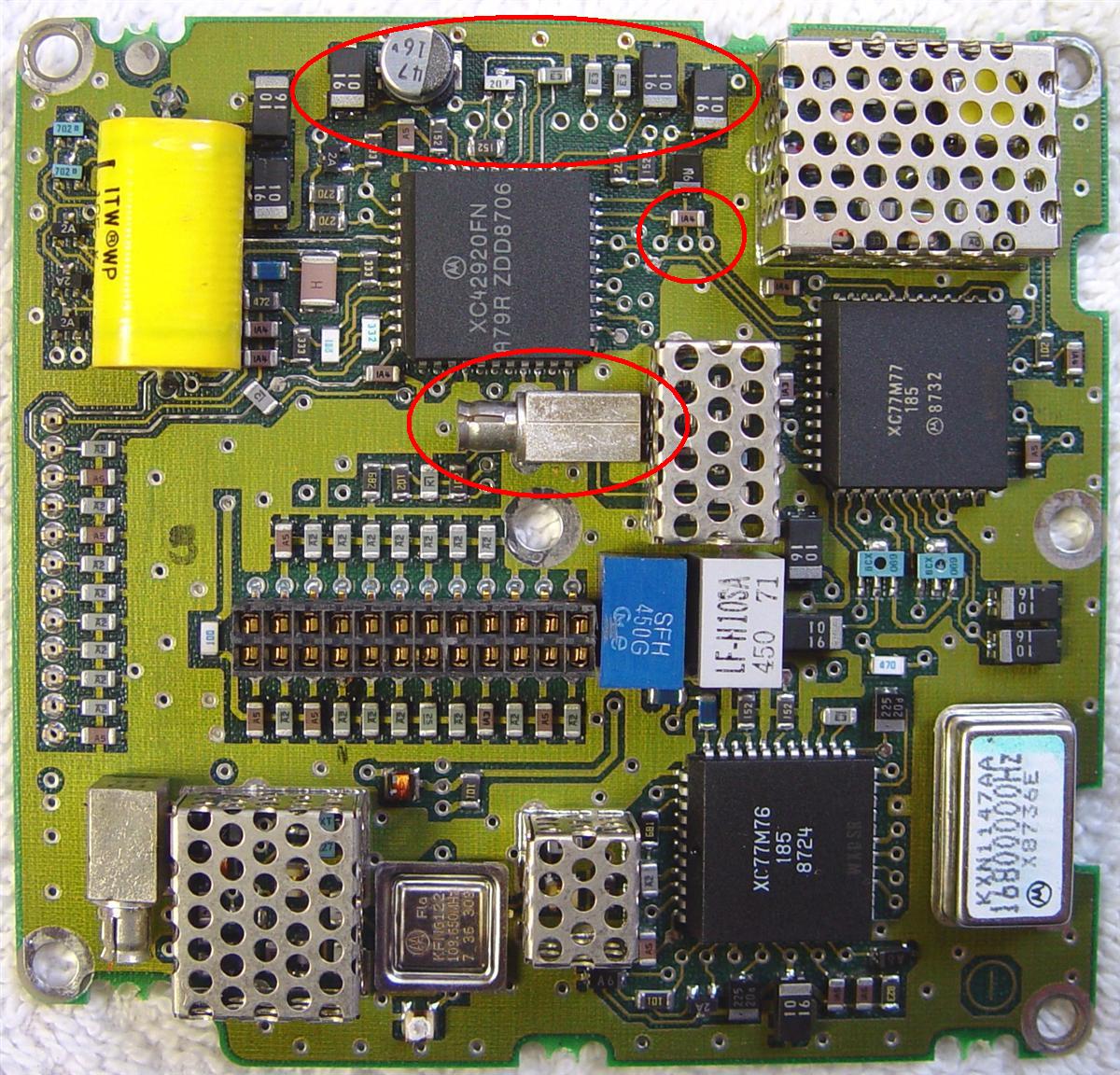
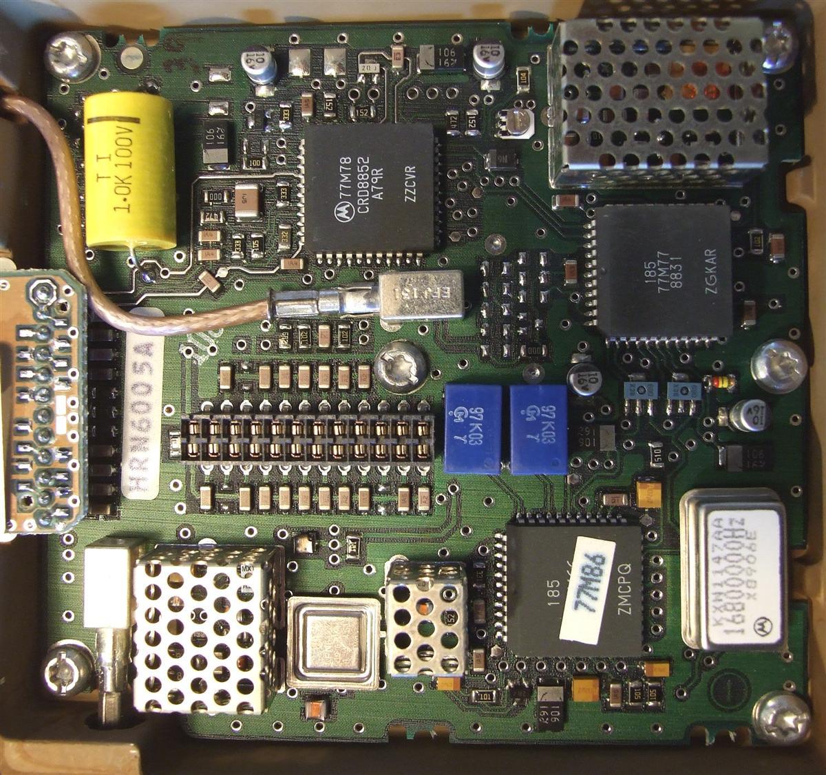
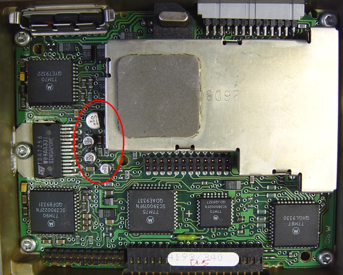
RF Board:
This board contains the reference oscillator (16.8 MHz in the lower right corner), the frequency synthesizer (the VCO is on a separate board that plugs into the RF board), the receiver IF circuits, filters, and demodulator, and the transmitter exciter buffer amplifiers.
| Old | New |
|---|---|
 |
 |
| Sticky label with HRN6001 underneath the board. | Sticky label with HRN6007B on top of the board. |
| No board "band" indicators. | LVU89 "band" indicators. * |
| One "time bomb" electrolytic capacitor; all others are tantalums. * | Four "time bomb" electrolytic capacitors; the big one is not used on 900 MHz. * |
| No 2nd oscillator potentiometer. | Has 2nd oscillator potentiometer. * |
| Has an extra SMB jack. * | No extra SMB jack. * |
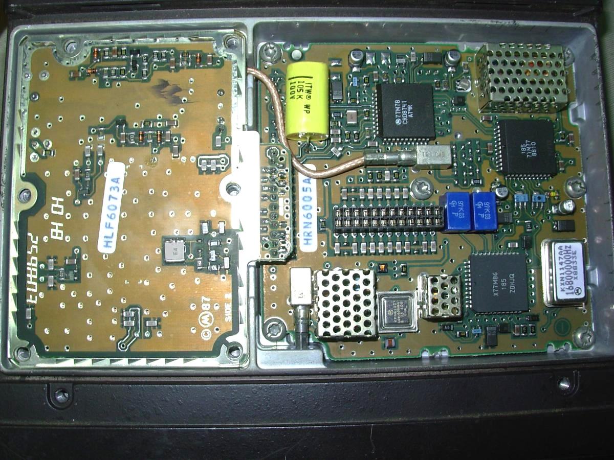
Keith WE6R sent me a photo of another old RF board (HLN6005A), this one on 900 MHz. There are a few less electrolytic capacitors than the new board, there is a 2nd oscillator potentiometer, and there is a coax cable inserted into that extra SMB jack.
Tim KF7EUO sent a photo of his 900 MHz radio showing the coax coming from the VCO. This seems to be feedback from the VCO to the synthesizer circuitry. Surprisingly, this jack is not depicted on the RF Board schematics.
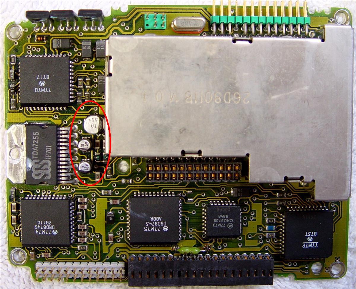
Command Board:
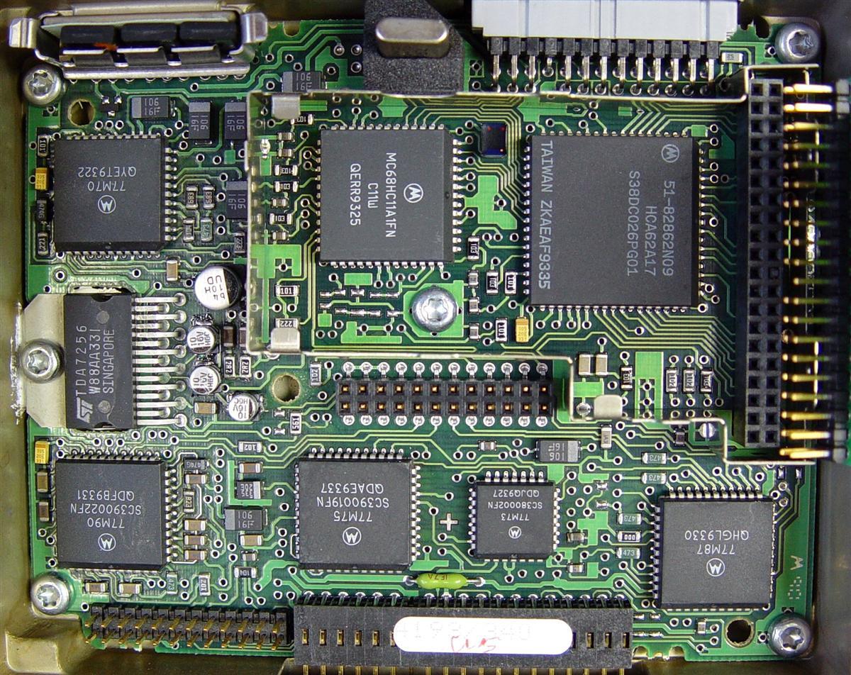
The command board contains the microprocessor, speaker power amplifier, transmit and receive audio processing (including PL/DPL encode and decode), transmit power control, and control head interface. A shield covers the Memory Logic Module (MLM).
| Old | New |
|---|---|
 |
 |
| TDA7255 audio PA chip. | TDA7256 audio PA chip. |
| Three "time bomb" electrolytic capacitors. * | Four "time bomb" electrolytic capacitors. * |
| Group of 5 pins to the left of the crystal along the top edge of the board. | Some other arrangement to the left of the crystal along the top edge of the board. |
| Sticker underneath marked HLN6024A. | No visible sticker, probably HLN6094B. |
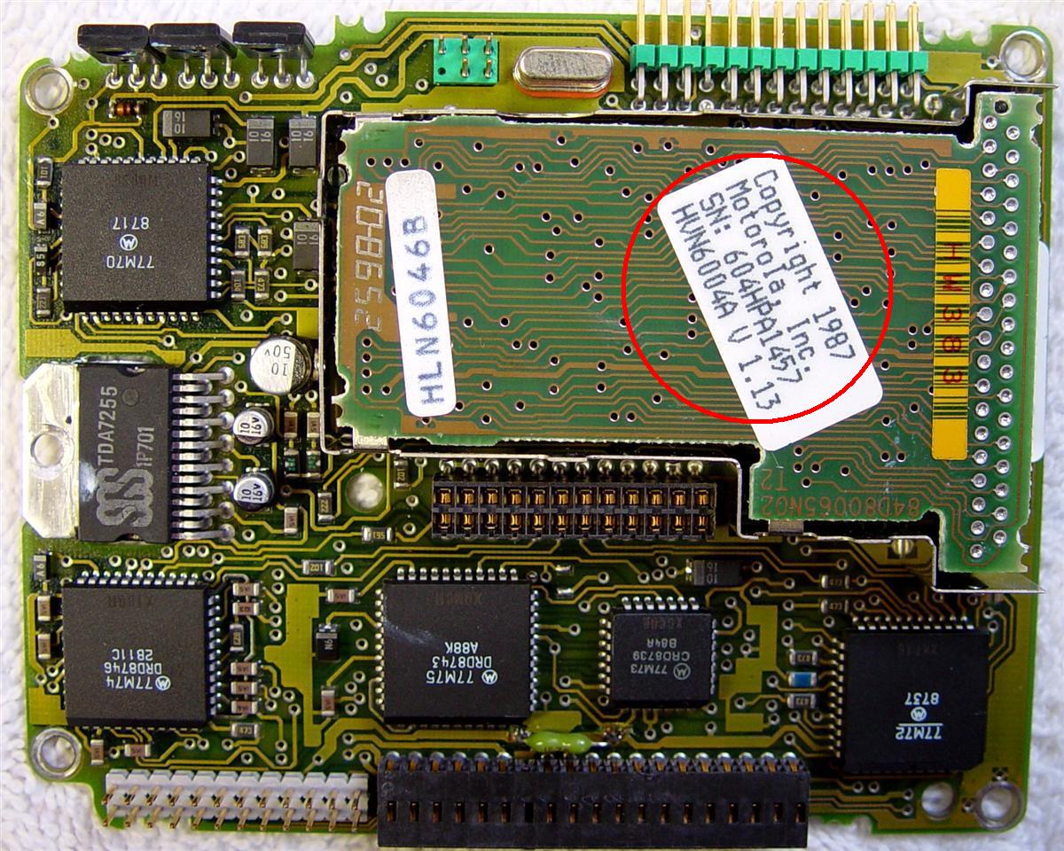
Memory Logic Module (MLM):
Removing the shield reveals the MLM, a small circuit board that contains the operating code for the radio in one or two ROM chips, one RAM chip for scratchpad memory, and one EEPROM for code plug storage. The radio's alignment parameters are stored in EEPROM within the microprocessor. Long (11 character) mode names are stored in the A9 control head. The two important pieces of data here are the serial number and the firmware version. The serial number in the MLM must match the serial number in the command board (set during board replacement procedures). There are also physical board part numbers and firmware product numbers.
| Old | New |
|---|---|
 |
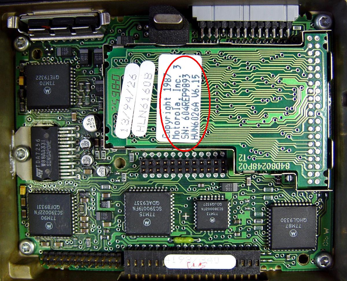 |
| S/N 604HPA1457, Version 1.13 * | S/N 604REP9893, Version 6.15 * |
| 37-pin staggered hinged connector | 40-pin two-row plug-in connector |
| Board P/N HLN6160B | Board P/N HLN6046B |
| Firmware P/N HVN6016A | Firmware P/N HVN6004A |
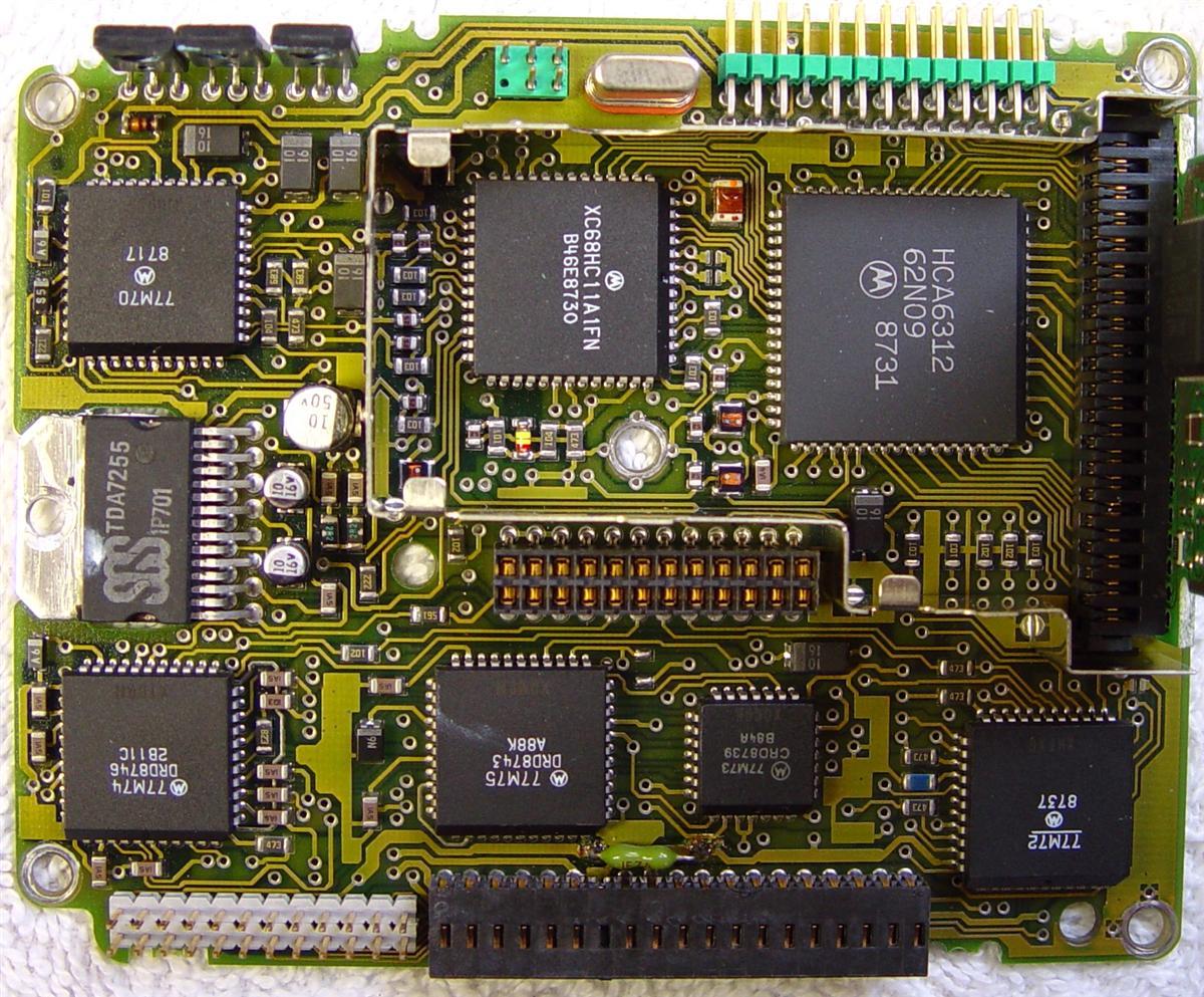
The old MLM is attached to the command board with a hinged connector at the right side. The left side lifts up. The new MLM has square male pins that plug into a socket on the command board. The entire MLM unplugs. After removal, the 68HC11 microprocessor (smaller IC on the left) and an I/O expansion chips (larger IC on the right) are revealed under the MLM.
| Old | New |
|---|---|
 |
 |
| Hinged connector | Square pins and two-row socket |
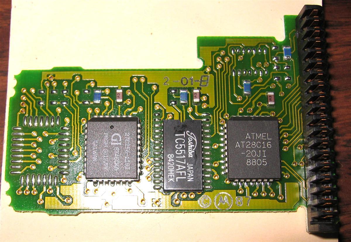
The MLM itself contains several large memory chips and additional components, including several zero-ohm resistors (jumpers) that select component size and type.
| Old | New |
|---|---|
 |
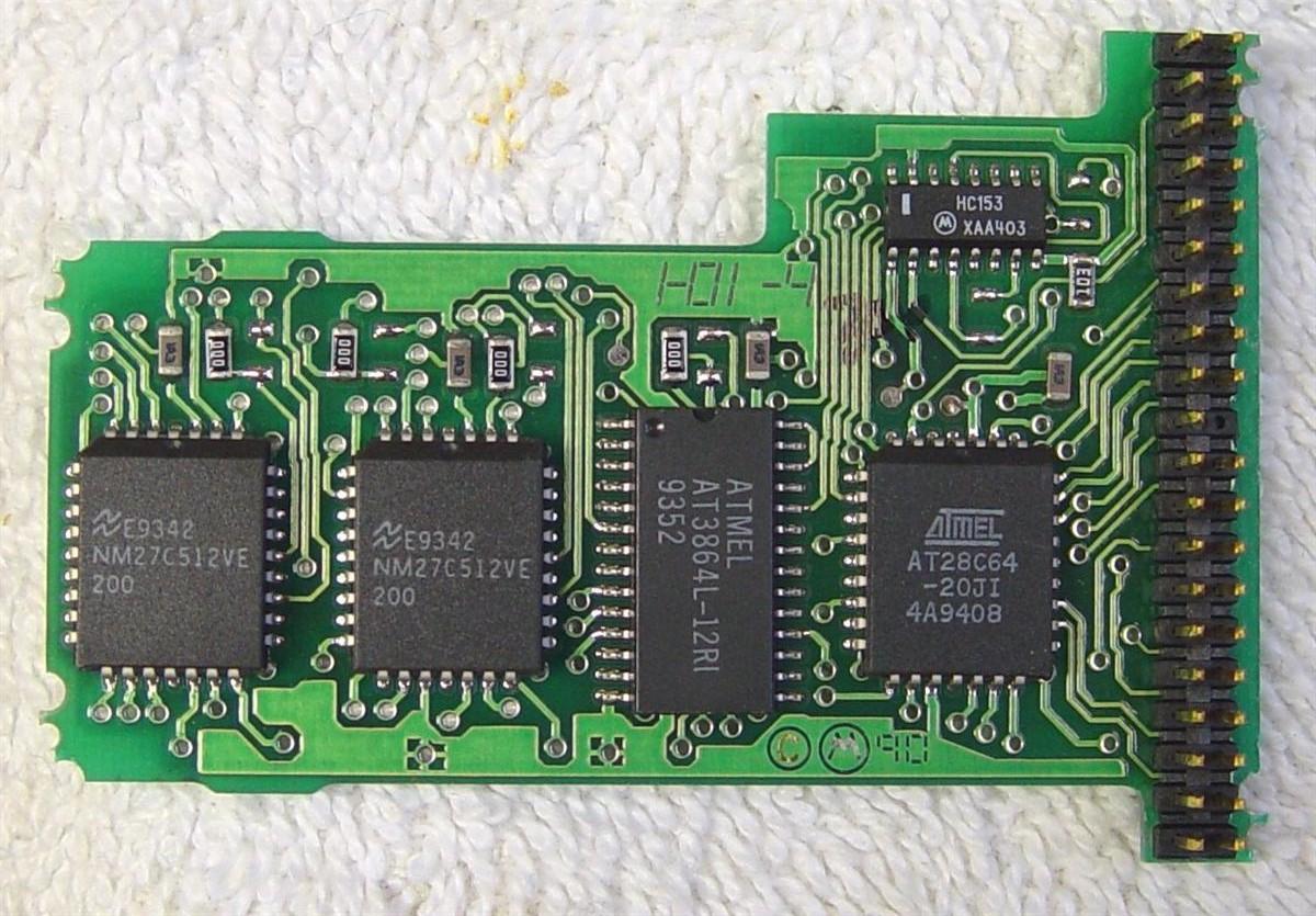 |
| One 27C512 program ROM | Two 27C512 program ROMs |
| Epson? SRM2016M static RAM | Atmel 3864L static RAM |
| Atmel 28C16 EEPROM | Atmel 28C64 EEPROM |
| No selector IC | One 74HC153 selector IC |
Keith WE6R sent a photo of the command board with a HearClear board and MLM from a 900 MHz radio. Note the firmware version: 1.00. This radio has a March 1989 date on its birth certificate inside the cover.

Acknowledgements and Credits:
The old boards were graciously provided by Travis Taylor of Florida, who also is adept at time-bomb capacitor replacement.
Keith WE6R supplied internal photos of an old 900 MHz radio.
Tim KF7EUO supplied a photo of a 900 MHz RF Board and VCO.
Contact Information:
The author can be contacted at: his-callsign [ at ] comcast [ dot ] net.
Back to the top of the page
Up one level (Spectra index)
Up two levels (Moto index)
Back to Home
This page originally posted 27-Oct-09.
Article text, most photographs, and hand-coded HTML
© Copyright 2009 By Robert W. Meister WA1MIK.
This web page, this web site, the information presented in and on its pages and in these modifications and conversions is © Copyrighted 1995 and (date of last update) by Kevin Custer W3KKC and multiple originating authors. All Rights Reserved, including that of paper and web publication elsewhere.