Up two levels (Moto index)
Back to Home
Spectra / Astro-Spectra
Programming Cable
By Robert W. Meister WA1MIK
|
Up one level (Spectra index) Up two levels (Moto index) Back to Home |
Making Your Own Spectra / Astro-Spectra Programming Cable By Robert W. Meister WA1MIK |
|
Background:
The Spectra mobile radios come in front (under dash) mount, and trunk (remote) mount. There are low-power, medium-power, and high-power versions, although the high-power radios are remote-mount only. None of these radios have an internal loudspeaker, all use an external speaker that is cabled to the accessory jack (in the case of front mount) or to a connector on the control head cable (in the case of remote mount).
The low- and medium-power dash-mount radios have a DA-15F accessory jack on the rear of the chassis with a special retaining clip that only properly fits over a very thin connector hood. Programming is accomplished through this connector. High-power and some remote-mount radios have a separate DB-25 (female) jack on the radio chassis next to the control cable jack and this connector is used for accessories and for programming. This article does not directly address the high-power radios since the author does not own one, however you could easily add another DB-25 male connector to the cable and then have one cable for all your Spectra programming.
Below is the rear view of a medium power 900 MHz Spectra dash-mount radio.
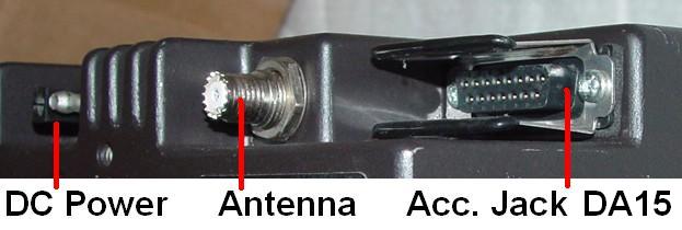
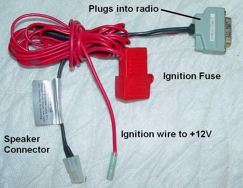
The official Ignition Control Cable, p/n 3080091M01, normally plugs into this jack. Spectras will not operate without +12V applied to the ignition control (sometimes called Ignition Sense) pin on this connector, which also provides the only connection for the loudspeaker (Spectras do not have an internal speaker). Astro-Spectras have a jumper option inside the control head that eliminates the requirement for an Ignision Sense wire in the accessory connector. This is what the cable looks like:
Low/Medium-Power Accessory Jack:
The following table shows the DA-15F pins and their function.
| Spectra Low/Medium-Power Accessory Jack (DA-15F) Signals |
||
|---|---|---|
| Pin # | Function | Notes |
| 1 | Jumper Settable | Note 1 |
| 2 | Emergency Switch | Note 2 |
| 3 | VIP Output #2 | Dash-mount only |
| 4 | SWB+ | Note 3 |
| 5 | Ignition Control | Note 4 |
| 6 | Speaker Output Hi | Do Not Ground! Note 5 |
| 7 | Speaker Output Lo | Do Not Ground! Note 5 |
| 8 | Digital Ground | |
| 9 | Busy | Programming |
| 10 | Bus- | Programming |
| 11 | Jumper Settable | Note 1 |
| 12 | VIP Output #1 | Dash-mount only |
| 13 | Jumper Settable | Note 1 |
| 14 | Bus+ | Programming |
| 15 | Jumper Settable | Note 1 |
Notes:
[1]: Pins 1, 11, 13 and 15 each have several surface-mount zero-ohm jumpers on the
command board that determine which signal appears on the pin, and some signals are also
dependent on options programmed with the RSS. Refer to the manual for the possibilities
and jumper configurations.
[2]: The normal accessory cable connects the Emergency Switch input (2) to ground
(8). Opening (ungrounding) this line will turn on the radio and cause it to transmit a
panic message, if the radio was programmed to do that. The Emergency Switch input can be
configured for active high or active low by a jumper (JU502) on the command board. The
default is the jumper installed (active high) and the Emergency Switch input pin connected
to ground (i.e. a normally closed switch that grounds pin 2 and opens when activated).
[3]: Switched +12v power from the radio to an accessory or to the RIB.
[4]: The Ignition Control input (5) is fed through a fuse to a source of +12 volts
that is present when the ignition switch is turned on. It can also be tied directly to a
constant +12V supply. This input line draws about 1mA DC whether the radio is on or off.
[5]: Both sides of the loudspeaker are driven by the audio amplifier. Grounding either
line will destroy the audio final amplifier IC on the command board. If you need to connect
something, such as test equipment, to the speaker wires, use an 8-ohm to 8-ohm isolation
transformer, such as the Motorola p/n SLN6435A. High end car stereo shops also have similar
transformers (and a 3 to 5 watt transformer is plenty for the test bench).
The programming signals are BUS+ (14), BUS- (10), BUSY (9), and digital ground (8). The cable also passes the SWB+ signal (4) to power the Radio Interface Box (RIB). Not all RIBs will accept power from the radio. My non-Motorola RIB needed its own battery power to work properly, while another one was happy without an internal battery.
The so-called RIB-less cables, that work with MaxTrac, Radius, or GTX radios, do not have all the necessary signals to program a Spectra. However, someone has just come out with a RIB-less cable specifically for the low/medium-power Spectra and Astro Spectra radios. (I was informed about this at the end of March 2010 via reader e-mail.) It has the necessary electronics inside the hoods of the connectors. There's a DA-15 at one end that plugs into the radio's accessory jack, and a DE-9 at the other end that plugs into a computer. An ignition control wire dangles out of the DA-15. It costs about $50US (March 2010). This is about what it costs to buy a RIB and make your own programming cable, but you can use the RIB on all Motorola radios with the right cable. A RIB-less cable can only be used on the radio series for which it was made. For my money, and due to the various radios I program, a RIB and three cables was a much better investment for me.
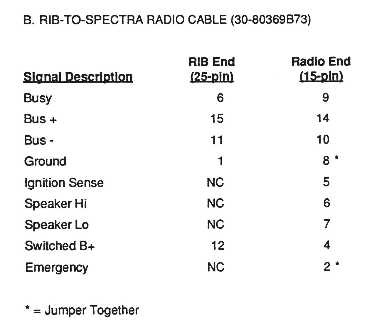
The official Motorola Radio-To-RIB, low/medium-power cable (DA-15), is p/n 3080369B73; the high-power cable (DB-25) is p/n 0180300B10. The wiring for the low/medium-power cable is shown below; diagrams for programming cables and the RIB itself can be found elsewhere on the web.
The Existing Configuration:
Since I have a medium-power Spectra mobile, there's already an accessory cable plugged into the jack at the back of the radio. If I want to program the radio, I need to unplug the accessory cable and plug in a programming cable. I need to supply +12V ignition voltage to allow the radio to turn on. The programming cable must also short the emergency switch input to ground. If I want to hear signals while the programming cable is plugged in, I'd need to add wires and the proper connector to deal with the loudspeaker. I'd also have to unplug the speaker from the existing accessory cable and plug it into the programming cable. This is a lot of work. There has to be a better way.
Some people use a programming cable with the ignition control line wired to a cigarette lighter plug. They omit the speaker wiring and deal with the emergency switch input. On the bench, they provide +12V to a cigarette lighter socket and plug the programming cable's ignition control wire into that.
How My Cable Fits In:
I decided to make my cable go in series with the existing accessory cable and the radio's accessory jack. I pass through the important signals: ignition control, emergency switch, loudspeaker hi and lo, and digital ground. I run my own cable to a DB-25F connector, which plugs into the RIB. By using the same connector hoods as the original accessory cable, I'm assured of a proper fit in the retaining clip without deforming it; most of the other hoods are fatter. The radio will power up fine since it still sees +12V on the ignition control line. The existing mobile loudspeaker will work. Other accessories connected to the radio through the accessory jack will NOT function; this is no big deal for me but if your installation warrants it, you could utilize additional wires between the DA-15 connectors.
The primary benefit to using this cable is that the radio works just the way it did without the cable: you don't need to find a source of +12V for ignition control, or swap speaker cables.
NOTE: There are some radio configurations where the DA-15 ignition control cable plugs into a connector other than the rear DA-15 connector. These radios are still programmed via the rear DA-15 connector, but you do not want to unplug the ignition control cable to insert my programming cable. Plug the DA-15M from my cable into the rear DA-15 connector, ignore the DA-15F connector, and do NOT move the existing ignition control cable if the radio is already working properly.
Making The Cable:
I used 48 inches of Belden 8723 cable just becasue I had it. This cable consists of two individually shielded pairs of #22 wire with a common drain/ground wire. I cut off 8 inches to use between the DA-15 connectors, and the remaining 40 inch piece goes to the DB-25F which plugs into the RIB. You could probably use unshielded wire, but I had this handy. For noise immunity, I recommend using shielded cabling.
Strip about 3/4 inch of the outer jacket and foil. Separate the wires. Strip 1/8 inch from the end of each wire, twist the strands together, and tin the leads. Make the DA-15F end of the 8 inch cable first. Slide the hood over the wire and secure it now, because you won't be able to do it later, and you'll hate yourself in the morning if you forget. Then make the DB-25F end of the 40 inch cable, and slide its hood on as well. Feed the 8 inch cable through the remaining DA-15M hood and solder all of its wires - except the shield/drain - to the connector. Feed the 40 inch cable through the DA-15M hood and solder all of its wires - except the shield/drain - to the connector. Finally, twist the two shield/drain wires together and solder them to the DA-15M pin 8. Slide the hood down and secure it to the DA-15M. The wiring list, with the colors I used, is shown below.
| DB-25M for High Power Radio [1] |
DB-25F to RIB |
DA-15M to Low/Medium Power Acc Jack |
DA-15F to Acc Cable in vehicle |
||||
|---|---|---|---|---|---|---|---|
| Pin# | Color | Pin# | Color | Pin# | Signal Name | Pin# | Color |
| --- | ----- | --- | ----- | 2 | EMERG | 2 | Blk |
| 22 | Wht | 12 | Wht | 4 | SWB+ | --- | ----- |
| --- | ----- | --- | ----- | 5 | IGN CTRL | 5 | Red |
| --- | ----- | --- | ----- | 6 | SPKR HI | 6 | Wht |
| --- | ----- | --- | ----- | 7 | SPKR LO | 7 | Grn |
| 18 | Shld | 1 | Shld | 8 | DIG GND | 8 | Shld |
| 23 | Grn | 6 | Grn | 9 | BUSY | --- | ----- |
| 14 | Blk | 11 | Blk | 10 | BUS- | --- | ----- |
| 5 | Red | 15 | Red | 14 | BUS+ | --- | ----- |
Notes:
[1]: This is an optional cable and connector that is only used to program remote
mount or high power Spectra radios. You can wire just the DB25 connectors to make a
high-power-only programming cable. As I said above, I don't own a high-power Spectra, so
the information is here for documentation purposes only.
Colors are for the Belden 8723 I used, two pair shielded cable. Pairs are: Red/Blk, Wht/Grn.
As a sanity check, make sure the pins on the DA-15M connector only have one wire per pin EXCEPT PIN 8. The cable going to the RIB connects to four pins and the cable going to the DA-15F connects to four other pins except for DIG GND, which is common to both cables. Mis-wiring the cables may damage the radio, RIB, or both.
I bought the connectors and hoods from Mouser. The part numbers as of July 2012 are:
DB-25M connector: 156-1225T-E, hood: 152-6025
DB-25F connector: 156-1325T-E, hood: 152-6025
DA-15M connector: 156-1215T-E, hood: 152-6015
DA-15F connector: 156-1315T-E, hood: 152-6015
For completeness here are the Mouser part numbers for the speaker connector:
Speaker connector shell radio side - 1-4803180
Speaker female socket radio side - 571-606171
Speaker connector plug speaker side - 1-4803190
Speaker male pin speaker side - 571-606181
Each D-series connector costs about $1.00. Each hood costs about $2.50. You only need this low profile hood for the DA-15M that plugs into the radio; ordinary less-expensive hoods can be used elsewhere.
The low profile hoods specified above are exactly the same as the ones used by Motorola on their standard ignition control cable. They will fit precisely into the connector retaining clip on the back of the Spectra low- and medium-power radios, without requiring you to spread or remove the clip to fit thicker hoods.
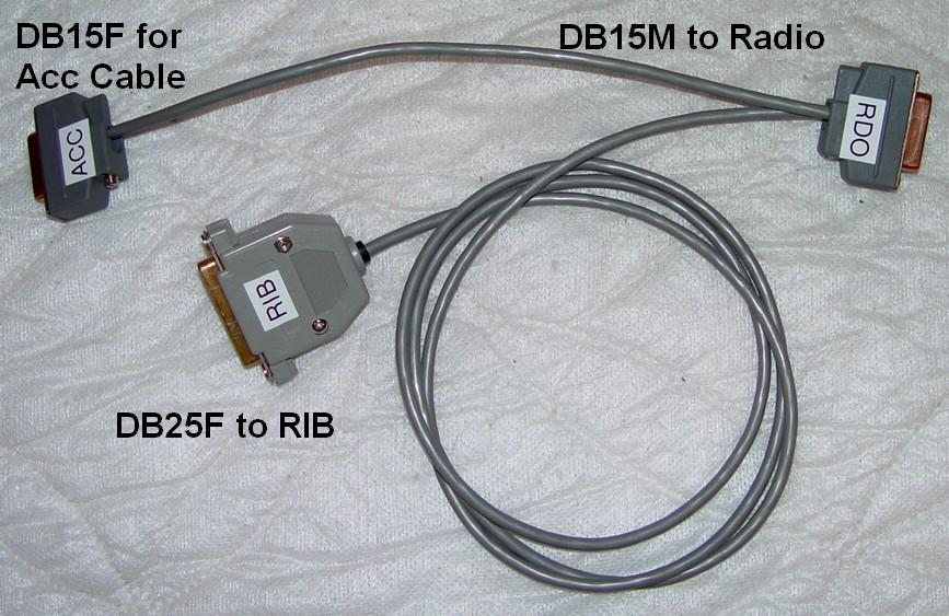
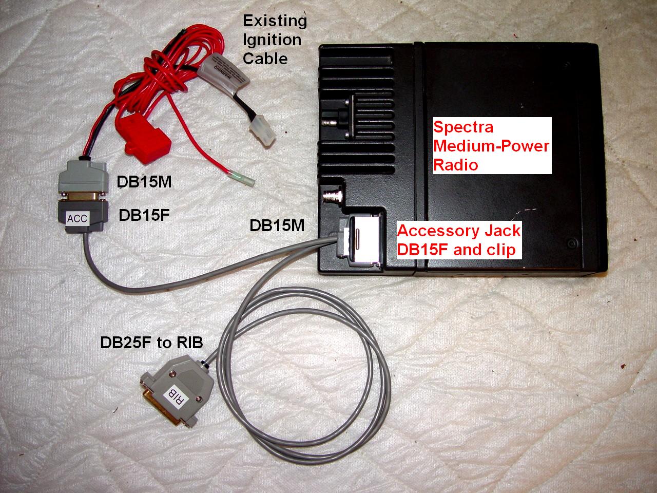
The finished cable is shown below. If you were to add the high power (DB-25) connector, the cable would be coming out of either the RIB connector or the RDO (radio) connector.
Putting It To Use:
Follow these simple steps to utilize this programming cable:
NOTE: If the radio has the emergency signaling feature enabled in the RSS, it may begin silently transmitting - WITH NO INDICATION ANYWHERE ON THE FRONT PANEL - as soon as you unplug any cable from the accessory jack. This can even occur when the radio is on the bench with no antenna connected. To prevent this from happening, unplug the main power cable before removing or installing anything plugged into the accessory jack. You can skip this step only if you know for a fact that the radio does NOT have emergency signaling enabled. Better safe than sorry. Once triggered, you can cancel an emergency transmit condition by pressing and releasing the microphone's PTT button, or by turning the radio off then on. It won't stop transmitting if you just turn the radio off - you must cycle the power completely. Of course, you can still pull the radio's main DC power cable to shut it down.
To remove the programming cable, follow these steps:
Here's a photo of the ignition cable, programming cable, and radio all hooked up to be used:
Remember: When you first acquire your Spectra make sure that you read and save the code plug (the old commercial frequencies) to a hard drive or floppy. Bad things have been known to happen during programming sessions, and you may have to revert to a previously archived known good code plug. It's better to have a backup code plug that you don't need, than to need a code plug you don't have.
A Final Note:
If you plug a programming cable into a Spectra radio, and the RIB is attached but not powered up, the radio will do all sorts of strange things - like turn on and off and display some error codes - when you turn it on. You'll think you have some bad connections. The RIB loads down the BUSY and BUS lines and this situation confuses the radio. The solution is to apply power to the RIB before turning the radio on. My RIB does not have a way of being powered from the radio; it can only run from its own internal 9V battery. The real Motorola RIB (RLN-4008 series) and some other clones can be powered by the radio if switched B+ is present on the DB-25F (radio programming cable) connector.
Acknowledgements and Credits:
Thanks go to Scott, KBØNLY, for telling me how his programming cable deals with Ignition Control, and for proofreading the article.
Thanks also go to Mike, K7IC, for letting me know about the oddball accessory cable configurations, the Emergency Switch jumper, and for proofreading the article. His site is one of two premiere sources of Spectra information.
Spectra, RSS, Radio Service Software, and a bunch more are registered trademarks of Motorola, Inc.
Connector information for the Spectra radios and the RIB was obtained from Motorola's official service manuals.
Contact:
The author can be contacted at: his-callsign [ at ] comcast [ dot ] net.
Back to the top of this page
Up one level (Spectra index)
Up two levels (Motorola index)
Back to Home
This article first posted January 2006.
This web page, this web site, the information presented in and on its pages and in these modifications and conversions is © Copyrighted 1995 and (date of last update) by Kevin Custer W3KKC and multiple originating authors. All Rights Reserved, including that of paper and web publication elsewhere.