Up two levels (Moto index)
Back to Home
By Robert W. Meister WA1MIK
|
Up one level (Spectra index) Up two levels (Moto index) Back to Home |
Adding a Preamp to a UHF Spectra Radio By Robert W. Meister WA1MIK |
|
Background:
Spectra mobile UHF radios are built from several modules. Some are frequency-specific, such as the receiver front end (RXFE), also called the pre-selector. This module has a ceramic band-pass filter and the mixer components. It also contains circuit traces (and possibly the components) for a built-in preamp. Unfortunately for us hams, finding the proper board with the preamp is nearly impossible, and now that regular Spectras are discontinued by the manufacturer, you can't even buy a new board. Most of the radios do not have the preamp. This article explains how you can add the components to your own board.
The UHF Spectra RXFEs came in four ranges, detailed below. The board part numbers are also provided.
| Board Range |
Frequency Range |
Band-pass Filter Center Frequency |
Non-Preamp Board |
With Preamp Board |
|---|---|---|---|---|
| 1 | 403-433 MHz | 417 MHz | HRE6001B | HRE6011B |
| 2 | 438-470 MHz | 455 MHz | HRE6002B | HRE6012B |
| 3 | 450-482 MHz | 465 MHz | HRE6003B | HRE6013B |
| 4 | 482-512 MHz | 497 MHz | HRE6004B | HRE6014B |
Note that a range 3 board with the preamp is not listed in the service manual. There was also a range 3.5 radio, which was the same as range 3 but had slightly higher frequency limits.
The Goal:
This procedure converts an HRE6003B range 3 non-preamp board into an HRE6013B range 3 preamp board. Refer to the schematic below to see the differences between the non-preamp board and the preamp board. Click on any image or photo for a larger view.

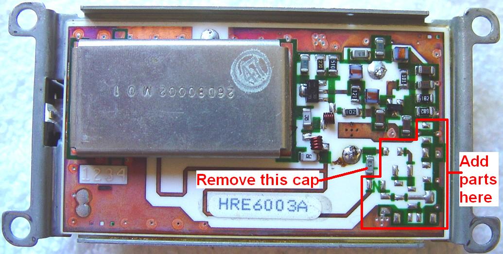
C125 couples the RF signal around the missing preamp components on the board. It must be removed when you install the preamp parts. Here's a photo of the original range 3 board without the preamp, with C125 identified. Note the letter "N" next to it, indicating no preamp:
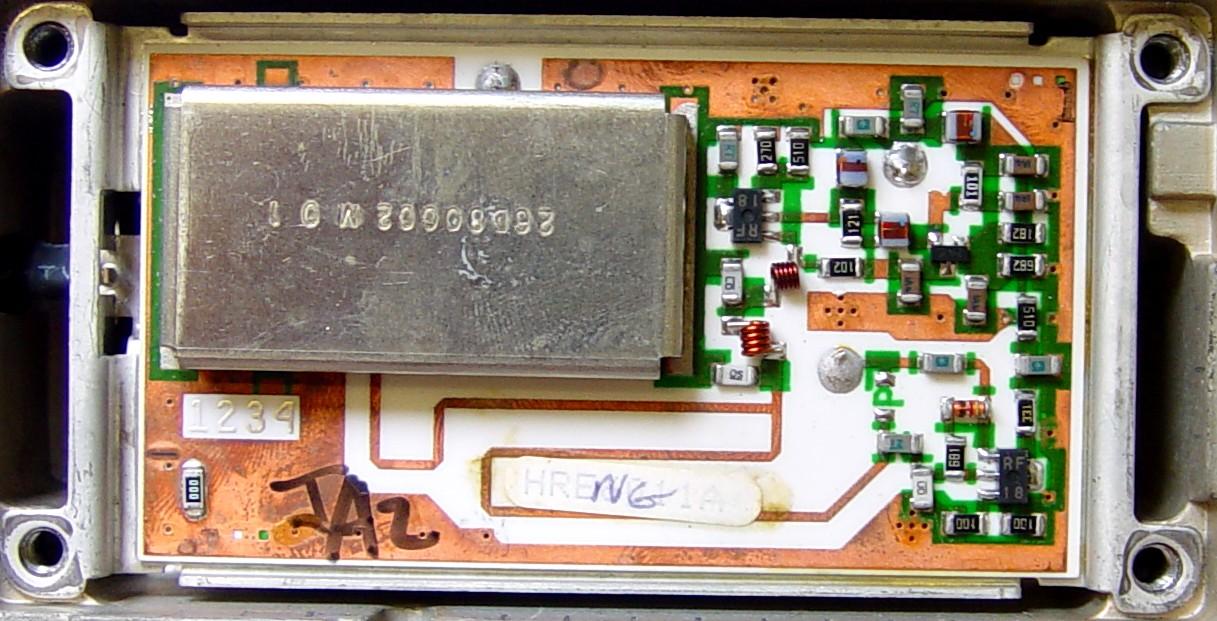
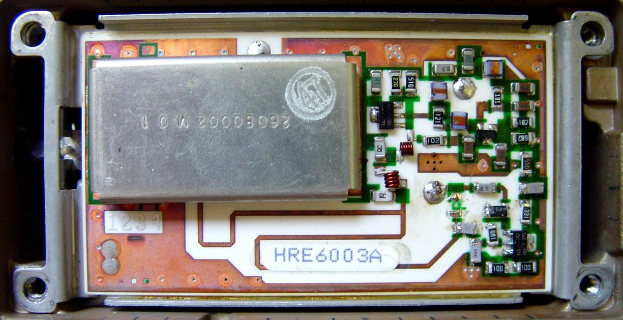
Here's a real HRE6011A board that has the preamp. Now that C125 has been removed, you can see the letter "P" in the spot where it was, indicating preamp.
Necessary Parts:
The following table shows the component values that are missing and need to be added. Refer to the various photos and images for more details.
| Name | Value | Motorola Part # | Price | Mouser Part # | Price |
|---|---|---|---|---|---|
| C100 | 1500 | 2113740B76 | 3.45 | 80-C1206C152J5G | 5.70 |
| C101 | 5.6 | 2113740B19 | 1.75 | 80-C1206C569J5G | 7.40 |
| C102 | 1500 | 2113740B76 | 3.45 | 80-C1206C152J5G | 5.70 |
| C103 | 91 | 2113740B48 [1] | --- | 80-C1206C101J5G | 1.00 |
| CR100 | 5.6V Zener | 4813830C15 [2] | 0.90 | 512-MMSZ5232B | 0.22 |
| Q100 | 2SC3357 | 4802000P02 | 1.40 | --- | --- |
| R100 | 10 | 0611077A26 | 0.34 | 263-10-RC | 0.80 |
| R101 | 10 | 0611077A26 | 0.34 | 263-10-RC | 0.80 |
| R102 | 680 | 0611077A70 [3] | --- | 263-680-RC | 0.80 |
| R103 | 330 | 0611077A62 [3] | --- | 263-330-RC | 0.80 |
| R104 | 51 | 0611077A43 | 0.55 | 263-51-RC | --- |
NOTES:
[1]: Obsolete Part; No Longer Available from Motorola; no replacement available. I
bought a 100pF capacitor from Mouser instead. After installing it, I realized that a
smaller size such as 0805 (where 91pF IS available) would have been a better fit.
[2]: The old part # 4882958R78, was replaced with new part # 4813830C15.
[3]: Obsolete Part; No Longer Available from Motorola; no replacement available.
These parts were purchased from Mouser instead.
Other Notes:
[4]: Capacitance values are in pF, 5%, 50V, size 1206. Motorola sells them as bags of
10 parts. Mouser sells them as individual parts. The price shown is for 10 parts.
[5]: Resistance values are in ohms, 5%, 1/8 watt, size 1206. Motorola sells them as
bags of 10 parts. Mouser sells them as individual parts. The price shown is for 10
parts.
[6]: The prices for CR100 and Q100 are for each individual part.
[7]: All prices shown were list price in US Dollars in June 2006.
The "size 1206" specifies the size, in hundredths of an inch, of the length and width of the component. So the parts on this assembly are 0.120 by 0.060 inches, nominally. The actual component could be several thousandths smaller. Some surface-mount parts have values or other identifying marks stenciled on one side.
Cautions and Orientation:
As with all sensitive electronics equipment, take the appropriate anti-static precautions when working on your radio. It is not necessary to completely remove the pre-selector board from the radio; you can work on it in place. The procedure below was done on a dash-mount radio, but it should be similar on a trunk-mount radio once the top cover has been removed.
The surface-mount components you'll be working with are extremely tiny but they seem to be quite resistant to high temperature soldering. A hot air soldering station is the preferred equipment to use. I used my old faithful 40w iron with a 1/16 inch tip and took great care. A magnifying glass would also be handy, and is strongly recommended. I'll be buying some of this equipment soon - these parts are TINY and the solder doesn't flow with the iron like I'm used to having it do with leaded components.
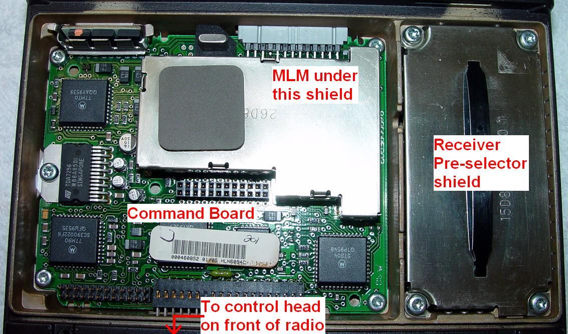
Here's a photo showing the major assemblies under the top cover of the radio:
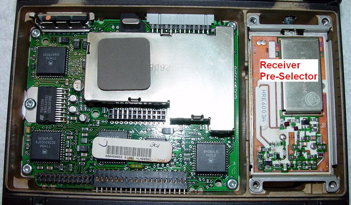
and here's the same view with the RXFE shield removed. These photos were taken after I added the preamp parts to the pre-selector:
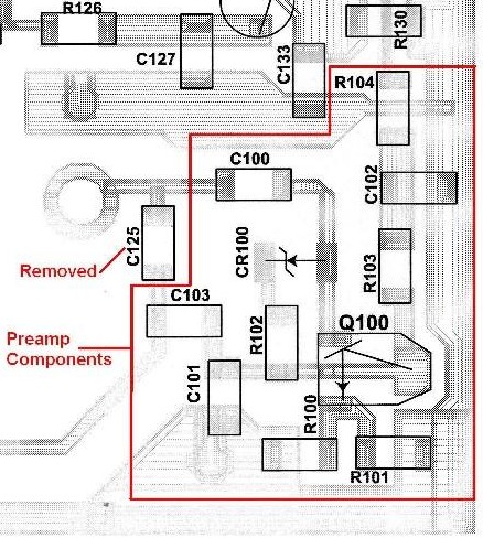
This image from the service manual shows where the parts are located:

Step-by-step Procedure:
If you print this photo while you're installing the parts, you can easily tell where they go.
The Results:
Here's a photo of the completed board with all the preamp components installed:
I used an Agilent E4430B RF signal generator as a signal source, and a Fluke 189 digital multi-meter to measure the audio across the loudspeaker terminals. The radio was fully unsquelched during these measurements.
The results of the sensitivity measurements (at 460.0 MHz) are shown below. Board #1 is the original board in my UHF Spectra. Board #2 is an identical board that was given to me by a friend as something I could experiment with, and was the subject for all of the photographs. Neither board had the preamp components when I started this project.
| Sensitivity Measurement |
Non-Preamp uV (dBm) |
With Preamp uV (dBm) |
Improvement in dB |
|---|---|---|---|
| 20dBQ Spec. 2002 | 0.500 (-113.0) | 0.300 (-117.5) | 4.5 |
| 20dBQ Spec. 1988 | 0.400 (-115.0) | 0.250 (-119.0) | 4.0 |
| Board #1 20dBQ | 0.349 (-116.0) | 0.224 (-120.0) | 4.0 |
| Board #1 25dBQ | 0.531 (-112.5) | 0.375 (-115.5) | 3.0 |
| Board #1 30dBQ | 0.945 (-107.5) | 0.668 (-110.5) | 3.0 |
| Board #1 35dBQ | 1.681 (-102.5) | 1.187 (-105.5) | 3.0 |
| Board #2 20dBQ | 0.502 (-113.0) | 0.266 (-118.5) | 5.5 |
| Board #2 25dBQ | 0.842 (-108.5) | 0.447 (-114.0) | 5.5 |
| Board #2 30dBQ | 1.498 (-103.5) | 0.795 (-109.0) | 5.5 |
| Board #2 35dBQ | 2.664 (- 98.5) | 1.414 (-104.0) | 5.5 |
The numbers tell the story. There's not much I can add. The procedure took me about an hour; I was very careful, double-checked the parts values, and took my time. The total amount of money to buy parts for 10 preamps is about $35; that makes the price per preamp quite inexpensive. I spent nearly $20 buying enough parts to add preamps to three RXFE boards, and I still have a few parts left over.
It is interesting to note that when I started, board #2 had 3-4dB poorer sensitivity than the original board #1 without the preamp, but it had 1-3dB better sensitivity than board #1 once the preamp was added. Board #1 didn't experience as much improvement as board #2, but it was better to begin with. It still makes the 20dB quieting specification.
Acknowledgements and Credits:
Thanks go to Dennis KD7YQM for starting me on this project and providing me with several pages of documentation and other valuable information.
Bob K2XD generously donated a spare HRE6003B board to me. He was fortunate enough to be able to buy a new HRE6012B board for his Spectra radio when they were still available.The schematic and component location diagrams were scanned from an Astro Digital Spectra Detailed Service Manual, 6881076C25-D. The RF sections are the same as a regular Spectra radio. This information is copyrighted by Motorola.
Contact Information:
The author can be contacted at: his-callsign [ at ] comcast [ dot ] net.
Back to the top of this page
Up one level (Spectra index)
Up two levels (Motorola index)
Back to Home
This web page, this web site, and the information presented in and on its pages is © Copyrighted 1995 and (date of last update) by Kevin Custer W3KKC and multiple originating authors.